You have 0 items in your cart

Chapter 10. Helicopter Operations
Section 1. Helicopter IFR Operations
-
Helicopter Flight Control Systems
- The certification requirements for helicopters to operate under Instrument Flight Rules (IFR) are contained in 14 CFR part 27, Airworthiness Standards: Normal Category Rotorcraft, and 14 CFR part 29, Airworthiness Standards: Transport Category Rotorcraft. To meet these requirements, helicopter manufacturers usually utilize a set of stabilization and/or Automatic Flight Control Systems (AFCSs).
-
Typically, these systems fall into the following categories:
- Aerodynamic surfaces, which impart some stability or control capability not found in the basic VFR configuration.
- Trim systems, which provide a cyclic centering effect. These systems typically involve a magnetic brake/spring device, and may also be controlled by a four-way switch on the cyclic. This is a system that supports “hands on” flying of the helicopter by the pilot.
- Stability Augmentation Systems (SASs), which provide short-term rate damping control inputs to increase helicopter stability. Like trim systems, SAS supports “hands on” flying.
- Attitude Retention Systems (ATTs), which return the helicopter to a selected attitude after a disturbance. Changes in desired attitude can be accomplished usually through a four-way “beep” switch, or by actuating a “force trim” switch on the cyclic, setting the attitude manually, and releasing. Attitude retention may be a SAS function, or may be the basic “hands off” autopilot function.
- Autopilot Systems (APs), which provide for “hands off” flight along specified lateral and vertical paths, including heading, altitude, vertical speed, navigation tracking, and approach. These systems typically have a control panel for mode selection, and system for indication of mode status. Autopilots may or may not be installed with an associated Flight Director System (FD). Autopilots typically control the helicopter about the roll and pitch axes (cyclic control) but may also include yaw axis (pedal control) and collective control servos.
- FDs, which provide visual guidance to the pilot to fly specific selected lateral and vertical modes of operation. The visual guidance is typically provided as either a “dual cue” (commonly known as a “cross-pointer”) or “single cue” (commonly known as a “vee-bar”) presentation superimposed over the attitude indicator. Some FDs also include a collective cue. The pilot manipulates the helicopter's controls to satisfy these commands, yielding the desired flight path, or may couple the flight director to the autopilot to perform automatic flight along the desired flight path. Typically, flight director mode control and indication is shared with the autopilot.
- In order to be certificated for IFR operation, a specific helicopter may require the use of one or more of these systems, in any combination.
- In many cases, helicopters are certificated for IFR operations with either one or two pilots. Certain equipment is required to be installed and functional for two pilot operations, and typically, additional equipment is required for single pilot operation. These requirements are usually described in the limitations section of the Rotorcraft Flight Manual (RFM).
- In addition, the RFM also typically defines systems and functions that are required to be in operation or engaged for IFR flight in either the single or two pilot configuration. Often, particularly in two pilot operation, this level of augmentation is less than the full capability of the installed systems. Likewise, single pilot operation may require a higher level of augmentation.
-
The RFM also identifies other specific limitations associated with IFR flight. Typically, these limitations include, but are not limited to:
- Minimum equipment required for IFR flight (in some cases, for both single pilot and two pilot operations).
-
Vmini (minimum speed - IFR).
NOTE-
The manufacturer may also recommend a minimum IFR airspeed during instrument approach.
- Vnei (never exceed speed - IFR).
- Maximum approach angle.
- Weight and center of gravity limits.
- Aircraft configuration limitations (such as aircraft door positions and external loads).
- Aircraft system limitations (generators, inverters, etc.).
- System testing requirements (many avionics and AFCS/AP/FD systems incorporate a self-test feature).
- Pilot action requirements (such as the pilot must have his/her hands and feet on the controls during certain operations, such as during instrument approach below certain altitudes).
- It is very important that pilots be familiar with the IFR requirements for their particular helicopter. Within the same make, model and series of helicopter, variations in the installed avionics may change the required equipment or the level of augmentation for a particular operation.
- During flight operations, pilots must be aware of the mode of operation of the augmentation systems, and the control logic and functions employed. For example, during an ILS approach using a particular system in the three-cue mode (lateral, vertical and collective cues), the flight director collective cue responds to glideslope deviation, while the horizontal bar of the “cross-pointer” responds to airspeed deviations. The same system, while flying an ILS in the two-cue mode, provides for the horizontal bar to respond to glideslope deviations. This concern is particularly significant when operating using two pilots. Pilots should have an established set of procedures and responsibilities for the control of flight director/autopilot modes for the various phases of flight. Not only does a full understanding of the system modes provide for a higher degree of accuracy in control of the helicopter, it is the basis for crew identification of a faulty system.
- Relief from the prohibition to takeoff with any inoperative instruments or equipment may be provided through a Minimum Equipment List (see 14 CFR section 91.213 and 14 CFR section 135.179, Inoperative Instruments and Equipment). In many cases, a helicopter configured for single pilot IFR may depart IFR with certain equipment inoperative, provided a crew of two pilots is used. Pilots are cautioned to ensure the pilot-in-command and second-in-command meet the requirements of 14 CFR section 61.58, Pilot-in-Command Proficiency Check: Operation of Aircraft Requiring More Than One Pilot Flight Crewmember, and 14 CFR section 61.55, Second-in-Command Qualifications, or 14 CFR part 135, Operating Requirements: Commuter and On-Demand Operations, Subpart E, Flight Crewmember Requirements, and Subpart G, Crewmember Testing Requirements, as appropriate.
- Experience has shown that modern AFCS/AP/FD equipment installed in IFR helicopters can, in some cases, be very complex. This complexity requires the pilot(s) to obtain and maintain a high level of knowledge of system operation, limitations, failure indications and reversionary modes. In some cases, this may only be reliably accomplished through formal training.
-
Helicopter Instrument Approaches
- Instrument flight procedures (IFPs) permit helicopter operations to heliports and runways during periods of low ceilings and reduced visibility (e.g. approach/SID/STAR/en route). IFPs can be designed for both public and private heliports using FAA instrument criteria. The FAA does recognize there are non-FAA service providers with proprietary special criteria. Special IFPs are reviewed and approved by Flight Technologies and Procedures Division and may have specified aircraft performance or equipment requirements, special crew training, airport facility equipment, waivers from published standards, proprietary criteria and restricted access. Special IFPs are not published in the Federal Register or printed in government Flight Information Publications.
-
Helicopters are capable of flying any published IFPs, for which they are properly equipped, subject to the following limitations and conditions:
- Helicopters flying conventional (i.e. non-Copter) IAPs may reduce the visibility minima to not less than one-half the published Category A landing visibility minima, or 1/4 statute mile visibility/1200 RVR, whichever is greater, unless the procedure is annotated with “Visibility Reduction by Helicopters NA." This annotation means that there are penetrations of the final approach obstacle identification surface (OIS) and that the 14 CFR section 97.3 visibility reduction rule does not apply and you must take precaution to avoid any obstacles in the visual segment. No reduction in MDA/DA is permitted at any time. The helicopter may initiate the final approach segment at speeds up to the upper limit of the highest approach category authorized by the procedure, but must be slowed to no more than 90 KIAS at the missed approach point (MAP) in order to apply the visibility reduction. Pilots are cautioned that such a decelerating approach may make early identification of wind shear on the approach path difficult or impossible. If required, use the Inoperative Components and Visual Aids Table provided inside the front cover of the U.S. Terminal Procedures Publication to derive the Category A minima before applying the 14 CFR section 97.3 rule.
- Helicopters flying Copter IAPs should use the published minima, with no reductions allowed. Unless otherwise specified on the instrument procedure chart, 90 KIAS is the maximum speed on the approach.
-
Pilots flying Area Navigation (RNAV) Copter IAPs should also limit their speed to 90 KIAS unless otherwise specified on the instrument procedure chart. The final and missed approach segment speeds must be limited to no more than 70 KIAS unless otherwise charted. Military RNAV Copter IAPs are limited to no more than 90 KIAS throughout the procedure. Use the published minima; no reductions allowed.
NOTE-
Obstruction clearance surfaces are based on the aircraft speed identified on the approach chart and have been designed on RNAV approaches for 70 knots unless otherwise indicated. If the helicopter is flown at higher speeds, it may fly outside of protected airspace. Some helicopters have a VMINI greater than 70 knots; therefore, they cannot meet the 70 knot limitation to conduct these RNAV approaches. Some helicopter autopilots, when used in the “go-around" mode, are programmed with a VYI greater than 70 knots. Therefore, those helicopters when using the autopilot “go-around" mode, cannot meet the 70 knot limitation for the RNAV approach. It may be possible to use the autopilot for the missed approach in other than the “go-around" mode and meet the 70 knot limitation. When operating at speeds other than VYI or VY, performance data may not be available in the RFM to predict compliance with climb gradient requirements. Pilots may use observed performance in similar weight/altitude/temperature/speed conditions to evaluate the suitability of performance. Pilots are cautioned to monitor climb performance to ensure compliance with procedure requirements.
NOTE-
VMINI - Instrument flight minimum speed, utilized in complying with minimum limit speed requirements for instrument flight
VYI - Instrument climb speed, utilized instead of VY for compliance with the climb requirements for instrument flight
VY - Speed for best rate of climb - TBL 10-1-1 summarizes these requirements.
- Even with weather conditions reported at or above minimums, under some combinations of reduced cockpit cutoff angle, approach/runway lighting, and high MDA/DH (coupled with a low visibility minima), the pilot may not be able to identify the required visual reference(s), or those references may only be visible in a very small portion of the available field of view. Even if identified by the pilot, the visual references may not support normal maneuvering and normal rates of descent to landing. The effect of such a combination may be exacerbated by other conditions such as rain on the windshield, or incomplete windshield defogging coverage.
-
Pilots should always be prepared to execute a missed approach even though weather conditions may be reported at or above minimums.
NOTE-
See paragraph 5-4-21, Missed Approach, for additional information on missed approach procedures.
TBL 10-1-1
Helicopter Use of Standard Instrument Approach ProceduresProcedure
Helicopter Visibility Minima
Helicopter MDA/DA
Maximum Speed Limitations
Conventional (non-Copter)
The greater of: one half the Category A visibility minima, 1/4 statute mile visibility, or 1200 RVR
As published for Category A
The helicopter may initiate the final approach segment at speeds up to the upper limit of the highest approach category authorized by the procedure, but must be slowed to no more than 90 KIAS at the MAP in order to apply the visibility reduction.
Copter Procedure
As published
As published
90 KIAS maximum when on a published route/track.
RNAV (GPS) Copter Procedure
As published
As published
The maximum speed for a Copter approach will be 90 KIAS or as published on the chart. Note: Higher approach angles may require a lower approach speed and aircraft VMINI. Military procedures are limited to 90 KIAS for all segments.
NOTE-
Several factors affect the ability of the pilot to acquire and maintain the visual references specified in 14 CFR section 91.175(c), even in cases where the flight visibility may be at the minimum derived from the criteria in TBL 10-1-1. These factors include, but are not limited to:
- Cockpit cutoff angle (the angle at which the cockpit or other airframe structure limits downward visibility below the horizon).
- Combinations of high MDA/DH and low visibility minimum, such as approaches with reduced helicopter visibility minima (per 14 CFR section 97.3).
- Type, configuration, and intensity of approach and runway/heliport lighting systems.
- Type of obscuring phenomenon and/or windshield contamination.
-
Helicopter Approach Procedures to VFR Heliports
-
The FAA may develop helicopter instrument approaches for heliports that do not meet the design standards for an IFR heliport. The majority of IFR approaches to VFR heliports are developed in support of Helicopter Air Ambulance (HAA) operators. These approaches may require use of conventional NAVAIDS or a RNAV system (e.g., GPS). They may be developed either as a special approach (pilot training is required for special procedures due to their unique characteristics) or a public approach (no special training required). These instrument procedures may be designed to guide the helicopter to a specific landing area (Proceed Visually) or to a point-in-space with a “Proceed VFR” segment.
-
An approach to a specific landing area. This type of approach is aligned to a missed approach point from which a landing can be accomplished with a maximum course change of 30 degrees. The visual segment from the MAP to the landing area is evaluated for obstacle hazards. These procedures are annotated: “PROCEED VISUALLY FROM (named MAP) OR CONDUCT THE SPECIFIED MISSED APPROACH.”
- “Proceed Visually” requires the pilot to acquire and maintain visual contact with the landing area at or prior to the MAP, or execute a missed approach. The visibility minimum is based on the distance from the MAP to the landing area, among other factors.
- The pilot is required to have the published minimum visibility throughout the visual segment flying the path described on the approach chart.
- Similar to an approach to a runway, the pilot is responsible for obstacle or terrain avoidance from the MAP to the landing area.
- Upon reaching the published MAP, or as soon as practicable thereafter, the pilot should advise ATC whether proceeding visually and canceling IFR or complying with the missed approach instructions. See paragraph 5-1-15, Canceling IFR Flight Plan.
-
Where any necessary visual reference requirements are specified by the FAA, at least one of the following visual references for the intended heliport is visible and identifiable before the pilot may proceed visually:
- FATO or FATO lights.
- TLOF or TLOF lights.
- Heliport Instrument Lighting System (HILS).
- Heliport Approach Lighting System (HALS).
- Visual Glideslope Indicator (VGSI).
- Windsock or windsock light.
- Heliport beacon.
- Other facilities or systems approved by the Flight Technologies and Procedures Division (AFS-400).
-
Approach to a Point-in-Space (PinS). At locations where the MAP is located more than 2 SM from the landing area, or the path from the MAP to the landing area is populated with obstructions which require avoidance actions or requires turn greater than 30 degrees, a PinS Proceed VFR procedure may be developed. These approaches are annotated “PROCEED VFR FROM (named MAP) OR CONDUCT THE SPECIFIED MISSED APPROACH.”
- These procedures require the pilot, at or prior to the MAP, to determine if the published minimum visibility, or the weather minimums required by the operating rule (e.g., part 91, part 135, etc.), or operations specifications (whichever is higher) is available to safely transition from IFR to VFR flight. If not, the pilot must execute a missed approach. For part 135 operations, pilots may not begin the instrument approach unless the latest weather report indicates that the weather conditions are at or above the authorized IFR minimums or the VFR weather minimums (as required by the class of airspace, operating rule and/or Operations Specifications) whichever is higher.
- Visual contact with the landing site is not required; however, the pilot must have the appropriate VFR weather minimums throughout the visual segment. The visibility is limited to no lower than that published in the procedure, until canceling IFR.
- IFR obstruction clearance areas are not applied to the VFR segment between the MAP and the landing site. Pilots are responsible for obstacle or terrain avoidance from the MAP to the landing area.
- Upon reaching the MAP defined on the approach procedure, or as soon as practicable thereafter, the pilot should advise ATC whether proceeding VFR and canceling IFR, or complying with the missed approach instructions. See paragraph 5-1-15, Canceling IFR Flight Plan.
- If the visual segment penetrates Class B, C, or D airspace, pilots are responsible for obtaining a Special VFR clearance, when required.
-
An approach to a specific landing area. This type of approach is aligned to a missed approach point from which a landing can be accomplished with a maximum course change of 30 degrees. The visual segment from the MAP to the landing area is evaluated for obstacle hazards. These procedures are annotated: “PROCEED VISUALLY FROM (named MAP) OR CONDUCT THE SPECIFIED MISSED APPROACH.”
-
The FAA may develop helicopter instrument approaches for heliports that do not meet the design standards for an IFR heliport. The majority of IFR approaches to VFR heliports are developed in support of Helicopter Air Ambulance (HAA) operators. These approaches may require use of conventional NAVAIDS or a RNAV system (e.g., GPS). They may be developed either as a special approach (pilot training is required for special procedures due to their unique characteristics) or a public approach (no special training required). These instrument procedures may be designed to guide the helicopter to a specific landing area (Proceed Visually) or to a point-in-space with a “Proceed VFR” segment.
-
The Gulf of America Grid System
-
On October 8, 1998, the Southwest Regional Office of the FAA, with assistance from the Helicopter Safety Advisory Conference (HSAC), implemented the world's first Instrument Flight Rules (IFR) Grid System in the Gulf of America. This navigational route structure is completely independent of ground-based navigation aids (NAVAIDs) and was designed to facilitate helicopter IFR operations to offshore destinations. The Grid System is defined by over 300 offshore waypoints located 20 minutes apart (latitude and longitude). Flight plan routes are routinely defined by just 4 segments: departure point (lat/long), first en route grid waypoint, last en route grid waypoint prior to approach procedure, and destination point (lat/long). There are over 4,000 possible offshore landing sites. Upon reaching the waypoint prior to the destination, the pilot may execute an Offshore Standard Approach Procedure (OSAP), a Helicopter En Route Descent Areas (HEDA) approach, or an Airborne Radar Approach (ARA). For more information on these helicopter instrument procedures, refer to FAA AC 90-80B, Approval of Offshore Standard Approach Procedures, Airborne Radar Approaches, and Helicopter En Route Descent Areas, on the FAA website http://www.faa.gov under Advisory Circulars. The return flight plan is just the reverse with the requested stand-alone GPS approach contained in the remarks section.
-
The large number (over 300) of waypoints in the grid system makes it difficult to assign phonetically pronounceable names to the waypoints that would be meaningful to pilots and controllers. A unique naming system was adopted that enables pilots and controllers to derive the fix position from the name. The five-letter names are derived as follows:
- The waypoints are divided into sets of 3 columns each. A three-letter identifier, identifying a geographical area or a NAVAID to the north, represents each set.
- Each column in a set is named after its position, i.e., left (L), center (C), and right (R).
-
The rows of the grid are named alphabetically from north to south, starting with A for the northern most row.
EXAMPLE-
LCHRC would be pronounced “Lake Charles Romeo Charlie.” The waypoint is in the right-hand column of the Lake Charles VOR set, in row C (third south from the northern most row).
- In December 2009, significant improvements to the Gulf of America grid system were realized with the introduction of ATC separation services using ADS-B. In cooperation with the oil and gas services industry, HSAC and Helicopter Association International (HAI), the FAA installed an infrastructure of ADS-B ground stations, weather stations (AWOS) and VHF remote communication outlets (RCO) throughout a large area of the Gulf of America. This infrastructure allows the FAA's Houston ARTCC to provide “domestic-like” air traffic control service in the offshore area beyond 12nm from the coastline to hundreds of miles offshore to aircraft equipped with ADS-B. Properly equipped aircraft can now be authorized to receive more direct routing, domestic en route separation minima and real time flight following. Operators who do not have authorization to receive ATC separation services using ADS-B, will continue to use the low altitude grid system and receive procedural separation from Houston ARTCC. Non-ADS-B equipped aircraft also benefit from improved VHF communication and expanded weather information coverage.
-
Three requirements must be met for operators to file IFR flight plans utilizing the grid:
- The helicopter must be equipped for IFR operations and equipped with IFR approved GPS navigational units.
- The operator must obtain prior written approval from the appropriate Flight Standards District Office through a Letter of Authorization or Operations Specification, as appropriate.
- The operator must be a signatory to the Houston ARTCC Letter of Agreement.
-
Operators who wish to benefit from ADS-B based ATC separation services must meet the following additional requirements:
- The Operator's installed ADS-B Out equipment must meet the performance requirements of one of the following FAA Technical Standard Orders (TSO), or later revisions: TSO-C154c, Universal Access Transceiver (UAT) Automatic Dependent Surveillance-Broadcast (ADS-B) Equipment, or TSO-C166b, Extended Squitter Automatic Dependent Surveillance-Broadcast (ADS-B) and Traffic Information.
-
Flight crews must comply with the procedures prescribed in the Houston ARTCC Letter of Agreement dated December 17, 2009, or later.
NOTE-
The unique ADS-B architecture in the Gulf of America depends upon reception of an aircraft's Mode C in addition to the other message elements described in 14 CFR 91.227. Flight crews must be made aware that loss of Mode C also means that ATC will not receive the aircraft's ADS-B signal.
- FAA/AIS publishes the grid system waypoints on the IFR Gulf of America Vertical Flight Reference Chart. A commercial equivalent is also available. The chart is updated annually and is available from an FAA approved print provider or FAA directly, website address: http://www.faa.gov/air_traffic/flight_info/aeronav.
-
The large number (over 300) of waypoints in the grid system makes it difficult to assign phonetically pronounceable names to the waypoints that would be meaningful to pilots and controllers. A unique naming system was adopted that enables pilots and controllers to derive the fix position from the name. The five-letter names are derived as follows:
-
On October 8, 1998, the Southwest Regional Office of the FAA, with assistance from the Helicopter Safety Advisory Conference (HSAC), implemented the world's first Instrument Flight Rules (IFR) Grid System in the Gulf of America. This navigational route structure is completely independent of ground-based navigation aids (NAVAIDs) and was designed to facilitate helicopter IFR operations to offshore destinations. The Grid System is defined by over 300 offshore waypoints located 20 minutes apart (latitude and longitude). Flight plan routes are routinely defined by just 4 segments: departure point (lat/long), first en route grid waypoint, last en route grid waypoint prior to approach procedure, and destination point (lat/long). There are over 4,000 possible offshore landing sites. Upon reaching the waypoint prior to the destination, the pilot may execute an Offshore Standard Approach Procedure (OSAP), a Helicopter En Route Descent Areas (HEDA) approach, or an Airborne Radar Approach (ARA). For more information on these helicopter instrument procedures, refer to FAA AC 90-80B, Approval of Offshore Standard Approach Procedures, Airborne Radar Approaches, and Helicopter En Route Descent Areas, on the FAA website http://www.faa.gov under Advisory Circulars. The return flight plan is just the reverse with the requested stand-alone GPS approach contained in the remarks section.
-
Departure Procedures
- When departing from a location on a point-in-space (PinS) SID with a visual segment indicated and the departure instruction describes the visual segment the aircraft must cross the initial departure fix (IDF) outbound at-or-above the altitude depicted on the chart. The helicopter will initially establish a hover at or above the heliport crossing height (HCH) specified on the chart. The HCH specifies a minimum hover height to begin the climb to assist in avoiding obstacles. The helicopter will leave the departure location on the published outbound heading/course specified, climbing at least 400 ft/per NM (or as depicted on the chart), remaining clear of clouds, crossing at or above the IDF altitude specified, prior to proceeding outbound on the procedure. For example the chart may include these instructions: “Hover at 15 ft AGL, then climb on track 005, remaining clear of clouds, to cross PAWLY at or above 700.”
- When flying a PinS SID procedure containing a segment with instructions to “proceed VFR,” the pilot must keep the aircraft clear of the clouds and cross the IDF outbound at or above the altitude depicted. Departure procedures that support multiple departure locations will have a Proceed VFR segment leading to the IDF. The chart will provide a bearing and distance to the IDF from the heliport. That bearing and distance are for pilot orientation purposes only and are not a required procedure track. The helicopter will leave the departure location via pilot navigation in order to align with the departure route and comply with the altitude specified at the IDF. For example, the chart may include these instructions: “VFR Climb to WEBBB, Cross WEBBB at or above 800.”
-
Once the aircraft reaches the IDF, the aircraft should proceed out the described route as specified on the chart, crossing each consecutive fix at or above the indicated altitude(s) until reaching the end of the departure or as directed by ATC.
FIG 10-1-1
Departure Charts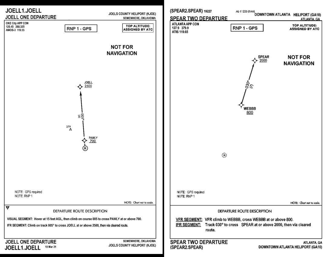
Section 2. Special Operations
-
Offshore Helicopter Operations
-
Introduction
The offshore environment offers unique applications and challenges for helicopter pilots. The mission demands, the nature of oil and gas exploration and production facilities, and the flight environment (weather, terrain, obstacles, traffic), demand special practices, techniques and procedures not found in other flight operations. Several industry organizations have risen to the task of reducing risks in offshore operations, including the Helicopter Safety Advisory Conference (HSAC) (http://www.hsac.org), and the Offshore Committee of the Helicopter Association International (HAI) (https://rotor.org/). The following recommended practices for offshore helicopter operations are based on guidance developed by HSAC for use in the Gulf of America, and provided here with their permission. While not regulatory, these recommended practices provide aviation and oil and gas industry operators with useful information in developing procedures to avoid certain hazards of offshore helicopter operations.NOTE-
Like all aviation practices, these recommended practices are under constant review. In addition to normal procedures for comments, suggested changes, or corrections to the AIM (contained in the Preface), any questions or feedback concerning these recommended procedures may also be directed to the HSAC through the feedback feature of the HSAC website (http://www.hsac.org).
-
Passenger Management on and about Heliport Facilities
- Background. Several incidents involving offshore helicopter passengers have highlighted the potential for incidents and accidents on and about the heliport area. The following practices will minimize risks to passengers and others involved in heliport operations.
-
Recommended Practices
- Heliport facilities should have a designated and posted passenger waiting area which is clear of the heliport, heliport access points, and stairways.
- Arriving passengers and cargo should be unloaded and cleared from the heliport and access route prior to loading departing passengers and cargo.
- Where a flight crew consists of more than one pilot, one crewmember should supervise the unloading/loading process from outside the aircraft.
- Where practical, a designated facility employee should assist with loading/unloading, etc.
-
Crane-Helicopter Operational Procedures
- Background. Historical experience has shown that catastrophic consequences can occur when industry safe practices for crane/helicopter operations are not observed. The following recommended practices are designed to minimize risks during crane and helicopter operations.
-
Recommended Practices
-
Personnel awareness
- Crane operators and pilots should develop a mutual understanding and respect of the others' operational limitations and cooperate in the spirit of safety;
- Pilots need to be aware that crane operators sometimes cannot release the load to cradle the crane boom, such as when attached to wire line lubricators or supporting diving bells; and
- Crane operators need to be aware that helicopters require warm up before takeoff, a two-minute cool down before shutdown, and cannot circle for extended lengths of time because of fuel consumption.
- It is recommended that when helicopters are approaching, maneuvering, taking off, or running on the heliport, cranes be shutdown and the operator leave the cab. Cranes not in use must have their booms cradled, if feasible. If in use, the crane's boom(s) are to be pointed away from the heliport and the crane shutdown for helicopter operations.
- Pilots will not approach, land on, takeoff, or have rotor blades turning on heliports of structures not complying with the above practice.
-
It is recommended that cranes on offshore platforms, rigs, vessels, or any other facility, which could interfere with helicopter operations (including approach/departure paths):
- Be equipped with a red rotating beacon or red high intensity strobe light connected to the system powering the crane, indicating the crane is under power;
- Be designed to allow the operator a maximum view of the helideck area and should be equipped with wide-angle mirrors to eliminate blind spots; and
- Have their boom tips, headache balls, and hooks painted with high visibility international orange.
-
Personnel awareness
-
Helicopter/Tanker Operations
- Background. The interface of helicopters and tankers during shipboard helicopter operations is complex and may be hazardous unless appropriate procedures are coordinated among all parties. The following recommended practices are designed to minimize risks during helicopter/tanker operations:
-
Recommended Practices
- Management, flight operations personnel, and pilots should be familiar with and apply the operating safety standards set forth in “Guide to Helicopter/Ship Operations”, International Chamber of Shipping, Third Edition, 5-89 (as amended), establishing operational guidelines/standards and safe practices sufficient to safeguard helicopter/tanker operations.
- Appropriate plans, approvals, and communications must be accomplished prior to reaching the vessel, allowing tanker crews sufficient time to perform required safety preparations and position crew members to receive or dispatch a helicopter safely.
- Appropriate approvals and direct communications with the bridge of the tanker must be maintained throughout all helicopter/tanker operations.
- Helicopter/tanker operations, including landings/departures, must not be conducted until the helicopter pilot-in-command has received and acknowledged permission from the bridge of the tanker.
- Helicopter/tanker operations must not be conducted during product/cargo transfer.
- Generally, permission will not be granted to land on tankers during mooring operations or while maneuvering alongside another tanker.
-
Helideck/Heliport Operational Hazard Warning(s) Procedures
-
Background
- A number of operational hazards can develop on or near offshore helidecks or onshore heliports that can be minimized through procedures for proper notification or visual warning to pilots. Examples of hazards include but are not limited to:
- These and other operational hazards are currently minimized through timely dissemination of a written Notice to Airmen (NOTAM) for pilots by helicopter companies and operators. A NOTAM provides a written description of the hazard, time and duration of occurrence, and other pertinent information. ANY POTENTIAL HAZARD should be communicated to helicopter operators or company aviation departments as early as possible to allow the NOTAM to be activated.
- To supplement the existing NOTAM procedure and further assist in reducing these hazards, a standardized visual signal(s) on the helideck/heliport will provide a positive indication to an approaching helicopter of the status of the landing area. Recommended Practice(s) have been developed to reinforce the NOTAM procedures and standardize visual signals.
-
Background
-
Drilling Rig Perforating Operations: Helideck/Heliport Operational Hazard Warning(s)/Procedure(s)
- Background. A critical step in the oil well completion process is perforation, which involves the use of explosive charges in the drill pipe to open the pipe to oil or gas deposits. Explosive charges used in conjunction with perforation operations offshore can potentially be prematurely detonated by radio transmissions, including those from helicopters. The following practices are recommended.
-
Recommended Practices
-
Personnel Conducting Perforating Operations. Whenever perforating operations are scheduled and operators are concerned that radio transmissions from helicopters in the vicinity may jeopardize the operation, personnel conducting perforating operations should take the following precautionary measures:
- Notify company aviation departments, helicopter operators or bases, and nearby manned platforms of the pending perforation operation so the Notice to Airmen (NOTAM) system can be activated for the perforation operation and the temporary helideck closure.
- Close the deck and make the radio warning clearly visible to passing pilots, install a temporary marking (described in subparagraph 10-2-1i1(b)) with the words “NO RADIO” stenciled in red on the legs of the diagonals. The letters should be 24 inches high and 12 inches wide. (See FIG 10-2-1.)
- The marker should be installed during the time that charges may be affected by radio transmissions.
-
Pilots
- When operating within 1,000 feet of a known perforation operation or observing the white X with red “NO RADIO” warning indicating perforation operations are underway, pilots will avoid radio transmissions from or near the helideck (within 1,000 feet) and will not land on the deck if the X is present. In addition to communications radios, radio transmissions are also emitted by aircraft radar, transponders, ADS-B equipment, radar altimeters, and DME equipment, and ELTs.
- Whenever possible, make radio calls to the platform being approached or to the Flight Following Communications Center at least one mile out on approach. Ensure all communications are complete outside the 1,000 foot hazard distance. If no response is received, or if the platform is not radio equipped, further radio transmissions should not be made until visual contact with the deck indicates it is open for operation (no white “X”).
-
Personnel Conducting Perforating Operations. Whenever perforating operations are scheduled and operators are concerned that radio transmissions from helicopters in the vicinity may jeopardize the operation, personnel conducting perforating operations should take the following precautionary measures:
-
Hydrogen Sulfide Gas Helideck/Heliport Operational Hazard Warning(s)/Procedures
- Background. Hydrogen sulfide (H2S) gas: Hydrogen sulfide gas in higher concentrations (300-500 ppm) can cause loss of consciousness within a few seconds and presents a hazard to pilots on/near offshore helidecks. When operating in offshore areas that have been identified to have concentrations of hydrogen sulfide gas, the following practices are recommended.
-
Recommended Practices
-
Pilots
- Ensure approved protective air packs are available for emergency use by the crew on the helicopter.
- If shutdown on a helideck, request the supervisor in charge provide a briefing on location of protective equipment and safety procedures.
-
If while flying near a helideck and the visual red beacon alarm is observed or an unusually strong odor of “rotten eggs” is detected, immediately don the protective air pack, exit to an area upwind, and notify the suspected source field of the hazard.
FIG 10-2-1
Closed Helideck Marking - No Radio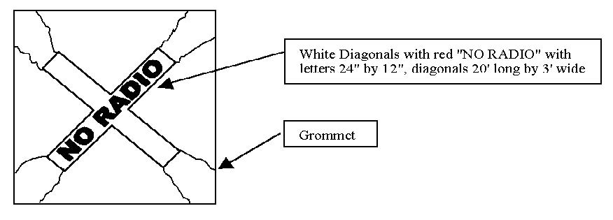
-
Oil Field Supervisors
- If presence of hydrogen sulfide is detected, a red rotating beacon or red high intensity strobe light adjacent to the primary helideck stairwell or wind indicator on the structure should be turned on to provide visual warning of hazard. If the beacon is to be located near the stairwell, the State of Louisiana “Offshore Heliport Design Guide” and FAA Advisory Circular (AC) 150/5390-2A, Heliport Design Guide, should be reviewed to ensure proper clearance on the helideck.
- Notify nearby helicopter operators and bases of the hazard and advise when hazard is cleared.
- Provide a safety briefing to include location of protective equipment to all arriving personnel.
- Wind socks or indicator should be clearly visible to provide upwind indication for the pilot.
-
Pilots
-
Gas Venting Helideck/Heliport Operational Hazard Warning(s)/Procedures - Operations Near Gas Vent Booms
- Background. Ignited flare booms can release a large volume of natural gas and create a hot fire and intense heat with little time for the pilot to react. Likewise, unignited gas vents can release reasonably large volumes of methane gas under certain conditions. Thus, operations conducted very near unignited gas vents require precautions to prevent inadvertent ingestion of combustible gases by the helicopter engine(s). The following practices are recommended.
-
Pilots
- Gas will drift upwards and downwind of the vent. Plan the approach and takeoff to observe and avoid the area downwind of the vent, remaining as far away as practicable from the open end of the vent boom.
- Do not attempt to start or land on an offshore helideck when the deck is downwind of a gas vent unless properly trained personnel verify conditions are safe.
-
Oil Field Supervisors
- During venting of large amounts of unignited raw gas, a red rotating beacon or red high intensity strobe light adjacent to the primary helideck stairwell or wind indicator should be turned on to provide visible warning of hazard. If the beacon is to be located near the stairwell, the State of Louisiana “Offshore Heliport Design Guide” and FAA AC 150/5390-2A, Heliport Design Guide, should be reviewed to ensure proper clearance from the helideck.
- Notify nearby helicopter operators and bases of the hazard for planned operations.
- Wind socks or indicator should be clearly visible to provide upward indication for the pilot.
-
Helideck/Heliport Operational Warning(s)/Procedure(s) - Closed Helidecks or Heliports
-
Background. A white “X” marked diagonally from corner to corner across a helideck or heliport touchdown area is the universally accepted visual indicator that the landing area is closed for safety of other reasons and that helicopter operations are not permitted. The following practices are recommended.
-
Permanent Closing. If a helideck or heliport is to be permanently closed, X diagonals of the same size and location as indicated above should be used, but the markings should be painted on the landing area.
NOTE-
White Decks: If a helideck is painted white, then international orange or yellow markings can be used for the temporary or permanent diagonals.
-
Temporary Closing. A temporary marker can be used for hazards of an interim nature. This marker could be made from vinyl or other durable material in the shape of a diagonal “X.” The marker should be white with legs at least 20 feet long and 3 feet in width. This marker is designed to be quickly secured and removed from the deck using grommets and rope ties. The duration, time, location, and nature of these temporary closings should be provided to and coordinated with company aviation departments, nearby helicopter bases, and helicopter operators supporting the area. These markers MUST be removed when the hazard no longer exists. (See FIG 10-2-2.)
FIG 10-2-2
Closed Helideck Marking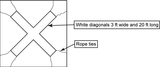
-
Permanent Closing. If a helideck or heliport is to be permanently closed, X diagonals of the same size and location as indicated above should be used, but the markings should be painted on the landing area.
-
Background. A white “X” marked diagonally from corner to corner across a helideck or heliport touchdown area is the universally accepted visual indicator that the landing area is closed for safety of other reasons and that helicopter operations are not permitted. The following practices are recommended.
-
Offshore (VFR) Operating Altitudes for Helicopters
- Background. Mid-air collisions constitute a significant percentage of total fatal offshore helicopter accidents. A method of reducing this risk is the use of coordinated VFR cruising altitudes. To enhance safety through standardized vertical separation of helicopters when flying in the offshore environment, it is recommended that helicopter operators flying in a particular area establish a cooperatively developed Standard Operating Procedure (SOP) for VFR operating altitudes. An example of such an SOP is contained in this example.
-
Recommended Practice Example
- Field Operations. Without compromising minimum safe operating altitudes, helicopters working within an offshore field “constituting a cluster” should use altitudes not to exceed 500 feet.
-
En Route Operations
- Helicopters operating below 750' AGL should avoid transitioning through offshore fields.
-
Helicopters en route to and from offshore locations, below 3,000 feet, weather permitting, should use en route altitudes as outlined in TBL 10-2-1.
TBL 10-2-1
Magnetic Heading
Altitude
0° to 179°
750'
1750'
2750'
180° to 359°
1250'
2250'
-
Area Agreements. See HSAC Area Agreement Maps for operating procedures for onshore high density traffic locations.
NOTE-
Pilots of helicopters operating VFR above 3,000 feet above the surface should refer to the current Federal Aviation Regulations (14 CFR part 91), and paragraph 3-1-4, Basic VFR Weather Minimums, of the AIM.
-
Landing Lights. Aircraft landing lights should be on to enhance aircraft identification:
- During takeoff and landings;
- In congested helicopter or fixed wing traffic areas;
- During reduced visibility; or,
- Anytime safety could be enhanced.
-
Offshore Helidecks/Landing Communications
- Background. To enhance safety, and provide appropriate time to prepare for helicopter operations, the following is recommended when anticipating a landing on an offshore helideck.
-
Recommended Practices
- Before landing on an offshore helideck, pilots are encouraged to establish communications with the company owning or operating the helideck if frequencies exist for that purpose.
-
When impracticable, or if frequencies do not exist, pilots or operations personnel should attempt to contact the company owning or operating the helideck by telephone. Contact should be made before the pilot departs home base/point of departure to advise of intentions and obtain landing permission if necessary.
NOTE-
It is recommended that communications be established a minimum of 10 minutes prior to planned arrival time. This practice may be a requirement of some offshore owner/operators.
NOTE-
-
Two (2) Helicopter Operations on Offshore Helidecks
- Background. Standardized procedures can enhance the safety of operating a second helicopter on an offshore helideck, enabling pilots to determine/maintain minimum operational parameters. Orientation of the parked helicopter on the helideck, wind and other factors may prohibit multi-helicopter operations. More conservative Rotor Diameter (RD) clearances may be required under differing condition, i.e., temperature, wet deck, wind (velocity/direction/gusts), obstacles, approach/departure angles, etc. Operations are at the pilot's discretion.
- Recommended Practice. Helideck size, structural weight capability, and type of main rotor on the parked and operating helicopter will aid in determining accessibility by a second helicopter. Pilots should determine that multi-helicopter deck operations are permitted by the helideck owner/operator.
-
Recommended Criteria
- Minimum one-third rotor diameter clearance (1/3 RD). The landing helicopter maintains a minimum 1/3 RD clearance between the tips of its turning rotor and the closest part of a parked and secured helicopter (rotors stopped and tied down).
- Three foot parking distance from deck edge (3'). Helicopters operating on an offshore helideck land or park the helicopter with a skid/wheel assembly no closer than 3 feet from helideck edge.
- Tiedowns. Main rotors on all helicopters that are shut down be properly secured (tied down) to prevent the rotor blades from turning.
- Medium (transport) and larger helicopters should not land on any offshore helideck where a light helicopter is parked unless the light helicopter is property secured to the helideck and has main rotor tied down.
- Helideck owners/operators should ensure that the helideck has a serviceable anti-skid surface.
-
Weight and limitations markings on helideck. The helideck weight limitations should be displayed by markings visible to the pilot (see State of Louisiana “Offshore Heliport Design Guide” and FAA AC 150/5390-2A, Heliport Design Guide).
NOTE-
Some offshore helideck owners/operators have restrictions on the number of helicopters allowed on a helideck. When helideck size permits, multiple (more than two) helicopter operations are permitted by some operators.
-
Helicopter Rapid Refueling Procedures (HRR)
-
Background. Helicopter Rapid Refueling (HRR), engine(s)/rotors operating, can be conducted safely when utilizing trained personnel and observing safe practices. This recommended practice provides minimum guidance for HRR as outlined in National Fire Protection Association (NFPA) and industry practices. For detailed guidance, please refer to National Fire Protection Association (NFPA) Document 407, “Standard for Aircraft Fuel Servicing,” 1990 edition, including 1993 HRR Amendment.
NOTE-
Certain operators prohibit HRR, or “hot refueling,” or may have specific procedures for certain aircraft or refueling locations. See the General Operations Manual and/or Operations Specifications to determine the applicable procedures or limitations.
-
Recommended Practices
- Only turbine-engine helicopters fueled with JET A or JET A-1 with fueling ports located below any engine exhausts may be fueled while an onboard engine(s) is (are) operating.
-
Helicopter fueling while an onboard engine(s) is (are) operating should only be conducted under the following conditions:
- A properly certificated and current pilot is at the controls and a trained refueler attending the fuel nozzle during the entire fuel servicing process. The pilot monitors the fuel quantity and signals the refueler when quantity is reached.
- No electrical storms (thunderstorms) are present within 10 nautical miles. Lightning can travel great distances beyond the actual thunderstorm.
- Passengers disembark the helicopter and move to a safe location prior to HRR operations. When the pilot-in-command deems it necessary for passenger safety that they remain onboard, passengers should be briefed on the evacuation route to follow to clear the area.
- Passengers not board or disembark during HRR operations nor should cargo be loaded or unloaded.
- Only designated personnel, trained in HRR operations should conduct HRR written authorization to include safe handling of the fuel and equipment. (See your Company Operations/Safety Manual for detailed instructions.)
- All doors, windows, and access points allowing entry to the interior of the helicopter that are adjacent to or in the immediate vicinity of the fuel inlet ports kept closed during HRR operations.
- Pilots ensure that appropriate electrical/electronic equipment is placed in standby-off position, to preclude the possibility of electrical discharge or other fire hazard, such as [i.e., weather radar is on standby and no radio transmissions are made (keying of the microphone/transmitter)]. Remember, in addition to communications radios, radio transmissions are also emitted by aircraft radar, transponders, ADS-B equipment, radar altimeters, DME equipment, and ELTs.
-
Smoking be prohibited in and around the helicopter during all HRR operations.
The HRR procedures are critical and present associated hazards requiring attention to detail regarding quality control, weather conditions, static electricity, bonding, and spill/fires potential.
Any activity associated with rotors turning (i.e.; refueling embarking/disembarking, loading/unloading baggage/freight; etc.) personnel should only approach the aircraft when authorized to do so. Approach should be made via safe approach path/walkway or “arc”- remain clear of all rotors.NOTE-
- Marine vessels, barges etc.: Vessel motion presents additional potential hazards to helicopter operations (blade flex, aircraft movement).
- See National Fire Protection Association (NFPA) Document 407, “Standard for Aircraft Fuel Servicing” for specifics regarding non-HRR (routine refueling operations).
-
Background. Helicopter Rapid Refueling (HRR), engine(s)/rotors operating, can be conducted safely when utilizing trained personnel and observing safe practices. This recommended practice provides minimum guidance for HRR as outlined in National Fire Protection Association (NFPA) and industry practices. For detailed guidance, please refer to National Fire Protection Association (NFPA) Document 407, “Standard for Aircraft Fuel Servicing,” 1990 edition, including 1993 HRR Amendment.
-
Introduction
-
Helicopter Night VFR Operations
-
Effect of Lighting on Seeing Conditions in Night VFR Helicopter Operations
NOTE-
This guidance was developed to support safe night VFR helicopter emergency medical services (HEMS) operations. The principles of lighting and seeing conditions are useful in any night VFR operation.
While ceiling and visibility significantly affect safety in night VFR operations, lighting conditions also have a profound effect on safety. Even in conditions in which visibility and ceiling are determined to be visual meteorological conditions, the ability to discern unlighted or low contrast objects and terrain at night may be compromised. The ability to discern these objects and terrain is the seeing condition, and is related to the amount of natural and man made lighting available, and the contrast, reflectivity, and texture of surface terrain and obstruction features. In order to conduct operations safely, seeing conditions must be accounted for in the planning and execution of night VFR operations. Night VFR seeing conditions can be described by identifying “high lighting conditions” and “low lighting conditions.”-
High lighting conditions exist when one of two sets of conditions are present:
- The sky cover is less than broken (less than 5/8 cloud cover), the time is between the local Moon rise and Moon set, and the lunar disk is at least 50% illuminated; or
-
The aircraft is operated over surface lighting which, at least, provides for the lighting of prominent obstacles, the identification of terrain features (shorelines, valleys, hills, mountains, slopes) and a horizontal reference by which the pilot may control the helicopter. For example, this surface lighting may be the result of:
- Extensive cultural lighting (man-made, such as a built-up area of a city),
- Significant reflected cultural lighting (such as the illumination caused by the reflection of a major metropolitan area's lighting reflecting off a cloud ceiling), or
- Limited cultural lighting combined with a high level of natural reflectivity of celestial illumination, such as that provided by a surface covered by snow or a desert surface.
- Low lighting conditions are those that do not meet the high lighting conditions requirements.
- Some areas may be considered a high lighting environment only in specific circumstances. For example, some surfaces, such as a forest with limited cultural lighting, normally have little reflectivity, requiring dependence on significant moonlight to achieve a high lighting condition. However, when that same forest is covered with snow, its reflectivity may support a high lighting condition based only on starlight. Similarly, a desolate area, with little cultural lighting, such as a desert, may have such inherent natural reflectivity that it may be considered a high lighting conditions area regardless of season, provided the cloud cover does not prevent starlight from being reflected from the surface. Other surfaces, such as areas of open water, may never have enough reflectivity or cultural lighting to ever be characterized as a high lighting area.
- Through the accumulation of night flying experience in a particular area, the operator will develop the ability to determine, prior to departure, which areas can be considered supporting high or low lighting conditions. Without that operational experience, low lighting considerations should be applied by operators for both pre-flight planning and operations until high lighting conditions are observed or determined to be regularly available.
-
High lighting conditions exist when one of two sets of conditions are present:
-
Astronomical Definitions and Background Information for Night Operations
-
Definitions
- Horizon. Wherever one is located on or near the Earth's surface, the Earth is perceived as essentially flat and, therefore, as a plane. If there are no visual obstructions, the apparent intersection of the sky with the Earth's (plane) surface is the horizon, which appears as a circle centered at the observer. For rise/set computations, the observer's eye is considered to be on the surface of the Earth, so that the horizon is geometrically exactly 90 degrees from the local vertical direction.
- Rise, Set. During the course of a day the Earth rotates once on its axis causing the phenomena of rising and setting. All celestial bodies, the Sun, Moon, stars and planets, seem to appear in the sky at the horizon to the East of any particular place, then to cross the sky and again disappear at the horizon to the West. Because the Sun and Moon appear as circular disks and not as points of light, a definition of rise or set must be very specific, because not all of either body is seen to rise or set at once.
- Sunrise and sunset refer to the times when the upper edge of the disk of the Sun is on the horizon, considered unobstructed relative to the location of interest. Atmospheric conditions are assumed to be average, and the location is in a level region on the Earth's surface.
- Moonrise and moonset times are computed for exactly the same circumstances as for sunrise and sunset. However, moonrise and moonset may occur at any time during a 24 hour period and, consequently, it is often possible for the Moon to be seen during daylight, and to have moonless nights. It is also possible that a moonrise or moonset does not occur relative to a specific place on a given date.
- Transit. The transit time of a celestial body refers to the instant that its center crosses an imaginary line in the sky - the observer's meridian - running from north to south.
- Twilight. Before sunrise and again after sunset there are intervals of time, known as “twilight,” during which there is natural light provided by the upper atmosphere, which does receive direct sunlight and reflects part of it toward the Earth's surface.
- Civil twilight is defined to begin in the morning, and to end in the evening when the center of the Sun is geometrically 6 degrees below the horizon. This is the limit at which twilight illumination is sufficient, under good weather conditions, for terrestrial objects to be clearly distinguished.
- Title 14 of the Code of Federal Regulations applies these concepts and definitions in addressing the definition of night (section 1.1), the requirement for aircraft lighting (section 91.209) and pilot recency of night experience (section 61.67).
-
Definitions
-
Information on Moon Phases and Changes in the Percentage of the Moon Illuminated
From any location on the Earth, the Moon appears to be a circular disk which, at any specific time, is illuminated to some degree by direct sunlight. During each lunar orbit (a lunar month), we see the Moon's appearance change from not visibly illuminated through partially illuminated to fully illuminated, then back through partially illuminated to not illuminated again. There are eight distinct, traditionally recognized stages, called phases. The phases designate both the degree to which the Moon is illuminated and the geometric appearance of the illuminated part. These phases of the Moon, in the sequence of their occurrence (starting from New Moon), are listed in FIG 10-2-3.FIG 10-2-3
Phases of the Moon
- The percent of the Moon's surface illuminated is a more refined, quantitative description of the Moon's appearance than is the phase. Considering the Moon as a circular disk, at New Moon the percent illuminated is 0; at First and Last Quarters it is 50%; and at Full Moon it is 100%. During the crescent phases the percent illuminated is between 0 and 50% and during gibbous phases it is between 50% and 100%.
- For practical purposes, phases of the Moon and the percent of the Moon illuminated are independent of the location on the Earth from where the Moon is observed. That is, all the phases occur at the same time regardless of the observer's position.
- For more detailed information, refer to the United States Naval Observatory site referenced below.
-
Access to Astronomical Data for Determination of Moon Rise, Moon Set, and Percentage of Lunar Disk Illuminated
- Astronomical data for the determination of Moon rise and set and Moon phase may be obtained from the United States Naval Observatory using an interactive query available at: http://aa.usno.navy.mil/
- Click on “Data Services,” and then on “Complete Sun and Moon Data for One Day.”
- You can obtain the times of sunrise, sunset, moonrise, moonset, transits of the Sun and Moon, and the beginning and end of civil twilight, along with information on the Moon's phase by specifying the date and location in one of the two forms on this web page and clicking on the “Get data” button at the end of the form. Form “A” is used for cities or towns in the U.S. or its territories. Form “B” for all other locations. An example of the data available from this site is shown in TBL 10-2-2.
-
Additionally, a yearly table may be constructed for a particular location by using the “Table of Sunrise/Sunset, Moonrise/Moonset, or Twilight Times for an Entire Year” selection.
TBL 10-2-2
Sample of Astronomical Data Available from the Naval ObservatoryThe following information is provided for New Orleans, Orleans Parish, Louisiana
(longitude W90.1, latitude N30.0)Tuesday
29 May 2007Central Daylight Time
SUN
Begin civil twilight
5:34 a.m.
Sunrise
6:01 a.m.
Sun transit
12:58 p.m.
Sunset
7:55 p.m.
End civil twilight
8:22 p.m.
MOON
Moonrise
5:10 p.m. on preceding day
Moonset
4:07 a.m.
Moonrise
6:06 p.m.
Moon transit
11:26 p.m.
Moonset
4:41 a.m. on following day
Phase of the Moon on 29 May: waxing gibbous with 95% of the Moon's visible disk illuminated.
Full Moon on 31 May 2007 at 8:04 p.m. Central Daylight Time.
-
Effect of Lighting on Seeing Conditions in Night VFR Helicopter Operations
-
Landing Zone Safety
- This information is provided for use by helicopter emergency medical services (HEMS) pilots, program managers, medical personnel, law enforcement, fire, and rescue personnel to further their understanding of the safety issues concerning Landing Zones (LZs). It is recommended that HEMS operators establish working relationships with the ground responder organizations they may come in contact with in their flight operations and share this information in order to establish a common frame of reference for LZ selection, operations, and safety.
- The information provided is largely based on the booklet, LZ - Preparing the Landing Zone, issued by National Emergency Medical Services Pilots Association (NEMSPA), and the guidance developed by the University of Tennessee Medical Center's LIFESTAR program, and is used with their permission. For additional information, go to http://www.nemspa.org/.
- Information concerning the estimation of wind velocity is based on the Beaufort Scale. See http://www.spc.noaa.gov/faq/tornado/beaufort.html for more information.
-
Selecting a Scene LZ
-
If the situation requires the use of a helicopter, first check to see if there is an area large enough to land a helicopter safely.
FIG 10-2-4
Recommended Minimum Landing Zone Dimensions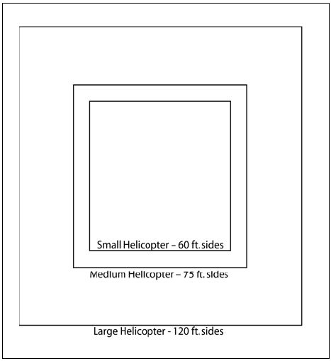
-
For the purposes of FIG 10-2-4 the following are provided as examples of relative helicopter size:
- Small Helicopter: Bell 206/407, Eurocopter AS-350/355, BO-105, BK-117.
- Medium Helicopter: Bell UH-1 (Huey) and derivatives (Bell 212/412), Bell 222/230/430 Sikorsky S-76, Eurocopter SA-365.
- Large Helicopter: Boeing Chinook, Eurocopter Puma, Sikorsky H-60 series (Blackhawk), SK-92.
- The LZ should be level, firm and free of loose debris that could possibly blow up into the rotor system.
-
The LZ should be clear of people, vehicles and obstructions such as trees, poles and wires. Remember that wires are difficult to see from the air. The LZ must also be free of stumps, brush, post and large rocks. See FIG 10-2-5.
FIG 10-2-5
Landing Zone Hazards
- Keep spectators back at least 200 feet. Keep emergency vehicles 100 feet away and have fire equipment (if available) standing by. Ground personnel should wear eye protection, if available, during landing and takeoff operations. To avoid loose objects being blown around in the LZ, hats should be removed; if helmets are worn, chin straps must be securely fastened.
- Fire fighters (if available) should wet down the LZ if it is extremely dusty.
-
If the situation requires the use of a helicopter, first check to see if there is an area large enough to land a helicopter safely.
-
Helping the Flightcrew Locate the Scene
- If the LZ coordinator has access to a GPS unit, the exact latitude and longitude of the LZ should be relayed to the HEMS pilot. If unable to contact the pilot directly, relay the information to the HEMS ground communications specialist for relaying to the pilot, so that they may locate your scene more efficiently. Recognize that the aircraft may approach from a direction different than the direct path from the takeoff point to the scene, as the pilot may have to detour around terrain, obstructions or weather en route.
- Especially in daylight hours, mountainous and densely populated areas can make sighting a scene from the air difficult. Often, the LZ coordinator on the ground will be asked if she or he can see or hear the helicopter.
-
Flightcrews use a clock reference method for directing one another's attention to a certain direction from the aircraft. The nose of the aircraft is always 12 o'clock, the right side is 3 o'clock, etc. When the LZ coordinator sees the aircraft, he/she should use this method to assist the flightcrew by indicating the scene's clock reference position from the nose of the aircraft. For example, “Accident scene is located at your 2 o'clock position.” See FIG 10-2-6.
FIG 10-2-6
“Clock” System for Identifying Positions Relative to the Nose of the Aircraft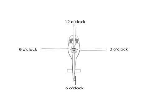
- When the helicopter approaches the scene, it will normally orbit at least one time as the flight crew observes the wind direction and obstacles that could interfere with the landing. This is often referred to as the “high reconnaissance” maneuver.
-
Wind Direction and Touchdown Area
- Determine from which direction the wind is blowing. Helicopters normally land and takeoff into the wind.
- If contact can be established with the pilot, either directly or indirectly through the HEMS ground communications specialist, describe the wind in terms of the direction the wind is from and the speed.
- Common natural sources of wind direction information are smoke, dust, vegetation movement, water streaks and waves. Flags, pennants, streamers can also be used. When describing the direction, use the compass direction from which the wind is blowing (example: from the North-West).
- Wind speed can be measured by small hand-held measurement devices, or an observer's estimate can be used to provide velocity information. The wind value should be reported in knots (nautical miles per hour). If unable to numerically measure wind speed, use TBL 10-2-3 to estimate velocity. Also, report if the wind conditions are gusty, or if the wind direction or velocity is variable or has changed recently.
-
If any obstacle(s) exist, ensure their description, position and approximate height are communicated to the pilot on the initial radio call.
TBL 10-2-3
Table of Common References for Estimating Wind VelocityWind (Knots)
Wind Classification
Appearance of Wind Effects
On the Water
On Land
Less than 1
Calm
Sea surface smooth and mirror-like
Calm, smoke rises vertically
1-3
Light Air
Scaly ripples, no foam crests
Smoke drift indicates wind direction, wind vanes are still
4-6
Light Breeze
Small wavelets, crests glassy, no breaking
Wind felt on face, leaves rustle, vanes begin to move
7-10
Gentle Breeze
Large wavelets, crests begin to break, scattered whitecaps
Leaves and small twigs constantly moving, light flags extended
11-16
Moderate Breeze
Small waves 1-4 ft. becoming longer, numerous whitecaps
Dust, leaves, and loose paper lifted, small tree branches move
17-21
Fresh Breeze
Moderate waves 4-8 ft. taking longer form, many whitecaps, some spray
Small trees in leaf begin to sway
22-27
Strong Breeze
Larger waves 8-13 ft., whitecaps common, more spray
Larger tree branches moving, whistling in wires
28-33
Near Gale
Sea heaps up, waves 13-20 ft., white foam streaks off breakers
Whole trees moving, resistance felt walking against wind
34-40
Gale
Moderately high (13-20 ft.) waves of greater length, edges of crests begin to break into spindrift, foam blown in streaks
Whole trees in motion, resistance felt walking against wind
41-47
Strong Gale
High waves (20 ft.), sea begins to roll, dense streaks of foam, spray may reduce visibility
Slight structural damage occurs, slate blows off roofs
48-55
Storm
Very high waves (20-30 ft.) with overhanging crests, sea white with densely blown foam, heavy rolling, lowered visibility
Seldom experienced on land, trees broken or uprooted, “considerable structural damage”
56-63
Violent Storm
Exceptionally high (30-45 ft.) waves, foam patches cover sea, visibility more reduced
64+
Hurricane
Air filled with foam, waves over 45 ft., sea completely white with driving spray, visibility greatly reduced
EXAMPLE-
Wind from the South-East, estimated speed 15 knots. Wind shifted from North-East about fifteen minutes ago, and is gusty.
-
Night LZs
-
There are several ways to light a night LZ:
-
Mark the touchdown area with five lights or road flares, one in each corner and one indicating the direction of the wind. See FIG 10-2-7.
FIG 10-2-7
Recommended Lighting for Landing Zone Operations at Night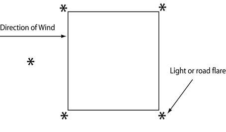
NOTE-
Road flares are an intense source of ignition and may be unsuitable or dangerous in certain conditions. In any case, they must be closely managed and firefighting equipment should be present when used. Other light sources are preferred, if available.
- If chemical light sticks may be used, care should be taken to assure they are adequately secured against being dislodged by the helicopter's rotor wash.
- Another method of marking a LZ uses four emergency vehicles with their low beam headlights aimed toward the intended landing area.
- A third method for marking a LZ uses two vehicles. Have the vehicles direct their headlight beams into the wind, crossing at the center of the LZ. (If fire/rescue personnel are available, the reflective stripes on their bunker gear will assist the pilot greatly.)
-
Mark the touchdown area with five lights or road flares, one in each corner and one indicating the direction of the wind. See FIG 10-2-7.
- At night, spotlights, flood lights and hand lights used to define the LZ are not to be pointed at the helicopter. However, they are helpful when pointed toward utility poles, trees or other hazards to the landing aircraft. White lights such as spotlights, flashbulbs and hi-beam headlights ruin the pilot's night vision and temporarily blind him. Red lights, however, are very helpful in finding accident locations and do not affect the pilot's night vision as significantly.
- As in Day LZ operations, ensure radio contact is accomplished between ground and air, if possible.
-
There are several ways to light a night LZ:
-
Ground Guide
- When the helicopter is in sight, one person should assist the LZ Coordinator by guiding the helicopter into a safe landing area. In selecting an LZ Coordinator, recognize that medical personnel usually are very busy with the patient at this time. It is recommended that the LZ Coordinator be someone other than a medical responder, if possible. Eye protection should be worn. The ground guide should stand with his/her back to the wind and his/her arms raised over his/her head (flashlights in each hand for night operations.)
- The pilot will confirm the LZ sighting by radio. If possible, once the pilot has identified the LZ, the ground guide should move out of the LZ.
- As the helicopter turns into the wind and begins a descent, the LZ coordinator should provide assistance by means of radio contact, or utilize the “unsafe signal” to wave off the helicopter if the LZ is not safe (see FIG 10-2-8). The LZ Coordinator should be far enough from the touchdown area that he/she can still maintain visual contact with the pilot.
-
Assisting the Crew
- After the helicopter has landed, do not approach the helicopter. The crew will approach you.
- Be prepared to assist the crew by providing security for the helicopter. If asked to provide security, allow no one but the crew to approach the aircraft.
- Once the patient is prepared and ready to load, allow the crew to open the doors to the helicopter and guide the loading of the patient.
- When approaching or departing the helicopter, always be aware of the tail rotor and always follow the directions of the crew. Working around a running helicopter can be potentially dangerous. The environment is very noisy and, with exhaust gases and rotor wash, often windy. In scene operations, the surface may be uneven, soft, or slippery which can lead to tripping. Be very careful of your footing in this environment.
-
The tail rotor poses a special threat to working around a running helicopter. The tail rotor turns many times faster than the main rotor, and is often invisible even at idle engine power. Avoid walking towards the tail of a helicopter beyond the end of the cabin, unless specifically directed by the crew.
NOTE-
Helicopters typically have doors on the sides of the cabin, but many use aft mounted “clamshell” type doors for loading and unloading patients on litters or stretchers. When using these doors, it is important to avoid moving any further aft than necessary to operate the doors and load/unload the patient. Again, always comply with the crew's instructions.
-
General Rules
- When working around helicopters, always approach and depart from the front, never from the rear. Approaching from the rear can increase your risk of being struck by the tail rotor, which, when at operating engine speed, is nearly invisible.
- To prevent injury or damage from the main rotor, never raise anything over your head.
- If the helicopter landed on a slope, approach and depart from the down slope side only.
- When the helicopter is loaded and ready for take off, keep the departure path free of vehicles and spectators. In an emergency, this area is needed to execute a landing.
-
Hazardous Chemicals and Gases
- Responding to accidents involving hazardous materials requires special handling by fire/rescue units on the ground. Equally important are the preparations and considerations for helicopter operations in these areas.
- Hazardous materials of concern are those which are toxic, poisonous, flammable, explosive, irritating, or radioactive in nature. Helicopter ambulance crews normally don't carry protective suits or breathing apparatuses to protect them from hazardous materials.
- The helicopter ambulance crew must be told of hazardous materials on the scene in order to avoid the contamination of the crew. Patients/victims contaminated by hazardous materials may require special precautions in packaging before loading on the aircraft for the medical crew's protection, or may be transported by other means.
- Hazardous chemicals and gases may be fatal to the unprotected person if inhaled or absorbed through the skin.
- Upon initial radio contact, the helicopter crew must be made aware of any hazardous gases in the area. Never assume that the crew has already been informed. If the aircraft were to fly through the hazardous gases, the crew could be poisoned and/or the engines could develop mechanical problems.
- Poisonous or irritating gases may cling to a victim's clothing and go unnoticed until the patient is loaded and the doors of the helicopter are closed. To avoid possible compromise of the crew, all of these patients must be decontaminated prior to loading.
-
Hand Signals
-
If unable to make radio contact with the HEMS pilot, use the following signals:
FIG 10-2-8
Recommended Landing Zone Ground Signals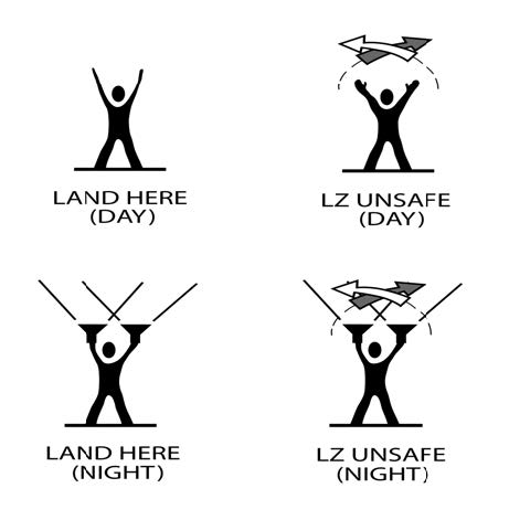
-
If unable to make radio contact with the HEMS pilot, use the following signals:
-
Emergency Situations
-
In the event of a helicopter accident in the vicinity of the LZ, consider the following:
-
Emergency Exits:
- Doors and emergency exits are typically prominently marked. If possible, operators should familiarize ground responders with the door system on their helicopter in preparation for an emergency event.
- In the event of an accident during the LZ operation, be cautious of hazards such as sharp and jagged metal, plastic windows, glass, any rotating components, such as the rotors, and fire sources, such as the fuel tank(s) and the engine.
-
Fire Suppression:
Helicopters used in HEMS operations are usually powered by turboshaft engines, which use jet fuel. Civil HEMS aircraft typically carry between 50 and 250 gallons of fuel, depending upon the size of the helicopter, and planned flight duration, and the fuel remaining after flying to the scene. Use water to control heat and use foam over fuel to keep vapors from ignition sources.
-
Emergency Exits:
-
In the event of a helicopter accident in the vicinity of the LZ, consider the following:
-
Emergency Medical Service (EMS) Multiple Helicopter Operations
- Background. EMS helicopter operators often overlap other EMS operator areas. Standardized procedures can enhance the safety of operating multiple helicopters to landing zones (LZs) and to hospital heliports. Communication is the key to successful operations and in maintaining organization between helicopters, ground units and communication centers. EMS helicopter operators which operate in the same areas should establish joint operating procedures and provide them to related agencies.
-
Recommended Procedures.
-
Landing Zone Operations. The first helicopter to arrive on-scene should establish communications with the ground unit at least 10 NMs from the LZ to receive a LZ briefing and to provide ground control the number of helicopters that can be expected. An attempt should be made to contact other helicopters on 123.025 to pass on to them pertinent LZ information and the ground unit's frequency. Subsequent helicopters arriving on scene should establish communications on 123.025 at least 10 NMs from the LZ. After establishing contact on 123.025, they should contact the ground unit for additional information. All helicopters should monitor 123.025 at all times.
- If the landing zone is not established by the ground unit when the first helicopter arrives, then the first helicopter should establish altitude and orbit location requirements for the other arriving helicopters. Recommended altitude separation between helicopters is 500 feet (weather and airspace permitting). Helicopters can orbit on cardinal headings from the scene coordinates. (See FIG 10-2-9.)
- Upon landing in the LZ, the first helicopter should update the other helicopters on the LZ conditions, i.e., space, hazards and terrain.
- Before initiating any helicopter movement to leave the LZ, all operators should attempt to contact other helicopters on 123.025, and state their position and route of flight intentions for departing the LZ.
-
Hospital Operations. Because many hospitals require landing permission and have established procedures (frequencies to monitor, primary and secondary routes for approaches and departures, and orbiting areas if the heliport is occupied) pilots should always receive a briefing from the appropriate facility (communication center, flight following, etc.) before proceeding to the hospital.
- In the event of multiple helicopters coming into the hospital heliport, the helicopter nearest to the heliport should contact other inbound helicopters on 123.025 and establish intentions. Follow the guidelines established in the LZ operations.
- To facilitate approach times, the pilot-in-command of the helicopter occupying the hospital heliport should advise any other operators whether the patient will be off loaded with the rotor blades turning or stopped, and the approximate time to do so.
-
Before making any helicopter movement to leave the hospital heliport, all operators should attempt to contact other helicopters on 123.025 and state their position and route of flight intentions for departing the heliport.
FIG 10-2-9
EMS Multiple Helicopter LZ/Heliport Operation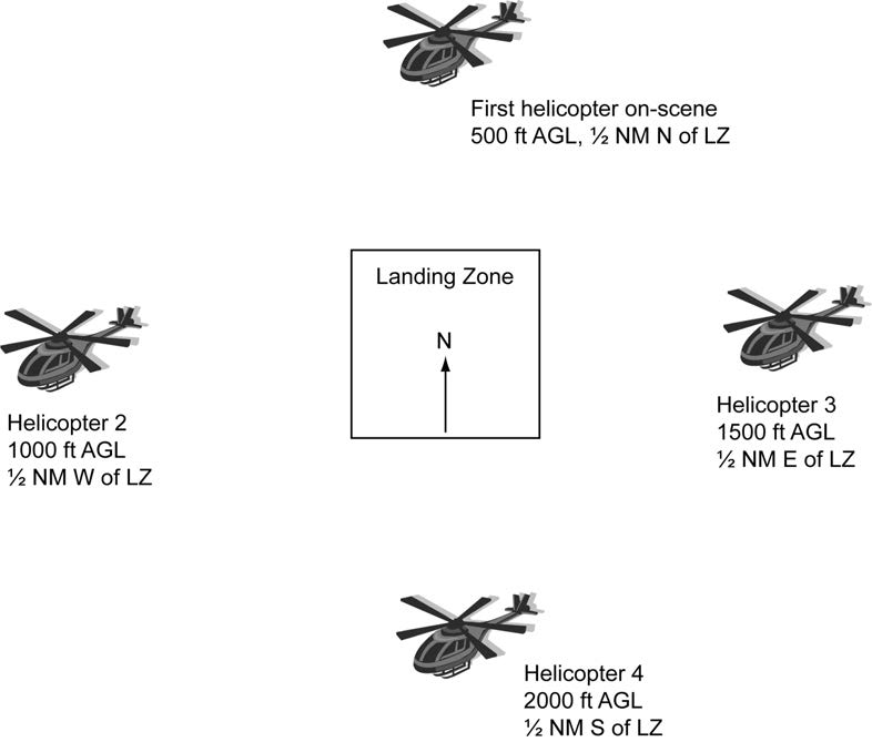
NOTE-
If the LZ/hospital heliport weather conditions or airspace altitude restrictions prohibit the recommended vertical separation, 1 NM separations should be kept between helicopter orbit areas.
-
Landing Zone Operations. The first helicopter to arrive on-scene should establish communications with the ground unit at least 10 NMs from the LZ to receive a LZ briefing and to provide ground control the number of helicopters that can be expected. An attempt should be made to contact other helicopters on 123.025 to pass on to them pertinent LZ information and the ground unit's frequency. Subsequent helicopters arriving on scene should establish communications on 123.025 at least 10 NMs from the LZ. After establishing contact on 123.025, they should contact the ground unit for additional information. All helicopters should monitor 123.025 at all times.