You have 0 items in your cart

Chapter 4. Air Traffic Control
- Section 1. Services Available to Pilots
- Section 2. Radio Communications Phraseology and Techniques
- Section 3. Airport Operations
- Section 4. ATC Clearances and Aircraft Separation
- Section 5. Surveillance Systems
- Section 6. Operational Policy/Procedures for Reduced Vertical Separation Minimum (RVSM) in the Domestic U.S., Alaska, Offshore Airspace and the San Juan FIR
- Section 7. Operational Policy/Procedures for the Gulf of America 50 NM Lateral Separation Initiative
Section 1. Services Available to Pilots
-
Air Route Traffic Control Centers
Centers are established primarily to provide air traffic service to aircraft operating on IFR flight plans within controlled airspace, and principally during the en route phase of flight.
-
Control Towers
Towers have been established to provide for a safe, orderly and expeditious flow of traffic on and in the vicinity of an airport. When the responsibility has been so delegated, towers also provide for the separation of IFR aircraft in the terminal areas.
REFERENCE-
AIM, Para 5-4-3, Approach Control.
-
Flight Service Stations
Flight Service Stations (FSSs) are air traffic facilities that provide pilot briefings, flight plan processing, en route flight advisories, search and rescue services, and assistance to lost aircraft and aircraft in emergency situations. FSSs also relay ATC clearances, process Notices to Airmen, and broadcast aviation weather and aeronautical information. In Alaska, designated FSSs also take weather observations, and provide Airport Advisory Services (AAS).
-
Recording and Monitoring
- Calls to air traffic control (ATC) facilities (ARTCCs, Towers, FSSs, Central Flow, and Operations Centers) over radio and ATC operational telephone lines (lines used for operational purposes such as controller instructions, briefings, opening and closing flight plans, issuance of IFR clearances and amendments, counter hijacking activities, etc.) may be monitored and recorded for operational uses such as accident investigations, accident prevention, search and rescue purposes, specialist training and evaluation, and technical evaluation and repair of control and communications systems.
- Where the public access telephone is recorded, a beeper tone is not required. In place of the “beep” tone the FCC has substituted a mandatory requirement that persons to be recorded be given notice they are to be recorded and give consent. Notice is given by this entry, consent to record is assumed by the individual placing a call to the operational facility.
-
Communications Release of IFR Aircraft Landing at an Airport Without an Operating Control Tower
Aircraft operating on an IFR flight plan, landing at an airport without an operating control tower will be advised to change to the airport advisory frequency when direct communications with ATC are no longer required. Towers and centers do not have nontower airport traffic and runway in use information. The instrument approach may not be aligned with the runway in use; therefore, if the information has not already been obtained, pilots should make an expeditious change to the airport advisory frequency when authorized.
REFERENCE-
AIM, Para 5-4-4, Advance Information on Instrument Approach.
-
Pilot Visits to Air Traffic Facilities
Pilots are encouraged to participate in local pilot/air traffic control outreach activities. However, due to security and workload concerns, requests for air traffic facility visits may not always be approved. Therefore, visit requests should be submitted through the air traffic facility as early as possible. Pilots should contact the facility and advise them of the number of persons in the group, the time and date of the proposed visit, and the primary interest of the group. The air traffic facility will provide further instructions if a request can be approved.
REFERENCE-
FAA Order 1600.69, FAA Facility Security Management Program.
-
Operation Rain Check
Operation Rain Check is a program designed and managed by local air traffic control facility management. Its purpose is to familiarize pilots and aspiring pilots with the ATC system, its functions, responsibilities and benefits.
REFERENCE-
FAA Order JO 7210.3, Para 4-2-2, Pilot Education.
FAA Order 1600.69, FAA Facility Security Management Program. -
Approach Control Service for VFR Arriving Aircraft
-
Numerous approach control facilities have established programs for arriving VFR aircraft to contact approach control for landing information. This information includes: wind, runway, and altimeter setting at the airport of intended landing. This information may be omitted if contained in the Automatic Terminal Information Service (ATIS) broadcast and the pilot states the appropriate ATIS code.
NOTE-
Pilot use of “have numbers” does not indicate receipt of the ATIS broadcast. In addition, the controller will provide traffic advisories on a workload permitting basis.
- Such information will be furnished upon initial contact with concerned approach control facility. The pilot will be requested to change to the tower frequency at a predetermined time or point, to receive further landing information.
- Where available, use of this procedure will not hinder the operation of VFR flights by requiring excessive spacing between aircraft or devious routing.
-
Compliance with this procedure is not mandatory but pilot participation is encouraged.
REFERENCE-
AIM, Para 4-1-18, Terminal Radar Services for VFR Aircraft.
NOTE-
Approach control services for VFR aircraft are normally dependent on ATC radar. These services are not available during periods of a radar outage.
-
Numerous approach control facilities have established programs for arriving VFR aircraft to contact approach control for landing information. This information includes: wind, runway, and altimeter setting at the airport of intended landing. This information may be omitted if contained in the Automatic Terminal Information Service (ATIS) broadcast and the pilot states the appropriate ATIS code.
-
Traffic Advisory Practices at Airports Without Operating Control Towers
(See TBL 4-1-1.)
-
Airport Operations Without Operating Control Tower
-
There is no substitute for alertness while in the vicinity of an airport. It is essential that pilots be alert and look for other traffic and exchange traffic information when approaching or departing an airport without an operating control tower. This is of particular importance since other aircraft may not have communication capability or, in some cases, pilots may not communicate their presence or intentions when operating into or out of such airports. To achieve the greatest degree of safety, it is essential that:
- All radio-equipped aircraft transmit/receive on a common frequency identified for the purpose of airport advisories; and
- Pilots use the correct airport name, as identified in appropriate aeronautical publications, to reduce the risk of confusion when communicating their position, intentions, and/or exchanging traffic information.
-
An airport may have a full or part‐time tower or FSS located on the airport, a full or part‐time UNICOM station or no aeronautical station at all. There are three ways for pilots to communicate their intention and obtain airport/traffic information when operating at an airport that does not have an operating tower: by communicating with an FSS, a UNICOM operator, or by making a self‐announce broadcast.
NOTE-
FSS airport advisories are available only in Alaska.
- Many airports are now providing completely automated weather, radio check capability and airport advisory information on an automated UNICOM system. These systems offer a variety of features, typically selectable by microphone clicks, on the UNICOM frequency. Availability of the automated UNICOM will be published in the Chart Supplement and approach charts.
-
There is no substitute for alertness while in the vicinity of an airport. It is essential that pilots be alert and look for other traffic and exchange traffic information when approaching or departing an airport without an operating control tower. This is of particular importance since other aircraft may not have communication capability or, in some cases, pilots may not communicate their presence or intentions when operating into or out of such airports. To achieve the greatest degree of safety, it is essential that:
-
Communicating on a Common Frequency
-
The key to communicating at an airport without an operating control tower is selection of the correct common frequency. The acronym CTAF which stands for Common Traffic Advisory Frequency, is synonymous with this program. A CTAF is a frequency designated for the purpose of carrying out airport advisory practices while operating to or from an airport without an operating control tower. The CTAF may be a UNICOM, MULTICOM, FSS, or tower frequency and is identified in appropriate aeronautical publications.
NOTE-
FSS frequencies are available only in Alaska.
TBL 4-1-1
Summary of Recommended Communication ProceduresCommunication/Broadcast Procedures
Facility at Airport
Frequency Use
Outbound
Inbound
Practice Instrument Approach
1.
UNICOM (No Tower or FSS)
Communicate with UNICOM station on published CTAF frequency (122.7; 122.8; 122.725; 122.975; or 123.0). If unable to contact UNICOM station, use self‐announce procedures on CTAF.
Before taxiing and before taxiing on the runway for departure.
10 miles out. Entering downwind, base, and final. Leaving the runway.
2.
No Tower, FSS, or UNICOM
Self‐announce on MULTICOM frequency 122.9.
Before taxiing and before taxiing on the runway for departure.
10 miles out. Entering downwind, base, and final. Leaving the runway.
Departing final approach fix (name) or on final approach segment inbound.
3.
No Tower in operation, FSS open (Alaska only)
Communicate with FSS on CTAF frequency.
Before taxiing and before taxiing on the runway for departure.
10 miles out. Entering downwind, base, and final. Leaving the runway.
Approach completed/terminated.
4.
FSS Closed (No Tower)
Self‐announce on CTAF.
Before taxiing and before taxiing on the runway for departure.
10 miles out. Entering downwind, base, and final. Leaving the runway.
5.
Tower or FSS not in operation
Self‐announce on CTAF.
Before taxiing and before taxiing on the runway for departure.
10 miles out. Entering downwind, base, and final. Leaving the runway.
6.
Designated CTAF Area (Alaska Only)
Self‐announce on CTAF designated on chart or Chart Supplement Alaska.
Before taxiing and before taxiing on the runway for departure until leaving designated area.
When entering designated CTAF area.
- CTAF (Alaska Only). In Alaska, a CTAF may also be designated for the purpose of carrying out advisory practices while operating in designated areas with a high volume of VFR traffic.
- The CTAF frequency for a particular airport or area is contained in the Chart Supplement U.S., Chart Supplement Alaska, Alaska Terminal Publication, Instrument Approach Procedure Charts, and Instrument Departure Procedure (DP) Charts. Also, the CTAF frequency can be obtained by contacting any FSS. Use of the appropriate CTAF, combined with a visual alertness and application of the following recommended good operating practices, will enhance safety of flight into and out of all uncontrolled airports.
-
The key to communicating at an airport without an operating control tower is selection of the correct common frequency. The acronym CTAF which stands for Common Traffic Advisory Frequency, is synonymous with this program. A CTAF is a frequency designated for the purpose of carrying out airport advisory practices while operating to or from an airport without an operating control tower. The CTAF may be a UNICOM, MULTICOM, FSS, or tower frequency and is identified in appropriate aeronautical publications.
-
Recommended Traffic Advisory Practices
- Pilots of inbound traffic should monitor and communicate as appropriate on the designated CTAF from 10 miles to landing. Pilots of departing aircraft should monitor/communicate on the appropriate frequency from start‐up, during taxi, and until 10 miles from the airport unless the CFRs or local procedures require otherwise.
- Pilots of aircraft conducting other than arriving or departing operations at altitudes normally used by arriving and departing aircraft should monitor/communicate on the appropriate frequency while within 10 miles of the airport unless required to do otherwise by the CFRs or local procedures. Such operations include parachute jumping/dropping, en route, practicing maneuvers, etc.
-
In Alaska, pilots of aircraft conducting other than arriving or departing operations in designated CTAF areas should monitor/communicate on the appropriate frequency while within the designated area, unless required to do otherwise by CFRs or local procedures. Such operations include parachute jumping/dropping, en route, practicing maneuvers, etc.
REFERENCE-
AIM, Para 3-5-4, Parachute Jump Aircraft Operations
-
Airport Advisory/Information Services Provided by a FSS
-
There are two advisory type services provided at selected airports.
- Local Airport Advisory (LAA) is available only in Alaska and provided at airports that have a FSS physically located on the airport, which does not have a control tower or where the tower is operated on a part-time basis. The CTAF for LAA airports is disseminated in the appropriate aeronautical publications.
- Remote Airport Information Service (RAIS) is provided in support of special events at nontowered airports by request from the airport authority.
-
In communicating with a CTAF FSS, check the airport's automated weather and establish two-way communications before transmitting outbound/inbound intentions or information. An inbound aircraft should initiate contact approximately 10 miles from the airport, reporting aircraft identification and type, altitude, location relative to the airport, intentions (landing or over flight), possession of the automated weather, and request airport advisory or airport information service. A departing aircraft should initiate contact before taxiing, reporting aircraft identification and type, VFR or IFR, location on the airport, intentions, direction of take-off, possession of the automated weather, and request airport advisory or information service. Also, report intentions before taxiing onto the active runway for departure. If you must change frequencies for other service after initial report to FSS, return to FSS frequency for traffic update.
-
Inbound
EXAMPLE-
Vero Beach radio, Centurion Six Niner Delta Delta is ten miles south, two thousand, landing Vero Beach. I have the automated weather, request airport advisory.
-
Outbound
EXAMPLE-
Vero Beach radio, Centurion Six Niner Delta Delta, ready to taxi to runway 22, VFR, departing to the southwest. I have the automated weather, request airport advisory.
-
Inbound
-
Airport advisory service includes wind direction and velocity, favored or designated runway, altimeter setting, known airborne and ground traffic, NOTAMs, airport taxi routes, airport traffic pattern information, and instrument approach procedures. These elements are varied so as to best serve the current traffic situation. Some airport managers have specified that under certain wind or other conditions designated runways be used. Pilots should advise the FSS of the runway they intend to use.
CAUTION-
All aircraft in the vicinity of an airport may not be in communication with the FSS.
-
There are two advisory type services provided at selected airports.
-
Information Provided by Aeronautical Advisory Stations (UNICOM)
- UNICOM is a nongovernment air/ground radio communication station which may provide airport information at public use airports where there is no tower or FSS.
- On pilot request, UNICOM stations may provide pilots with weather information, wind direction, the recommended runway, or other necessary information. If the UNICOM frequency is designated as the CTAF, it will be identified in appropriate aeronautical publications.
-
Unavailability of Information from FSS or UNICOM
Should LAA by an FSS or Aeronautical Advisory Station UNICOM be unavailable, wind and weather information may be obtainable from nearby controlled airports via Automatic Terminal Information Service (ATIS) or Automated Weather Observing System (AWOS) frequency. -
Self‐Announce Position and/or Intentions
- General.Self‐announce is a procedure whereby pilots broadcast their position or intended flight activity or ground operation on the designated CTAF. This procedure is used primarily at airports which do not have an FSS on the airport. The self‐announce procedure should also be used if a pilot is unable to communicate with the FSS on the designated CTAF. Pilots stating, “Traffic in the area, please advise” is not a recognized Self-Announce Position and/or Intention phrase and should not be used under any condition.
- If an airport has a tower and it is temporarily closed, or operated on a part‐time basis and there is no FSS on the airport or the FSS is closed, use the CTAF to self‐announce your position or intentions.
- Where there is no tower, FSS, or UNICOM station on the airport, use MULTICOM frequency 122.9 for self‐announce procedures. Such airports will be identified in appropriate aeronautical information publications.
- Straight-in Landings. The FAA discourages VFR straight-in approaches to landings due to the increased risk of a mid-air collision. However, if a pilot chooses to execute a straight-in approach for landing without entering the airport traffic pattern, the pilot should self-announce their position on the designated CTAF approximately 8 to 10 miles from the airport and coordinate their straight-in approach and landing with other airport traffic. Pilots executing a straight-in approach (IFR or VFR) do not have priority over other aircraft in the traffic pattern, and must comply with the provisions of 14 CFR 91.113 (g), Right-of-way rules.
-
Traffic Pattern Operations. All traffic within a 10-mile radius of a non-towered airport or a part-time-towered airport when the control tower is not operating, should monitor and communicate on the designated CTAF when entering the traffic pattern. Pilots operating in the traffic pattern or on a straight-in approach must be alert at all times to other aircraft in the pattern, or conducting straight-in approaches, and communicate their position to avoid a possible traffic conflict. In the airport traffic pattern and while on straight-in approaches to a runway, effective communication and a pilot's responsibility to see-and-avoid are essential mitigations to avoid a possible midair collision. In addition, following established traffic pattern procedures eliminates excessive maneuvering at low altitudes, reducing the risk of loss of aircraft control.
REFERENCE-
FAA Advisory Circular (AC) 90-66, Non-Towered Airport Flight Operations.
-
Practice Approaches.Pilots conducting practice instrument approaches should be particularly alert for other aircraft that may be departing in the opposite direction. When conducting any practice approach, regardless of its direction relative to other airport operations, pilots should make announcements on the CTAF as follows:
- Departing the final approach fix, inbound (nonprecision approach) or departing the outer marker or fix used in lieu of the outer marker, inbound (precision approach);
- Established on the final approach segment or immediately upon being released by ATC;
- Upon completion or termination of the approach; and
- Upon executing the missed approach procedure.
- Departing aircraft should always be alert for arrival aircraft coming from the opposite direction.
-
Recommended self-announce broadcasts: It should be noted that aircraft operating to or from another nearby airport may be making self-announce broadcasts on the same UNICOM or MULTICOM frequency. To help identify one airport from another, the airport name should be spoken at the beginning and end of each self-announce transmission. When referring to a specific runway, pilots should use the runway number and not use the phrase “Active Runway.”
-
Inbound
EXAMPLE-
Strawn traffic, Apache Two Two Five Zulu, (position), (altitude), (descending) or entering downwind/base/final (as appropriate) runway one seven full stop, touch-and-go, Strawn.
Strawn traffic Apache Two Two Five Zulu clear of runway one seven Strawn. -
Outbound
EXAMPLE-
Strawn traffic, Queen Air Seven One Five Five Bravo (location on airport) taxiing to runway two six Strawn.
Strawn traffic, Queen Air Seven One Five Five Bravo departing runway two six. Departing the pattern to the (direction), climbing to (altitude) Strawn. -
Practice Instrument Approach
EXAMPLE-
Strawn traffic, Cessna Two One Four Three Quebec (position from airport) inbound descending through (altitude) practice (name of approach) approach runway three five Strawn.
Strawn traffic, Cessna Two One Four Three Quebec practice (type) approach completed or terminated runway three five Strawn.
-
Inbound
-
UNICOM Communications Procedures
-
In communicating with a UNICOM station, the following practices will help reduce frequency congestion, facilitate a better understanding of pilot intentions, help identify the location of aircraft in the traffic pattern, and enhance safety of flight:
- Select the correct UNICOM frequency.
- State the identification of the UNICOM station you are calling in each transmission.
- Speak slowly and distinctly.
- Report approximately 10 miles from the airport, reporting altitude, and state your aircraft type, aircraft identification, location relative to the airport, state whether landing or overflight, and request wind information and runway in use.
- Report on downwind, base, and final approach.
- Report leaving the runway.
-
Recommended UNICOM phraseologies:
-
Inbound
PHRASEOLOGY-
FREDERICK UNICOM CESSNA EIGHT ZERO ONE TANGO FOXTROT 10 MILES SOUTHEAST DESCENDING THROUGH (altitude) LANDING FREDERICK, REQUEST WIND AND RUNWAY INFORMATION FREDERICK.
FREDERICK TRAFFIC CESSNA EIGHT ZERO ONE TANGO FOXTROT ENTERING DOWNWIND/BASE/ FINAL (as appropriate) FOR RUNWAY ONE NINER (full stop/touch-and-go) FREDERICK.
FREDERICK TRAFFIC CESSNA EIGHT ZERO ONE TANGO FOXTROT CLEAR OF RUNWAY ONE NINER FREDERICK. -
Outbound
PHRASEOLOGY-
FREDERICK UNICOM CESSNA EIGHT ZERO ONE TANGO FOXTROT (location on airport) TAXIING TO RUNWAY ONE NINER, REQUEST WIND AND TRAFFIC INFORMATION FREDERICK.
FREDERICK TRAFFIC CESSNA EIGHT ZERO ONE TANGO FOXTROT DEPARTING RUNWAY ONE NINER. “REMAINING IN THE PATTERN” OR “DEPARTING THE PATTERN TO THE (direction) (as appropriate)” FREDERICK.
-
Inbound
-
In communicating with a UNICOM station, the following practices will help reduce frequency congestion, facilitate a better understanding of pilot intentions, help identify the location of aircraft in the traffic pattern, and enhance safety of flight:
-
Airport Operations Without Operating Control Tower
-
IFR Approaches/Ground Vehicle Operations
- IFR Approaches. When operating in accordance with an IFR clearance and ATC approves a change to the advisory frequency, make an expeditious change to the CTAF and employ the recommended traffic advisory procedures.
- Ground Vehicle Operation. Airport ground vehicles equipped with radios should monitor the CTAF frequency when operating on the airport movement area and remain clear of runways/taxiways being used by aircraft. Radio transmissions from ground vehicles should be confined to safety‐related matters.
- Radio Control of Airport Lighting Systems. Whenever possible, the CTAF will be used to control airport lighting systems at airports without operating control towers. This eliminates the need for pilots to change frequencies to turn the lights on and allows a continuous listening watch on a single frequency. The CTAF is published on the instrument approach chart and in other appropriate aeronautical information publications.
-
Designated UNICOM/MULTICOM Frequencies
Frequency use
-
The following listing depicts UNICOM and MULTICOM frequency uses as designated by the Federal Communications Commission (FCC). (See TBL 4-1-2.)
TBL 4-1-2
Unicom/Multicom Frequency UsageUse
Frequency
Airports without an operating control tower.
122.700
122.725
122.800
122.975
123.000
123.050
123.075(MULTICOM FREQUENCY) Activities of a temporary, seasonal, emergency nature or search and rescue, as well as, airports with no tower, FSS, or UNICOM.
122.900
(MULTICOM FREQUENCY) Forestry management and fire suppression, fish and game management and protection, and environmental monitoring and protection.
122.925
Airports with a control tower or FSS on airport.
122.950
NOTE-
- In some areas of the country, frequency interference may be encountered from nearby airports using the same UNICOM frequency. Where there is a problem, UNICOM operators are encouraged to develop a “least interference” frequency assignment plan for airports concerned using the frequencies designated for airports without operating control towers. UNICOM licensees are encouraged to apply for UNICOM 25 kHz spaced channel frequencies. Due to the extremely limited number of frequencies with 50 kHz channel spacing, 25 kHz channel spacing should be implemented. UNICOM licensees may then request FCC to assign frequencies in accordance with the plan, which FCC will review and consider for approval.
- Wind direction and runway information may not be available on UNICOM frequency 122.950.
-
The following listing depicts other frequency uses as designated by the Federal Communications Commission (FCC). (See TBL 4-1-3.)
TBL 4-1-3
Other Frequency Usage Designated by FCCUse
Frequency
Air‐to‐air communication (private fixed wing aircraft).
122.750
Helicopter air-to-air communications; air traffic control operations.
123.025
Aviation instruction, Glider, Hot Air Balloon (not to be used for advisory service).
123.300
123.500Assignment to flight test land and aircraft stations (not for air-to-air communication except for those aircraft operating in an oceanic FIR).
123.4001
123.45021This frequency is available only to itinerant stations that have a requirement to be periodically transferred to various locations.
2Mobile station operations on these frequencies are limited to an area within 320 km (200 mi) of an associated flight test land station.
-
The following listing depicts UNICOM and MULTICOM frequency uses as designated by the Federal Communications Commission (FCC). (See TBL 4-1-2.)
-
Use of UNICOM for ATC Purposes
UNICOM service may be used for ATC purposes, only under the following circumstances:
- Revision to proposed departure time.
- Takeoff, arrival, or flight plan cancellation time.
- ATC clearance, provided arrangements are made between the ATC facility and the UNICOM licensee to handle such messages.
-
Automatic Terminal Information Service (ATIS)
- ATIS is the continuous broadcast of recorded noncontrol information in selected high activity terminal areas. Its purpose is to improve controller effectiveness and to relieve frequency congestion by automating the repetitive transmission of essential but routine information. The information is continuously broadcast over a discrete VHF radio frequency or the voice portion of a local NAVAID. Arrival ATIS transmissions on a discrete VHF radio frequency are engineered according to the individual facility requirements, which would normally be a protected service volume of 20 NM to 60 NM from the ATIS site and a maximum altitude of 25,000 feet AGL. In the case of a departure ATIS, the protected service volume cannot exceed 5 NM and 100 feet AGL. At most locations, ATIS signals may be received on the surface of the airport, but local conditions may limit the maximum ATIS reception distance and/or altitude. Pilots are urged to cooperate in the ATIS program as it relieves frequency congestion on approach control, ground control, and local control frequencies. The Chart Supplement indicates airports for which ATIS is provided.
-
ATIS information includes:
- Airport/facility name
- Phonetic letter code
- Time of the latest weather sequence (UTC)
-
Weather information consisting of:
- Wind direction and velocity
- Visibility
- Obstructions to vision
- Present weather consisting of: sky condition, temperature, dew point, altimeter, a density altitude advisory when appropriate, and other pertinent remarks included in the official weather observation
-
Instrument approach and runway in use.
The ceiling/sky condition, visibility, and obstructions to vision may be omitted from the ATIS broadcast if the ceiling is above 5,000 feet and the visibility is more than 5 miles. The departure runway will only be given if different from the landing runway except at locations having a separate ATIS for departure. The broadcast may include the appropriate frequency and instructions for VFR arrivals to make initial contact with approach control. Pilots of aircraft arriving or departing the terminal area can receive the continuous ATIS broadcast at times when cockpit duties are least pressing and listen to as many repeats as desired. ATIS broadcast must be updated upon the receipt of any official hourly and special weather. A new recording will also be made when there is a change in other pertinent data such as runway change, instrument approach in use, etc.EXAMPLE-
Dulles International information Sierra. One four zero zero zulu. Wind three five zero at eight. Visibility one zero. Ceiling four thousand five hundred broken. Temperature three four. Dew point two eight. Altimeter three zero one zero. ILS runway one right approach in use. Departing runway three zero. Advise on initial contact you have information sierra.
- Pilots should listen to ATIS broadcasts whenever ATIS is in operation.
-
Pilots should notify controllers on initial contact that they have received the ATIS broadcast by repeating the alphabetical code word appended to the broadcast.
EXAMPLE-
“Information Sierra received.”
-
When a pilot acknowledges receipt of the ATIS broadcast, controllers may omit those items contained in the broadcast if they are current. Rapidly changing conditions will be issued by ATC and the ATIS will contain words as follows:
EXAMPLE-
“Latest ceiling/visibility/altimeter/wind/(other conditions) will be issued by approach control/tower.”
NOTE-
The absence of a sky condition or ceiling and/or visibility on ATIS indicates a sky condition or ceiling of 5,000 feet or above and visibility of 5 miles or more. A remark may be made on the broadcast, “the weather is better than 5000 and 5,” or the existing weather may be broadcast.
- Controllers will issue pertinent information to pilots who do not acknowledge receipt of a broadcast or who acknowledge receipt of a broadcast which is not current.
- To serve frequency limited aircraft, FSSs are equipped to transmit on the omnirange frequency at most en route VORs used as ATIS voice outlets. Such communication interrupts the ATIS broadcast. Pilots of aircraft equipped to receive on other FSS frequencies are encouraged to do so in order that these override transmissions may be kept to an absolute minimum.
- While it is a good operating practice for pilots to make use of the ATIS broadcast where it is available, some pilots use the phrase “have numbers” in communications with the control tower. Use of this phrase means that the pilot has received wind, runway, and altimeter information ONLY and the tower does not have to repeat this information. It does not indicate receipt of the ATIS broadcast and should never be used for this purpose.
-
Automatic Flight Information Service (AFIS) - Alaska FSSs Only
-
AFIS is the continuous broadcast of recorded non-control information at airports in Alaska where an FSS provides local airport advisory service. Its purpose is to improve FSS specialist efficiency by reducing frequency congestion on the local airport advisory frequency.
- The AFIS broadcast will automate the repetitive transmission of essential but routine information (for example, weather, favored runway, braking action, airport NOTAMs, etc.). The information is continuously broadcast over a discrete VHF radio frequency (usually the ASOS frequency).
- Use of AFIS is not mandatory, but pilots who choose to utilize two-way radio communications with the FSS are urged to listen to AFIS, as it relieves frequency congestion on the local airport advisory frequency. AFIS broadcasts are updated upon receipt of any official hourly and special weather, and changes in other pertinent data.
-
When a pilot acknowledges receipt of the AFIS broadcast, FSS specialists may omit those items contained in the broadcast if they are current. When rapidly changing conditions exist, the latest ceiling, visibility, altimeter, wind or other conditions may be omitted from the AFIS and will be issued by the FSS specialist on the appropriate radio frequency.
EXAMPLE-
“Kotzebue information ALPHA. One six five five zulu. Wind, two one zero at five; visibility two, fog; ceiling one hundred overcast; temperature minus one two, dew point minus one four; altimeter three one zero five. Altimeter in excess of three one zero zero, high pressure altimeter setting procedures are in effect. Favored runway two six. Weather in Kotzebue surface area is below V-F-R minima - an ATC clearance is required. Contact Kotzebue Radio on 123.6 for traffic advisories and advise intentions. Notice to Airmen, Hotham NDB out of service. Transcribed Weather Broadcast out of service. Advise on initial contact you have ALPHA.”
NOTE-
The absence of a sky condition or ceiling and/or visibility on Alaska FSS AFIS indicates a sky condition or ceiling of 5,000 feet or above and visibility of 5 miles or more. A remark may be made on the broadcast, “the weather is better than 5000 and 5.”
-
Pilots should listen to Alaska FSSs AFIS broadcasts whenever Alaska FSSs AFIS is in operation.
NOTE-
Some Alaska FSSs are open part time and/or seasonally.
-
Pilots should notify controllers on initial contact that they have received the Alaska FSSs AFIS broadcast by repeating the phonetic alphabetic letter appended to the broadcast.
EXAMPLE-
“Information Alpha received.”
- While it is a good operating practice for pilots to make use of the Alaska FSS AFIS broadcast where it is available, some pilots use the phrase “have numbers” in communications with the FSS. Use of this phrase means that the pilot has received wind, runway, and altimeter information ONLY and the Alaska FSS does not have to repeat this information. It does not indicate receipt of the AFIS broadcast and should never be used for this purpose.
-
AFIS is the continuous broadcast of recorded non-control information at airports in Alaska where an FSS provides local airport advisory service. Its purpose is to improve FSS specialist efficiency by reducing frequency congestion on the local airport advisory frequency.
-
Radar Traffic Information Service
This is a service provided by radar ATC facilities. Pilots receiving this service are advised of any radar target observed on the radar display which may be in such proximity to the position of their aircraft or its intended route of flight that it warrants their attention. This service is not intended to relieve the pilot of the responsibility for continual vigilance to see and avoid other aircraft.
-
Purpose of the Service
- The issuance of traffic information as observed on a radar display is based on the principle of assisting and advising a pilot that a particular radar target's position and track indicates it may intersect or pass in such proximity to that pilot's intended flight path that it warrants attention. This is to alert the pilot to the traffic, to be on the lookout for it, and thereby be in a better position to take appropriate action should the need arise.
- Pilots are reminded that the surveillance radar used by ATC does not provide altitude information unless the aircraft is equipped with Mode C and the radar facility is capable of displaying altitude information.
-
Provisions of the Service
-
Many factors, such as limitations of the radar, volume of traffic, controller workload and communications frequency congestion, could prevent the controller from providing this service. Controllers possess complete discretion for determining whether they are able to provide or continue to provide this service in a specific case. The controller's reason against providing or continuing to provide the service in a particular case is not subject to question nor need it be communicated to the pilot. In other words, the provision of this service is entirely dependent upon whether controllers believe they are in a position to provide it. Traffic information is routinely provided to all aircraft operating on IFR flight plans except when the pilot declines the service, or the pilot is operating within Class A airspace. Traffic information may be provided to flights not operating on IFR flight plans when requested by pilots of such flights.
NOTE-
Radar ATC facilities normally display and monitor both primary and secondary radar as well as ADS-B, except that secondary radar or ADS-B may be used as the sole display source in Class A airspace, and under some circumstances outside of Class A airspace (beyond primary coverage and in en route areas where only secondary and/or ADS-B is available). Secondary radar and/or ADS-B may also be used outside Class A airspace as the sole display source when the primary radar is temporarily unusable or out of service. Pilots in contact with the affected ATC facility are normally advised when a temporary outage occurs; i.e., “primary radar out of service; traffic advisories available on transponder or ADS-B aircraft only.” This means simply that only aircraft that have transponders and ADS-B installed and in use will be depicted on ATC displays when the primary and/or secondary radar is temporarily out of service.
-
When receiving VFR radar advisory service, pilots should monitor the assigned frequency at all times. This is to preclude controllers' concern for radio failure or emergency assistance to aircraft under the controller's jurisdiction. VFR radar advisory service does not include vectors away from conflicting traffic unless requested by the pilot. When advisory service is no longer desired, advise the controller before changing frequencies and then change your transponder code to 1200, if applicable. Pilots should also inform the controller when changing VFR cruising altitude. Except in programs where radar service is automatically terminated, the controller will advise the aircraft when radar is terminated.
NOTE-
Participation by VFR pilots in formal programs implemented at certain terminal locations constitutes pilot request. This also applies to participating pilots at those locations where arriving VFR flights are encouraged to make their first contact with the tower on the approach control frequency.
-
Many factors, such as limitations of the radar, volume of traffic, controller workload and communications frequency congestion, could prevent the controller from providing this service. Controllers possess complete discretion for determining whether they are able to provide or continue to provide this service in a specific case. The controller's reason against providing or continuing to provide the service in a particular case is not subject to question nor need it be communicated to the pilot. In other words, the provision of this service is entirely dependent upon whether controllers believe they are in a position to provide it. Traffic information is routinely provided to all aircraft operating on IFR flight plans except when the pilot declines the service, or the pilot is operating within Class A airspace. Traffic information may be provided to flights not operating on IFR flight plans when requested by pilots of such flights.
-
Issuance of Traffic Information. Traffic information will include the following concerning a target which may constitute traffic for an aircraft that is:
-
Radar identified
- Azimuth from the aircraft in terms of the 12 hour clock, or
- When rapidly maneuvering civil test or military aircraft prevent accurate issuance of traffic as in (a) above, specify the direction from an aircraft's position in terms of the eight cardinal compass points (N, NE, E, SE, S, SW, W, NW). This method must be terminated at the pilot's request.
- Distance from the aircraft in nautical miles;
- Direction in which the target is proceeding; and
-
Type of aircraft and altitude if known.
EXAMPLE-
Traffic 10 o'clock, 3 miles, west‐bound (type aircraft and altitude, if known, of the observed traffic). The altitude may be known, by means of Mode C, but not verified with the pilot for accuracy. (To be valid for separation purposes by ATC, the accuracy of Mode C readouts must be verified. This is usually accomplished upon initial entry into the radar system by a comparison of the readout to pilot stated altitude, or the field elevation in the case of continuous readout being received from an aircraft on the airport.) When necessary to issue traffic advisories containing unverified altitude information, the controller will issue the indicated altitude of the aircraft. The pilot may upon receipt of traffic information, request a vector (heading) to avoid such traffic. The vector will be provided to the extent possible as determined by the controller provided the aircraft to be vectored is within the airspace under the jurisdiction of the controller.
-
Not radar identified
- Distance and direction with respect to a fix;
- Direction in which the target is proceeding; and
-
Type of aircraft and altitude if known.
EXAMPLE-
Traffic 8 miles south of the airport northeast-bound, (type aircraft and altitude if known).
-
Radar identified
-
The examples depicted in the following figures point out the possible error in the position of this traffic when it is necessary for a pilot to apply drift correction to maintain this track. This error could also occur in the event a change in course is made at the time radar traffic information is issued.
FIG 4-1-1
Induced Error in Position of Traffic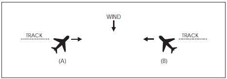
EXAMPLE-
In FIG 4-1-1 traffic information would be issued to the pilot of aircraft “A” as 12 o'clock. The actual position of the traffic as seen by the pilot of aircraft “A” would be 2 o'clock. Traffic information issued to aircraft “B” would also be given as 12 o'clock, but in this case, the pilot of “B” would see the traffic at 10 o'clock.
FIG 4-1-2
Induced Error in Position of Traffic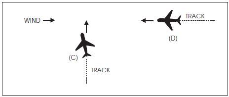
EXAMPLE-
In FIG 4-1-2 traffic information would be issued to the pilot of aircraft “C” as 2 o'clock. The actual position of the traffic as seen by the pilot of aircraft “C” would be 3 o'clock. Traffic information issued to aircraft “D” would be at an 11 o'clock position. Since it is not necessary for the pilot of aircraft “D” to apply wind correction (crab) to remain on track, the actual position of the traffic issued would be correct. Since the radar controller can only observe aircraft track (course) on the radar display, traffic advisories are issued accordingly, and pilots should give due consideration to this fact when looking for reported traffic.
-
Purpose of the Service
-
Safety Alert
A safety alert will be issued to pilots of aircraft being controlled by ATC if the controller is aware the aircraft is at an altitude which, in the controller's judgment, places the aircraft in unsafe proximity to terrain, obstructions or other aircraft. The provision of this service is contingent upon the capability of the controller to have an awareness of a situation involving unsafe proximity to terrain, obstructions and uncontrolled aircraft. The issuance of a safety alert cannot be mandated, but it can be expected on a reasonable, though intermittent basis. Once the alert is issued, it is solely the pilot's prerogative to determine what course of action, if any, to take. This procedure is intended for use in time critical situations where aircraft safety is in question. Noncritical situations should be handled via the normal traffic alert procedures.
-
Terrain or Obstruction Alert
-
Controllers will immediately issue an alert to the pilot of an aircraft under their control when they recognize that the aircraft is at an altitude which, in their judgment, may be in an unsafe proximity to terrain/obstructions. The primary method of detecting unsafe proximity is through Mode C automatic altitude reports.
EXAMPLE-
Low altitude alert Cessna Three Four Juliett, check your altitude immediately. And if the aircraft is not yet on final approach, the MVA (MEA/MIA/MOCA) in your area is six thousand.
- Most En Route and Terminal radar facilities have an automated function which, if operating, alerts controllers when a tracked Mode C equipped aircraft under their control is below or is predicted to be below a predetermined minimum safe altitude. This function, called Minimum Safe Altitude Warning (MSAW), is designed solely as a controller aid in detecting potentially unsafe aircraft proximity to terrain/obstructions. The radar facility will, when MSAW is operating, provide MSAW monitoring for all aircraft with an operating Mode C altitude encoding transponder that are tracked by the system and are:
- Due to the lack of terrain and obstacle clearance data, accurate automation databases may not be available for providing MSAW information to aircraft overflying Mexico and Canada. Air traffic facilities along the United States/Mexico/Canada borders may have MSAW computer processing inhibited where accurate terrain data is not available.
-
Controllers will immediately issue an alert to the pilot of an aircraft under their control when they recognize that the aircraft is at an altitude which, in their judgment, may be in an unsafe proximity to terrain/obstructions. The primary method of detecting unsafe proximity is through Mode C automatic altitude reports.
-
Aircraft Conflict Alert.
-
Controllers will immediately issue an alert to the pilot of an aircraft under their control if they are aware of another aircraft which is not under their control, at an altitude which, in the controller's judgment, places both aircraft in unsafe proximity to each other. With the alert, when feasible, the controller will offer the pilot the position of the traffic if time permits and an alternate course(s) of action. Any alternate course(s) of action the controller may recommend to the pilot will be predicated only on other traffic being worked by the controller.
EXAMPLE-
American Three, traffic alert, (position of traffic, if time permits), advise you turn right/left heading (degrees) and/or climb/descend to (altitude) immediately.
-
Controllers will immediately issue an alert to the pilot of an aircraft under their control if they are aware of another aircraft which is not under their control, at an altitude which, in the controller's judgment, places both aircraft in unsafe proximity to each other. With the alert, when feasible, the controller will offer the pilot the position of the traffic if time permits and an alternate course(s) of action. Any alternate course(s) of action the controller may recommend to the pilot will be predicated only on other traffic being worked by the controller.
-
Terrain or Obstruction Alert
-
Radar Assistance to VFR Aircraft
- Radar equipped FAA ATC facilities provide radar assistance and navigation service (vectors) to VFR aircraft provided the aircraft can communicate with the facility, are within radar coverage, and can be radar identified.
- Pilots should clearly understand that authorization to proceed in accordance with such radar navigational assistance does not constitute authorization for the pilot to violate CFRs. In effect, assistance provided is on the basis that navigational guidance information issued is advisory in nature and the job of flying the aircraft safely, remains with the pilot.
- In many cases, controllers will be unable to determine if flight into instrument conditions will result from their instructions. To avoid possible hazards resulting from being vectored into IFR conditions, pilots should keep controllers advised of the weather conditions in which they are operating and along the course ahead.
-
Radar navigation assistance (vectors) may be initiated by the controller when one of the following conditions exist:
- The controller suggests the vector and the pilot concurs.
- A special program has been established and vectoring service has been advertised.
- In the controller's judgment the vector is necessary for air safety.
- Radar navigation assistance (vectors) and other radar derived information may be provided in response to pilot requests. Many factors, such as limitations of radar, volume of traffic, communications frequency, congestion, and controller workload could prevent the controller from providing it. Controllers have complete discretion for determining if they are able to provide the service in a particular case. Their decision not to provide the service in a particular case is not subject to question.
-
Terminal Radar Services for VFR Aircraft
-
Basic Radar Service:
-
In addition to the use of radar for the control of IFR aircraft, all commissioned radar facilities provide the following basic radar services for VFR aircraft:
- Safety alerts.
- Traffic advisories.
- Limited radar vectoring (on a workload permitting basis).
-
Sequencing at locations where procedures have been established for this purpose and/or when covered by a Letter of Agreement.
NOTE-
When the stage services were developed, two basic radar services (traffic advisories and limited vectoring) were identified as “Stage I.” This definition became unnecessary and the term “Stage I” was eliminated from use. The term “Stage II” has been eliminated in conjunction with the airspace reclassification, and sequencing services to locations with local procedures and/or letters of agreement to provide this service have been included in basic services to VFR aircraft. These basic services will still be provided by all terminal radar facilities whether they include Class B, Class C, Class D or Class E airspace. “Stage III” services have been replaced with “Class B” and “TRSA” service where applicable.
- Vectoring service may be provided when requested by the pilot or with pilot concurrence when suggested by ATC.
- Pilots of arriving aircraft should contact approach control on the publicized frequency and give their position, altitude, aircraft call sign, type aircraft, radar beacon code (if transponder equipped), destination, and request traffic information.
- Approach control will issue wind and runway, except when the pilot states “have numbers” or this information is contained in the ATIS broadcast and the pilot states that the current ATIS information has been received. Traffic information is provided on a workload permitting basis. Approach control will specify the time or place at which the pilot is to contact the tower on local control frequency for further landing information. Radar service is automatically terminated and the aircraft need not be advised of termination when an arriving VFR aircraft receiving radar services to a tower-controlled airport where basic radar service is provided has landed, or to all other airports, is instructed to change to tower or advisory frequency. (See FAA Order JO 7110.65, Air Traffic Control, paragraph 5-1-9, Radar Service Termination.)
-
Sequencing for VFR aircraft is available at certain terminal locations (see locations listed in the Chart Supplement). The purpose of the service is to adjust the flow of arriving VFR and IFR aircraft into the traffic pattern in a safe and orderly manner and to provide radar traffic information to departing VFR aircraft. Pilot participation is urged but is not mandatory. Traffic information is provided on a workload permitting basis. Standard radar separation between VFR or between VFR and IFR aircraft is not provided.
- Pilots of arriving VFR aircraft should initiate radio contact on the publicized frequency with approach control when approximately 25 miles from the airport at which sequencing services are being provided. On initial contact by VFR aircraft, approach control will assume that sequencing service is requested. After radar contact is established, the pilot may use pilot navigation to enter the traffic pattern or, depending on traffic conditions, approach control may provide the pilot with routings or vectors necessary for proper sequencing with other participating VFR and IFR traffic en route to the airport. When a flight is positioned behind a preceding aircraft and the pilot reports having that aircraft in sight, the pilot will be instructed to follow the preceding aircraft. THE ATC INSTRUCTION TO FOLLOW THE PRECEDING AIRCRAFT DOES NOT AUTHORIZE THE PILOT TOCOMPLY WITH ANY ATC CLEARANCE OR INSTRUCTION ISSUED TO THE PRECEDING AIRCRAFT. If other “nonparticipating” or “local” aircraft are in the traffic pattern, the tower will issue a landing sequence. If an arriving aircraft does not want radar service, the pilot should state “NEGATIVE RADAR SERVICE” or make a similar comment, on initial contact with approach control.
-
Pilots of departing VFR aircraft are encouraged to request radar traffic information by notifying ground control, or where applicable, clearance delivery, on initial contact with their request and proposed direction of flight.
EXAMPLE-
Xray ground control, November One Eight Six, Cessna One Seventy Two, ready to taxi, VFR southbound at 2,500, have information bravo and request radar traffic information.
NOTE-
Following takeoff, the tower will advise when to contact departure control.
- Pilots of aircraft transiting the area and in radar contact/communication with approach control will receive traffic information on a controller workload permitting basis. Pilots of such aircraft should give their position, altitude, aircraft call sign, aircraft type, radar beacon code (if transponder equipped), destination, and/or route of flight.
-
In addition to the use of radar for the control of IFR aircraft, all commissioned radar facilities provide the following basic radar services for VFR aircraft:
-
TRSA Service (Radar Sequencing and Separation Service for VFR Aircraft in a TRSA).
- This service has been implemented at certain terminal locations. The service is advertised in the Chart Supplement. The purpose of this service is to provide separation between all participating VFR aircraft and all IFR aircraft operating within the airspace defined as the Terminal Radar Service Area (TRSA). Pilot participation is urged but is not mandatory.
- If any aircraft does not want the service, the pilot should state “NEGATIVE TRSA SERVICE” or make a similar comment, on initial contact with approach control or ground control, as appropriate.
- TRSAs are depicted on sectional aeronautical charts and listed in the Chart Supplement.
- While operating within a TRSA, pilots are provided TRSA service and separation as prescribed in this paragraph. In the event of a radar outage, separation and sequencing of VFR aircraft will be suspended as this service is dependent on radar. The pilot will be advised that the service is not available and issued wind, runway information, and the time or place to contact the tower. Traffic information will be provided on a workload permitting basis.
-
Visual separation is used when prevailing conditions permit and it will be applied as follows:
- When a VFR flight is positioned behind a preceding aircraft and the pilot reports having that aircraft in sight, the pilot will be instructed by ATC to follow the preceding aircraft. Radar service will be continued to the runway. THE ATC INSTRUCTION TO FOLLOW THE PRECEDING AIRCRAFT DOES NOT AUTHORIZE THE PILOT TO COMPLY WITH ANY ATC CLEARANCE OR INSTRUCTION ISSUED TO THE PRECEDING AIRCRAFT.
- If other “nonparticipating” or “local” aircraft are in the traffic pattern, the tower will issue a landing sequence.
- Departing VFR aircraft may be asked if they can visually follow a preceding departure out of the TRSA. The pilot will be instructed to follow the other aircraft provided that the pilot can maintain visual contact with that aircraft.
-
Participating VFR aircraft will be separated from IFR and other participating VFR aircraft by one of the following:
- 500 feet vertical separation.
- Visual separation.
- Target resolution (a process to ensure that correlated radar targets do not touch).
-
Participating pilots operating VFR in a TRSA:
- Must maintain an altitude when assigned by ATC unless the altitude assignment is to maintain at or below a specified altitude. ATC may assign altitudes for separation that do not conform to 14 CFR section 91.159. When the altitude assignment is no longer needed for separation or when leaving the TRSA, the instruction will be broadcast, “RESUME APPROPRIATE VFR ALTITUDES.” Pilots must then return to an altitude that conforms to 14 CFR section 91.159 as soon as practicable.
- When not assigned an altitude, the pilot should coordinate with ATC prior to any altitude change.
- Within the TRSA, traffic information on observed but unidentified targets will, to the extent possible, be provided to all IFR and participating VFR aircraft. The pilot will be vectored upon request to avoid the observed traffic, provided the aircraft to be vectored is within the airspace under the jurisdiction of the controller.
- Departing aircraft should inform ATC of their intended destination and/or route of flight and proposed cruising altitude.
- ATC will normally advise participating VFR aircraft when leaving the geographical limits of the TRSA. Radar service is not automatically terminated with this advisory unless specifically stated by the controller.
- Class C Service. This service provides, in addition to basic radar service, approved separation between IFR and VFR aircraft, and sequencing of VFR arrivals to the primary airport.
- Class B Service. This service provides, in addition to basic radar service, approved separation of aircraft based on IFR, VFR, and/or weight, and sequencing of VFR arrivals to the primary airport(s).
- PILOT RESPONSIBILITY. THESE SERVICES ARE NOT TO BE INTERPRETED AS RELIEVING PILOTS OF THEIR RESPONSIBILITIES TO SEE AND AVOID OTHER TRAFFIC OPERATING IN BASIC VFR WEATHER CONDITIONS, TO ADJUST THEIR OPERATIONS AND FLIGHT PATH AS NECESSARY TO PRECLUDE SERIOUS WAKE ENCOUNTERS, TO MAINTAIN APPROPRIATE TERRAIN AND OBSTRUCTION CLEARANCE, OR TO REMAIN IN WEATHER CONDITIONS EQUAL TO OR BETTER THAN THE MINIMUMS REQUIRED BY 14 CFR SECTION 91.155. WHENEVER COMPLIANCE WITH AN ASSIGNED ROUTE, HEADING AND/OR ALTITUDE IS LIKELY TO COMPROMISE PILOT RESPONSIBILITY RESPECTING TERRAIN AND OBSTRUCTION CLEARANCE, VORTEX EXPOSURE, AND WEATHER MINIMUMS, APPROACH CONTROL SHOULD BE SO ADVISED AND A REVISED CLEARANCE OR INSTRUCTION OBTAINED.
-
ATC services for VFR aircraft participating in terminal radar services are dependent on ATC radar. Services for VFR aircraft are not available during periods of a radar outage. The pilot will be advised when VFR services are limited or not available.
NOTE-
Class B and Class C airspace are areas of regulated airspace. The absence of ATC radar does not negate the requirement of an ATC clearance to enter Class B airspace or two way radio contact with ATC to enter Class C airspace.
-
Basic Radar Service:
-
Tower En Route Control (TEC)
- TEC is an ATC program to provide a service to aircraft proceeding to and from metropolitan areas. It links designated Approach Control Areas by a network of identified routes made up of the existing airway structure of the National Airspace System. The FAA initiated an expanded TEC program to include as many facilities as possible. The program's intent is to provide an overflow resource in the low altitude system which would enhance ATC services. A few facilities have historically allowed turbojets to proceed between certain city pairs, such as Milwaukee and Chicago, via tower en route and these locations may continue this service. However, the expanded TEC program will be applied, generally, for nonturbojet aircraft operating at and below 10,000 feet. The program is entirely within the approach control airspace of multiple terminal facilities. Essentially, it is for relatively short flights. Participating pilots are encouraged to use TEC for flights of two hours duration or less. If longer flights are planned, extensive coordination may be required within the multiple complex which could result in unanticipated delays.
- Pilots requesting TEC are subject to the same delay factor at the destination airport as other aircraft in the ATC system. In addition, departure and en route delays may occur depending upon individual facility workload. When a major metropolitan airport is incurring significant delays, pilots in the TEC program may want to consider an alternative airport experiencing no delay.
- There are no unique requirements upon pilots to use the TEC program. Normal flight plan filing procedures will ensure proper flight plan processing. Pilots should include the acronym “TEC” in the remarks section of the flight plan when requesting tower en route control.
- All approach controls in the system may not operate up to the maximum TEC altitude of 10,000 feet. IFR flight may be planned to any satellite airport in proximity to the major primary airport via the same routing.
-
Transponder and ADS-B Out Operation
-
General
- Pilots should be aware that proper application of transponder and ADS-B operating procedures will provide both VFR and IFR aircraft with a higher degree of safety while operating on the ground and airborne. Transponder/ADS-B panel designs differ; therefore, a pilot should be thoroughly familiar with the operation of their particular equipment to maximize its full potential. ADS-B Out, and transponders with altitude reporting mode turned ON (Mode C or S), substantially increase the capability of surveillance systems to see an aircraft. This provides air traffic controllers, as well as pilots of suitably equipped aircraft (TCAS and ADS-B In), increased situational awareness and the ability to identify potential traffic conflicts. Even VFR pilots who are not in contact with ATC will be afforded greater protection from IFR aircraft and VFR aircraft that are receiving traffic advisories. Nevertheless, pilots should never relax their visual scanning for other aircraft, and should include the ADS-B In display (if equipped) in their normal traffic scan.
- Air Traffic Control Radar Beacon System (ATCRBS) is similar to and compatible with military coded radar beacon equipment. Civil Mode A is identical to military Mode 3.
-
Transponder and ADS-B operations on the ground. Civil and military aircraft should operate with the transponder in the altitude reporting mode (consult the aircraft's flight manual to determine the specific transponder position to enable altitude reporting) and ADS-B Out transmissions enabled at all airports, any time the aircraft is positioned on any portion of the airport movement area. This includes all defined taxiways and runways. Pilots must pay particular attention to ATIS and airport diagram notations, General Notes (included on airport charts), and comply with directions pertaining to transponder and ADS-B usage. Generally, these directions are:
- Departures. Select the transponder mode which allows altitude reporting and enable ADS-B during pushback or taxi-out from parking spot. Select TA or TA/RA (if equipped with TCAS) when taking the active runway.
- Arrivals. If TCAS equipped, deselect TA or TA/RA upon leaving the active runway, but continue transponder and ADS-B transmissions in the altitude reporting mode. Select STBY or OFF for transponder and ADS-B upon arriving at the aircraft's parking spot or gate.
-
Transponder and ADS-B Operations While Airborne.
- Unless otherwise requested by ATC, aircraft equipped with an ATC transponder maintained in accordance with 14 CFR section 91.413 MUST operate with this equipment on the appropriate Mode 3/A code, or other code as assigned by ATC, and with altitude reporting enabled whenever in controlled airspace. If practicable, aircraft SHOULD operate with the transponder enabled in uncontrolled airspace.
- Aircraft equipped with ADS-B Out MUST operate with this equipment in the transmit mode at all times, unless otherwise requested by ATC.
-
Transponder and ADS-B Operation Under Visual Flight Rules (VFR).
- Unless otherwise instructed by an ATC facility, adjust transponder/ADS-B to reply on Mode 3/A Code 1200 regardless of altitude.
- When required to operate their transponder/ADS-B, pilots must always operate that equipment with altitude reporting enabled unless otherwise instructed by ATC or unless the installed equipment has not been tested and calibrated as required by 14 CFR section 91.217. If deactivation is required, turn off altitude reporting.
-
When participating in a VFR standard formation flight that is not receiving ATC services, only the lead aircraft should operate its transponder and ADS-B Out and squawk code 1203. Once established in formation, all other aircraft should squawk standby and disable ADS-B transmissions.
NOTE-
- If the formation flight is receiving ATC services, pilots can expect ATC to direct all non-lead aircraft to STOP Squawk, and should not do so until instructed.
- Firefighting aircraft not in contact with ATC may squawk 1255 in lieu of 1200 while en route to, from, or within the designated firefighting area(s).
- VFR aircraft flying authorized SAR missions for the USAF or USCG may be advised to squawk 1277 in lieu of 1200 while en route to, from, or within the designated search area.
- VFR gliders should squawk 1202 in lieu of 1200.
REFERENCE-
FAA Order JO 7110.66, National Beacon Code Allocation Plan (NBCAP).
- A pilot on an IFR flight who elects to cancel the IFR flight plan prior to reaching their destination, should adjust the transponder/ADS-B according to VFR operations.
- If entering a U.S. OFFSHORE AIRSPACE AREA from outside the U.S., the pilot should advise on first radio contact with a U.S. radar ATC facility that such equipment is available by adding “transponder” or “ADS-B” (if equipped) to the aircraft identification.
-
It should be noted by all users of ATC transponders and ADS-B Out systems that the surveillance coverage they can expect is limited to “line of sight” with ground radar and ADS-B radio sites. Low altitude or aircraft antenna shielding by the aircraft itself may result in reduced range or loss of aircraft contact. Though ADS-B often provides superior reception at low altitudes, poor coverage from any surveillance system can be improved by climbing to a higher altitude.
NOTE-
Pilots should refer to AIM, paragraph 4-5-7, Automatic Dependent Surveillance - Broadcast (ADS-B) Services, for a complete description of operating limitations and procedures.
-
Transponder/ADS-B Code Designation
-
For ATC to utilize one of the 4096 discrete codes, a four-digit code designation will be used; for example, code 2102 will be expressed as “TWO ONE ZERO TWO.”
NOTE-
Circumstances may occasionally require ATC to assign a non-discrete code; i.e., a code ending in “00.”
REFERENCE-
FAA Order JO 7110.66, National Beacon Code Allocation Plan (NBCAP).
-
For ATC to utilize one of the 4096 discrete codes, a four-digit code designation will be used; for example, code 2102 will be expressed as “TWO ONE ZERO TWO.”
-
Automatic Altitude Reporting
- Most transponders (Modes C and S) and all ADS-B Out systems are capable of automatic altitude reporting. This system converts aircraft altitude in 100-foot increments to coded digital information that is transmitted to the appropriate surveillance facility as well as to ADS-B In and TCAS systems.
-
Adjust the transponder/ADS-B to reply on the Mode 3/A code specified by ATC and with altitude reporting enabled, unless otherwise directed by ATC or unless the altitude reporting equipment has not been tested and calibrated as required by 14 CFR section 91.217. If deactivation is required by ATC, turn off the altitude reporting feature of your transponder/ADS-B. An instruction by ATC to “STOP ALTITUDE SQUAWK, ALTITUDE DIFFERS BY (number of feet) FEET,” may be an indication that the transmitted altitude information is incorrect, or that the aircraft's altimeter setting is incorrect. While an incorrect altimeter setting has no effect on the transmitted altitude information, it will cause the aircraft to fly at a true altitude different from the assigned altitude. When a controller indicates that an altitude readout is invalid, the pilot should verify that the aircraft altimeter is set correctly.
NOTE-
Altitude encoders are preset at standard atmospheric pressure. Local altimeter correction is applied by the surveillance facility before the altitude information is presented to ATC.
- Pilots should report exact altitude or flight level to the nearest hundred foot increment when establishing initial contact with an ATC facility. Exact altitude or flight level reports on initial contact provide ATC with information that is required prior to using automatically reported altitude information for separation purposes. This will significantly reduce altitude verification requests.
-
IDENT Feature
Transponder/ADS-B Out equipment must be operated only as specified by ATC. Activate the “IDENT” feature only when requested by ATC. -
Code Changes
- When making routine code changes, pilots should avoid inadvertent selection of Codes 7500, 7600 or 7700 thereby causing momentary false alarms at automated ground facilities. For example, when switching from Code 2700 to Code 7200, switch first to 2200 then to 7200, NOT to 7700 and then 7200. This procedure applies to nondiscrete Code 7500 and all discrete codes in the 7600 and 7700 series (i.e., 7600-7677, 7700-7777) which will trigger special indicators in automated facilities. Only nondiscrete Code 7500 will be decoded as the hijack code.
- Under no circumstances should a pilot of a civil aircraft operate the transponder on Code 7777. This code is reserved for military interceptor operations.
- Military pilots operating VFR or IFR within restricted/warning areas should adjust their transponders to Code 4000 unless another code has been assigned by ATC.
-
Mode C Transponder and ADS-B Out Requirements
- Specific details concerning requirements to carry and operate Mode C transponders and ADS-B Out, as well as exceptions and ATC authorized deviations from those requirements, are found in 14 CFR sections 91.215, 91.225, and 99.13.
-
In general, the CFRs require aircraft to be equipped with an operable Mode C transponder and ADS-B Out when operating:
- In Class A, Class B, or Class C airspace areas;
- Above the ceiling and within the lateral boundaries of Class B or Class C airspace up to 10,000 feet MSL;
- Class E airspace at and above 10,000 feet MSL within the 48 contiguous states and the District of Columbia, excluding the airspace at and below 2,500 feet AGL;
- Within 30 miles of a Class B airspace primary airport, below 10,000 feet MSL (commonly referred to as the “Mode C Veil”);
-
For ADS-B Out: Class E airspace at and above 3,000 feet MSL over the Gulf of America from the coastline of the United States out to 12 nautical miles.
NOTE-
The airspace described in (e) above is specified in 14 CFR § 91.225 for ADS-B Out requirements. However, 14 CFR § 91.215 does not include this airspace for ATC transponder requirements.
-
Transponder and ADS-B Out requirements do not apply to any aircraft that was not originally certificated with an electrical system, or that has not subsequently been certified with such a system installed, including balloons and gliders. These aircraft may conduct operations without a transponder or ADS-B Out when operating:
- Outside any Class B or Class C airspace area; and
- Below the altitude of the ceiling of a Class B or Class C airspace area designated for an airport, or 10,000 feet MSL, whichever is lower.
-
14 CFR section 99.13 requires all aircraft flying into, within, or across the contiguous U.S. ADIZ be equipped with a Mode C or Mode S transponder. Balloons, gliders and aircraft not equipped with an engine-driven electrical system are excepted from this requirement.
REFERENCE-
AIM, Chapter 5, Section 6, National Security and Interception Procedures.
- Pilots must ensure that their aircraft transponder/ADS-B is operating on an appropriate ATC-assigned VFR/IFR code with altitude reporting enabled when operating in such airspace. If in doubt about the operational status of either feature of your transponder while airborne, contact the nearest ATC facility or FSS and they will advise you what facility you should contact for determining the status of your equipment.
- In-flight requests for “immediate” deviation from the transponder requirements may be approved by controllers only for failed equipment, and only when the flight will continue IFR or when weather conditions prevent VFR descent and continued VFR flight in airspace not affected by the CFRs. All other requests for deviation should be made at least 1 hour before the proposed operation by contacting the nearest Flight Service or Air Traffic facility in person or by telephone. The nearest ARTCC will normally be the controlling agency and is responsible for coordinating requests involving deviations in other ARTCC areas.
- In-flight requests for “immediate” deviation from the ADS-B Out requirements may be approved by ATC only for failed equipment, and may be accommodated based on workload, alternate surveillance availability, or other factors. All other requests for deviation must be made at least 1 hour before the proposed operation, following the procedures contained in Advisory Circular (AC) 90-114, Automatic Dependent Surveillance-Broadcast Operations.
-
Cooperative Surveillance Phraseology. Air traffic controllers, both civil and military, will use the following phraseology when referring to operation of cooperative ATC surveillance equipment. Except as noted, the following ATC instructions do not apply to military transponders operating in other than Mode 3/A/C/S.
- SQUAWK (number).Operate radar beacon transponder/ADS-B on designated code with altitude reporting enabled.
- IDENT.Engage the “IDENT” feature (military I/P) of the transponder/ADS-B.
- SQUAWK (number) AND IDENT.Operate transponder/ADS-B on specified code with altitude reporting enabled, and engage the “IDENT” (military I/P) feature.
- SQUAWK STANDBY.Switch transponder/ADS-B to standby position.
- SQUAWK NORMAL. Resume normal transponder/ADS-B operation on previously assigned code. (Used after “SQUAWK STANDBY,” or by military after specific transponder tests).
- SQUAWK ALTITUDE.Activate Mode C with automatic altitude reporting.
- STOP ALTITUDE SQUAWK.Turn off automatic altitude reporting.
- STOP SQUAWK (Mode in use).Stop transponder and ADS-B Out transmissions, or switch off only specified mode of the aircraft transponder (military).
- SQUAWK MAYDAY.Operate transponder/ADS-B in the emergency position (Mode A Code 7700 for civil transponder. Mode 3 Code 7700 and emergency feature for military transponder.)
- SQUAWK VFR.Operate radar beacon transponder/ADS-B on Code 1200 in the Mode A/3, or other appropriate VFR code, with altitude reporting enabled.
-
General
-
Airport Reservation Operations and Special Traffic Management Programs
This section describes procedures for obtaining required airport reservations at airports designated by the FAA and for airports operating under Special Traffic Management Programs.
-
Slot Controlled Airports.
- The FAA may adopt rules to require advance reservations for unscheduled operations at certain airports. In addition to the information in the rules adopted by the FAA, a listing of the airports and relevant information will be maintained on the FAA website www.fly.faa.gov/ecvrs.
- The FAA has established an Airport Reservation Office (ARO) to receive and process reservations for unscheduled flights at the slot controlled airports. The ARO uses the Enhanced Computer Voice Reservation System (e-CVRS) to allocate reservations. Reservations will be available beginning 72 hours in advance of the operation at the slot controlled airport. Standby lists are not maintained. Flights with declared emergencies do not require reservations. Refer to the website for the current listing of slot controlled airports, limitations, and reservation procedures.
- For more detailed information on operations and reservation procedures at a Slot Controlled Airport, please see 14 CFR part 93, Subpart K - High Density Traffic Airports.
-
Special Traffic Management Programs (STMP).
- Special programs may be established when a location requires special traffic handling to accommodate above normal traffic demand (for example, EAA AirVenture Oshkosh, SUN 'n FUN Aerospace Expo) or reduced airport capacity (for example, airport runway/taxiway closures for airport construction). The special programs may remain in effect until the problem has been resolved or until local traffic management procedures can handle the volume and a need for special handling no longer exists.
- If an STMP is used to accommodate a special event, a domestic notice will be issued relaying the website address: www.fly.faa.gov/estmp. Domestic notice information includes: what airports are included in the STMP, the dates and times reservations are required, the time limits for reservation requests, the point of contact for reservations, and any other instructions.
-
Making Reservations. Detailed information and User Instruction Guides for using the Web reservation systems are available on the websites for the slot controlled airports (e-CVRS), www.fly.faa.gov/ecvrs; and STMPs (e-STMP), www.fly.faa.gov/estmp.
NOTE-
Users may contact the ARO at (540) 422-4246 if they have a problem with their reservation.
-
Slot Controlled Airports.
-
Requests for Waivers and Authorizations from Title 14, Code of Federal Regulations (14 CFR)
- Requests for a Certificate of Waiver or Authorization (FAA Form 7711-2), or requests for renewal of a waiver or authorization, may be accepted by any FAA facility and will be forwarded, if necessary, to the appropriate office having waiver authority.
- The grant of a Certificate of Waiver or Authorization from 14 CFR constitutes relief from specific regulations, to the degree and for the period of time specified in the certificate, and does not waive any state law or local ordinance. Should the proposed operations conflict with any state law or local ordinance, or require permission of local authorities or property owners, it is the applicant's responsibility to resolve the matter. The holder of a waiver is responsible for compliance with the terms of the waiver and its provisions.
- A waiver may be canceled at any time by the Administrator, the person authorized to grant the waiver, or the representative designated to monitor a specific operation. In such case either written notice of cancellation, or written confirmation of a verbal cancellation will be provided to the holder.
-
Weather Systems Processor
The Weather Systems Processor (WSP) was developed for use in the National Airspace System to provide weather processor enhancements to selected Airport Surveillance Radar (ASR)-9 facilities. The WSP provides Air Traffic with warnings of hazardous wind shear and microbursts. The WSP also provides users with terminal area 6-level weather, storm cell locations and movement, as well as the location and predicted future position and intensity of wind shifts that may affect airport operations.
Section 2. Radio Communications Phraseology and Techniques
-
General
- Radio communications are a critical link in the ATC system. The link can be a strong bond between pilot and controller or it can be broken with surprising speed and disastrous results. Discussion herein provides basic procedures for new pilots and also highlights safe operating concepts for all pilots.
- The single, most important thought in pilot‐controller communications is understanding. It is essential, therefore, that pilots acknowledge each radio communication with ATC by using the appropriate aircraft call sign. Brevity is important, and contacts should be kept as brief as possible, but controllers must know what you want to do before they can properly carry out their control duties. And you, the pilot, must know exactly what the controller wants you to do. Since concise phraseology may not always be adequate, use whatever words are necessary to get your message across. Pilots are to maintain vigilance in monitoring air traffic control radio communications frequencies for potential traffic conflicts with their aircraft especially when operating on an active runway and/or when conducting a final approach to landing.
- All pilots will find the Pilot/Controller Glossary very helpful in learning what certain words or phrases mean. Good phraseology enhances safety and is the mark of a professional pilot. Jargon, chatter, and “CB” slang have no place in ATC communications. The Pilot/Controller Glossary is the same glossary used in FAA Order JO 7110.65, Air Traffic Control. We recommend that it be studied and reviewed from time to time to sharpen your communication skills.
-
Radio Technique
- Listenbefore you transmit. Many times you can get the information you want through ATIS or by monitoring the frequency. Except for a few situations where some frequency overlap occurs, if you hear someone else talking, the keying of your transmitter will be futile and you will probably jam their receivers causing them to repeat their call. If you have just changed frequencies, pause, listen, and make sure the frequency is clear.
- Think before keying your transmitter. Know what you want to say and if it is lengthy; e.g., a flight plan or IFR position report, jot it down.
- The microphone should be very close to your lips and after pressing the mike button, a slight pause may be necessary to be sure the first word is transmitted. Speak in a normal, conversational tone.
- When you release the button, wait a few seconds before calling again. The controller or FSS specialist may be jotting down your number, looking for your flight plan, transmitting on a different frequency, or selecting the transmitter for your frequency.
- Be alert to the sounds or the lack of sounds in your receiver. Check your volume, recheck your frequency, and make sure that your microphone is not stuck in the transmit position. Frequency blockage can, and has, occurred for extended periods of time due to unintentional transmitter operation. This type of interference is commonly referred to as a “stuck mike,” and controllers may refer to it in this manner when attempting to assign an alternate frequency. If the assigned frequency is completely blocked by this type of interference, use the procedures described for en route IFR radio frequency outage to establish or reestablish communications with ATC.
- Be sure that you are within the performance range of your radio equipment and the ground station equipment. Remote radio sites do not always transmit and receive on all of a facility's available frequencies, particularly with regard to VOR sites where you can hear but not reach a ground station's receiver. Remember that higher altitudes increase the range of VHF “line of sight” communications.
-
Contact Procedures
-
Initial Contact.
-
The terms initial contact or initial callup means the first radio call you make to a given facility or the first call to a different controller or FSS specialist within a facility. Use the following format:
- Name of the facility being called;
- Your full aircraft identification as filed in the flight plan or as discussed in paragraph 4-2-4, Aircraft Call Signs;
- When operating on an airport surface, state your position.
- The type of message to follow or your request if it is short; and
-
The word “Over” if required.
EXAMPLE-
- “New York Radio, Mooney Three One One Echo.”
- “Columbia Ground, Cessna Three One Six Zero Foxtrot, south ramp, I-F-R Memphis.”
- “Miami Center, Baron Five Six Three Hotel, request V-F-R traffic advisories.”
-
Many FSSs are equipped with Remote Communications Outlets (RCOs) and can transmit on the same frequency at more than one location. The frequencies available at specific locations are indicated on charts above FSS communications boxes. To enable the specialist to utilize the correct transmitter, advise the location and the frequency on which you expect a reply.
EXAMPLE-
St. Louis FSS can transmit on frequency 122.3 at either Farmington, Missouri, or Decatur, Illinois, if you are in the vicinity of Decatur, your callup should be “Saint Louis radio, Piper Six Niner Six Yankee, receiving Decatur One Two Two Point Three.”
-
If radio reception is reasonably assured, inclusion of your request, your position or altitude, and the phrase “(ATIS) Information Charlie received” in the initial contact helps decrease radio frequency congestion. Use discretion; do not overload the controller with information unneeded or superfluous. If you do not get a response from the ground station, recheck your radios or use another transmitter, but keep the next contact short.
EXAMPLE-
“Atlanta Center, Duke Four One Romeo, request V-F-R traffic advisories, Twenty Northwest Rome, seven thousand five hundred, over.”
-
The terms initial contact or initial callup means the first radio call you make to a given facility or the first call to a different controller or FSS specialist within a facility. Use the following format:
-
Initial Contact When Your Transmitting and Receiving Frequencies are Different.
-
If you are attempting to establish contact with a ground station and you are receiving on a different frequency than that transmitted, indicate the VOR name or the frequency on which you expect a reply. Most FSSs and control facilities can transmit on several VOR stations in the area. Use the appropriate FSS call sign as indicated on charts.
EXAMPLE-
New York FSS transmits on the Kennedy, the Hampton, and the Calverton VORTACs. If you are in the Calverton area, your callup should be “New York radio, Cessna Three One Six Zero Foxtrot, receiving Calverton V-O-R, over.”
- If the chart indicates FSS frequencies above the VORTAC or in the FSS communications boxes, transmit or receive on those frequencies nearest your location.
- When unable to establish contact and you wish to call any ground station, use the phrase “ANY RADIO (tower) (station), GIVE CESSNA THREE ONE SIX ZERO FOXTROT A CALL ON (frequency) OR (V-O-R).” If an emergency exists or you need assistance, so state.
-
If you are attempting to establish contact with a ground station and you are receiving on a different frequency than that transmitted, indicate the VOR name or the frequency on which you expect a reply. Most FSSs and control facilities can transmit on several VOR stations in the area. Use the appropriate FSS call sign as indicated on charts.
-
Subsequent Contacts and Responses to Callup from a Ground Facility.
Use the same format as used for the initial contact except you should state your message or request with the callup in one transmission. The ground station name and the word “Over” may be omitted if the message requires an obvious reply and there is no possibility for misunderstandings. You should acknowledge all callups or clearances unless the controller or FSS specialist advises otherwise. There are some occasions when controllers must issue time‐critical instructions to other aircraft, and they may be in a position to observe your response, either visually or on radar. If the situation demands your response, take appropriate action or immediately advise the facility of any problem. Acknowledge with your aircraft identification, either at the beginning or at the end of your transmission, and one of the words “Wilco,” “Roger,” “Affirmative,” “Negative,” or other appropriate remarks; e.g., “PIPER TWO ONE FOUR LIMA, ROGER.” If you have been receiving services; e.g., VFR traffic advisories and you are leaving the area or changing frequencies, advise the ATC facility and terminate contact. -
Acknowledgement of Frequency Changes.
- When advised by ATC to change frequencies, acknowledge the instruction. If you select the new frequency without an acknowledgement, the controller's workload is increased because there is no way of knowing whether you received the instruction or have had radio communications failure.
-
At times, a controller/specialist may be working a sector with multiple frequency assignments. In order to eliminate unnecessary verbiage and to free the controller/specialist for higher priority transmissions, the controller/specialist may request the pilot “(Identification), change to my frequency 134.5.” This phrase should alert the pilot that the controller/specialist is only changing frequencies, not controller/specialist, and that initial callup phraseology may be abbreviated.
EXAMPLE-
“United Two Twenty-Two on one three four point five” or “one three four point five, United Two Twenty-Two.”
-
Compliance with Frequency Changes.
When instructed by ATC to change frequencies, select the new frequency as soon as possible unless instructed to make the change at a specific time, fix, or altitude. A delay in making the change could result in an untimely receipt of important information. If you are instructed to make the frequency change at a specific time, fix, or altitude, monitor the frequency you are on until reaching the specified time, fix, or altitudes unless instructed otherwise by ATC.REFERENCE-
AIM, Para 5-3-1, ARTCC Communications.
-
Initial Contact.
-
Aircraft Call Signs
-
Precautions in the Use of Call Signs.
-
Improper use of call signs can result in pilots executing a clearance intended for another aircraft. Call signs should never be abbreviated on an initial contact or at any time when other aircraft call signs have similar numbers/sounds or identical letters/number; e.g., Cessna 6132F, Cessna 1622F, Baron 123F, Cherokee 7732F, etc.
EXAMPLE-
Assume that a controller issues an approach clearance to an aircraft at the bottom of a holding stack and an aircraft with a similar call sign (at the top of the stack) acknowledges the clearance with the last two or three numbers of the aircraft's call sign. If the aircraft at the bottom of the stack did not hear the clearance and intervene, flight safety would be affected, and there would be no reason for either the controller or pilot to suspect that anything is wrong. This kind of “human factors” error can strike swiftly and is extremely difficult to rectify.
- Pilots, therefore, must be certain that aircraft identification is complete and clearly identified before taking action on an ATC clearance. ATC specialists will not abbreviate call signs of air carrier or other civil aircraft having authorized call signs. ATC specialists may initiate abbreviated call signs of other aircraft by using the prefix and the last three digits/letters of the aircraft identification after communications are established. The pilot may use the abbreviated call sign in subsequent contacts with the ATC specialist. When aware of similar/identical call signs, ATC specialists will take action to minimize errors by emphasizing certain numbers/letters, by repeating the entire call sign, by repeating the prefix, or by asking pilots to use a different call sign temporarily. Pilots should use the phrase “VERIFY CLEARANCE FOR (your complete call sign)” if doubt exists concerning proper identity.
-
Civil aircraft pilots should state the aircraft type, model or manufacturer's name, followed by the digits/letters of the registration number. When the aircraft manufacturer's name or model is stated, the prefix “N” is dropped; e.g., Aztec Two Four Six Four Alpha.
EXAMPLE-
- Bonanza Six Five Five Golf.
- Breezy Six One Three Romeo Experimental (omit “Experimental” after initial contact).
-
Air Taxi or other commercial operators not having FAA authorized call signs should prefix their normal identification with the phonetic word “Tango.”
EXAMPLE-
Tango Aztec Two Four Six Four Alpha.
-
Air carriers and commuter air carriers having FAA authorized call signs should identify themselves by stating the complete call sign (using group form for the numbers) and the word “super” or “heavy” if appropriate.
EXAMPLE-
- United Twenty-Five Heavy.
- Midwest Commuter Seven Eleven.
- Military aircraft use a variety of systems including serial numbers, word call signs, and combinations of letters/numbers. Examples include Army Copter 48931; Air Force 61782; REACH 31792; Pat 157; Air Evac 17652; Navy Golf Alfa Kilo 21; Marine 4 Charlie 36, etc.
-
Improper use of call signs can result in pilots executing a clearance intended for another aircraft. Call signs should never be abbreviated on an initial contact or at any time when other aircraft call signs have similar numbers/sounds or identical letters/number; e.g., Cessna 6132F, Cessna 1622F, Baron 123F, Cherokee 7732F, etc.
-
Air Ambulance Flights.
Because of the priority afforded air ambulance flights in the ATC system, extreme discretion is necessary when using the term “MEDEVAC.” It is only intended for those missions of an urgent medical nature and to be utilized only for that portion of the flight requiring priority handling. It is important for ATC to be aware of a flight's MEDEVAC status, and it is the pilot's responsibility to ensure that this information is provided to ATC.-
To receive priority handling from ATC, the pilot must verbally identify the flight in radio transmissions by stating “MEDEVAC” followed by the FAA authorized call sign (ICAO 3LD, US Special, or local) or the aircraft civil “N” registration numbers/letters.
EXAMPLE-
If the aircraft identification of the flight indicates DAL51, the pilot states “MEDEVAC Delta Fifty One.”
If the aircraft identification of the flight indicates MDSTR1, the pilot states “MEDEVAC Medstar One.”
If the aircraft identification of the flight indicates N123G or LN123G, the pilot states “MEDEVAC One Two Three Golf”.
- If requested by the pilot, ATC will provide additional assistance (e.g., landline notifications) to expedite ground handling of patients, vital organs, or urgently needed medical materials. When possible make these requests to ATC via methods other than through ATC radio frequencies.
-
MEDEVAC flights may include:
- Civilian air ambulance flights responding to medical emergencies (e.g., first call to an accident scene, carrying patients, organ donors, organs, or other urgently needed lifesaving medical material).
- Air carrier and air taxi flights responding to medical emergencies. The nature of these medical emergency flights usually concerns the transportation of urgently needed lifesaving medical materials or vital organs, but can include inflight medical emergencies. It is imperative that the company/pilot determine, by the nature/urgency of the specific medical cargo, if priority ATC assistance is required.
-
When filing a flight plan, pilots may include “L” for MEDEVAC with the aircraft registration letters/digits and/or include “MEDEVAC” in Item 11 (Remarks) of the flight plan or Item 18 (Other Information) of an international flight plan. However, ATC will only use these flight plan entries for informational purposes or as a visual indicator. ATC will only provide priority handling when the pilot verbally identifies the “MEDEVAC” status of the flight as described in subparagraph b1 above.
NOTE-
Civilian air ambulance aircraft operating VFR and without a filed flight plan are eligible for priority handling in accordance with subparagraph b1 above.
- ATC will also provide priority handling to HOSP and AIR EVAC flights when verbally requested. These aircraft may file “HOSP” or “AIR EVAC” in either Item 11 (Remarks) of the flight plan or Item 18 of an international flight plan. For aircraft identification in radio transmissions, civilian pilots will use normal call signs when filing “HOSP” and military pilots will use the “EVAC” call sign.
-
To receive priority handling from ATC, the pilot must verbally identify the flight in radio transmissions by stating “MEDEVAC” followed by the FAA authorized call sign (ICAO 3LD, US Special, or local) or the aircraft civil “N” registration numbers/letters.
-
Student Pilots Radio Identification.
-
The FAA desires to help student pilots in acquiring sufficient practical experience in the environment in which they will be required to operate. To receive additional assistance while operating in areas of concentrated air traffic, student pilots need only identify themselves as a student pilot during their initial call to an FAA radio facility.
EXAMPLE-
Dayton tower, Fleetwing One Two Three Four, student pilot.
- This special identification will alert FAA ATC personnel and enable them to provide student pilots with such extra assistance and consideration as they may need. It is recommended that student pilots identify themselves as such, on initial contact with each clearance delivery prior to taxiing, ground control, tower, approach and departure control frequency, or FSS contact.
-
The FAA desires to help student pilots in acquiring sufficient practical experience in the environment in which they will be required to operate. To receive additional assistance while operating in areas of concentrated air traffic, student pilots need only identify themselves as a student pilot during their initial call to an FAA radio facility.
-
Precautions in the Use of Call Signs.
-
Description of Interchange or Leased Aircraft
- Controllers issue traffic information based on familiarity with airline equipment and color/markings. When an air carrier dispatches a flight using another company's equipment and the pilot does not advise the terminal ATC facility, the possible confusion in aircraft identification can compromise safety.
-
Pilots flying an “interchange” or “leased” aircraft not bearing the colors/markings of the company operating the aircraft should inform the terminal ATC facility on first contact the name of the operating company and trip number, followed by the company name as displayed on the aircraft, and aircraft type.
EXAMPLE-
Air Cal Three Eleven, United (interchange/lease), Boeing Seven Two Seven.
-
Ground Station Call Signs
Pilots, when calling a ground station, should begin with the name of the facility being called followed by the type of the facility being called as indicated in TBL 4-2-1.
TBL 4-2-1
Calling a Ground StationFacility
Call Sign
Airport UNICOM
“Shannon UNICOM”
FAA Flight Service Station
“Chicago Radio”
Airport Traffic Control Tower
“Augusta Tower”
Clearance Delivery Position (IFR)
“Dallas Clearance Delivery”
Ground Control Position in Tower
“Miami Ground”
Radar or Nonradar Approach Control Position
“Oklahoma City Approach”
Radar Departure Control Position
“St. Louis Departure”
FAA Air Route Traffic Control Center
“Washington Center”
-
Phonetic Alphabet
The International Civil Aviation Organization (ICAO) phonetic alphabet is used by FAA personnel when communications conditions are such that the information cannot be readily received without their use. ATC facilities may also request pilots to use phonetic letter equivalents when aircraft with similar sounding identifications are receiving communications on the same frequency. Pilots should use the phonetic alphabet when identifying their aircraft during initial contact with air traffic control facilities. Additionally, use the phonetic equivalents for single letters and to spell out groups of letters or difficult words during adverse communications conditions. (See TBL 4-2-2.)
TBL 4-2-2
Phonetic Alphabet/Morse CodeCharacter
Morse Code
Telephony
Phonic
(Pronunciation)A
● —
Alfa
(AL-FAH)
B
— ● ● ●
Bravo
(BRAH-VOH)
C
— ● — ●
Charlie
(CHAR-LEE) or
(SHAR-LEE)D
— ● ●
Delta
(DELL-TAH)
E
●
Echo
(ECK-OH)
F
● ● — ●
Foxtrot
(FOKS-TROT)
G
— — ●
Golf
(GOLF)
H
● ● ● ●
Hotel
(HOH-TEL)
I
● ●
India
(IN-DEE-AH)
J
● — — —
Juliett
(JEW-LEE-ETT)
K
— ● —
Kilo
(KEY-LOH)
L
● — ● ●
Lima
(LEE-MAH)
M
— —
Mike
(MIKE)
N
— ●
November
(NO-VEM-BER)
O
— — —
Oscar
(OSS-CAH)
P
● — — ●
Papa
(PAH-PAH)
Q
— — ● —
Quebec
(KEH-BECK)
R
● — ●
Romeo
(ROW-ME-OH)
S
● ● ●
Sierra
(SEE-AIR-RAH)
T
—
Tango
(TANG-GO)
U
● ● —
Uniform
(YOU-NEE-FORM) or
(OO-NEE-FORM)V
● ● ● —
Victor
(VIK-TAH)
W
● — —
Whiskey
(WISS-KEY)
X
— ● ● —
Xray
(ECKS-RAY)
Y
— ● — —
Yankee
(YANG-KEY)
Z
— — ● ●
Zulu
(ZOO-LOO)
1
● — — — —
One
(WUN)
2
● ● — — —
Two
(TOO)
3
● ● ● — —
Three
(TREE)
4
● ● ● ● —
Four
(FOW-ER)
5
● ● ● ● ●
Five
(FIFE)
6
— ● ● ● ●
Six
(SIX)
7
— — ● ● ●
Seven
(SEV-EN)
8
— — — ● ●
Eight
(AIT)
9
— — — — ●
Nine
(NIN-ER)
0
— — — — —
Zero
(ZEE-RO)
-
Figures
-
Figures indicating hundreds and thousands in round number, as for ceiling heights, and upper wind levels up to 9,900 must be spoken in accordance with the following.
EXAMPLE-
- 500 . . . . . . . .five hundred
- 4,500 . . . . . . . .four thousand five hundred
-
Numbers above 9,900 must be spoken by separating the digits preceding the word “thousand.”
EXAMPLE-
- 10,000 . . . . . . . .one zero thousand
- 13,500 . . . . . . . .one three thousand five hundred
-
Transmit airway or jet route numbers as follows.
EXAMPLE-
- V12. . . . . . . .Victor Twelve
- J533. . . . . . . .J Five Thirty-Three
-
All other numbers must be transmitted by pronouncing each digit.
EXAMPLE-
10 . . . . . . . .one zero
-
When a radio frequency contains a decimal point, the decimal point is spoken as “POINT.”
EXAMPLE-
122.1. . . . . . . .one two two point one
NOTE-
ICAO procedures require the decimal point be spoken as “DECIMAL.” The FAA will honor such usage by military aircraft and all other aircraft required to use ICAO procedures.
-
Figures indicating hundreds and thousands in round number, as for ceiling heights, and upper wind levels up to 9,900 must be spoken in accordance with the following.
-
Altitudes and Flight Levels
-
Up to but not including 18,000 feet MSL, state the separate digits of the thousands plus the hundreds if appropriate.
EXAMPLE-
- 12,000 . . . . . . . .one two thousand
- 12,500 . . . . . . . .one two thousand five hundred
-
At and above 18,000 feet MSL (FL 180), state the words “flight level” followed by the separate digits of the flight level.
EXAMPLE-
- 190 . . . . . . . .Flight Level One Niner Zero
- 275 . . . . . . . .Flight Level Two Seven Five
-
Up to but not including 18,000 feet MSL, state the separate digits of the thousands plus the hundreds if appropriate.
-
Directions
The three digits of bearing, course, heading, or wind direction should always be magnetic. The word “true” must be added when it applies.
EXAMPLE-
- (Magnetic course) 005 . . . . . . . .zero zero five
- (True course) 050 . . . . . . . .zero five zero true
- (Magnetic bearing) 360 . . . . . . . .three six zero
- (Magnetic heading) 100 . . . . . . . .heading one zero zero
- (Wind direction) 220 . . . . . . . .wind two two zero
-
Speeds
The separate digits of the speed followed by the word “KNOTS.” Except, controllers may omit the word “KNOTS” when using speed adjustment procedures; e.g., “REDUCE/INCREASE SPEED TO TWO FIVE ZERO.”
EXAMPLE-
(Speed) 250 . . . . . . . . two five zero knots
The separate digits of the Mach Number preceded by “Mach.”
(Speed) 190 . . . . . . . . one niner zero knotsEXAMPLE-
(Mach number) 1.5 . . . . . . . .Mach one point five
(Mach number) 0.64. . . . . . . .Mach point six four
(Mach number) 0.7. . . . . . . .Mach point seven -
Time
-
FAA uses Coordinated Universal Time (UTC) for all operations. The word “local” or the time zone equivalent must be used to denote local when local time is given during radio and telephone communications. The term “Zulu” may be used to denote UTC.
EXAMPLE-
0920 UTC. . . . . . . .zero niner two zero,
zero one two zero pacific or local,
or one twenty AM -
To convert from Standard Time to Coordinated Universal Time:
TBL 4-2-3
Standard Time to Coordinated Universal TimeEastern Standard Time
Add 5 hours
Central Standard Time
Add 6 hours
Mountain Standard Time
Add 7 hours
Pacific Standard Time
Add 8 hours
Alaska Standard Time
Add 9 hours
Hawaii Standard Time
Add 10 hours
NOTE-
For daylight time, subtract 1 hour.
-
A reference may be made to local daylight or standard time utilizing the 24-hour clock system. The hour is indicated by the first two figures and the minutes by the last two figures.
EXAMPLE-
0000 . . . . . . . . zero zero zero zero
0920 . . . . . . . . zero niner two zero - Time may be stated in minutes only (two figures) in radiotelephone communications when no misunderstanding is likely to occur.
-
Current time in use at a station is stated in the nearest quarter minute in order that pilots may use this information for time checks. Fractions of a quarter minute less than 8 seconds are stated as the preceding quarter minute; fractions of a quarter minute of 8 seconds or more are stated as the succeeding quarter minute.
EXAMPLE-
0929:05 . . . . . . . .time, zero niner two niner
0929:10 . . . . . . . .time, zero niner two niner and one-quarter
-
FAA uses Coordinated Universal Time (UTC) for all operations. The word “local” or the time zone equivalent must be used to denote local when local time is given during radio and telephone communications. The term “Zulu” may be used to denote UTC.
-
Communications with Tower when Aircraft Transmitter or Receiver or Both are Inoperative
-
Arriving Aircraft.
-
Receiver inoperative.
-
If you have reason to believe your receiver is inoperative, remain outside or above the Class D surface area until the direction and flow of traffic has been determined; then, advise the tower of your type aircraft, position, altitude, intention to land, and request that you be controlled with light signals.
REFERENCE-
AIM, Para 4-3-13, Traffic Control Light Signals.
- When you are approximately 3 to 5 miles from the airport, advise the tower of your position and join the airport traffic pattern. From this point on, watch the tower for light signals. Thereafter, if a complete pattern is made, transmit your position downwind and/or turning base leg.
-
If you have reason to believe your receiver is inoperative, remain outside or above the Class D surface area until the direction and flow of traffic has been determined; then, advise the tower of your type aircraft, position, altitude, intention to land, and request that you be controlled with light signals.
- Transmitter inoperative. Remain outside or above the Class D surface area until the direction and flow of traffic has been determined; then, join the airport traffic pattern. Monitor the primary local control frequency as depicted on Sectional Charts for landing or traffic information, and look for a light signal which may be addressed to your aircraft. During hours of daylight, acknowledge tower transmissions or light signals by rocking your wings. At night, acknowledge by blinking the landing or navigation lights. To acknowledge tower transmissions during daylight hours, hovering helicopters will turn in the direction of the controlling facility and flash the landing light. While in flight, helicopters should show their acknowledgement of receiving a transmission by making shallow banks in opposite directions. At night, helicopters will acknowledge receipt of transmissions by flashing either the landing or the search light.
- Transmitter and receiver inoperative. Remain outside or above the Class D surface area until the direction and flow of traffic has been determined; then, join the airport traffic pattern and maintain visual contact with the tower to receive light signals. Acknowledge light signals as noted above.
-
Receiver inoperative.
-
Departing Aircraft. If you experience radio failure prior to leaving the parking area, make every effort to have the equipment repaired. If you are unable to have the malfunction repaired, call the tower by telephone and request authorization to depart without two‐way radio communications. If tower authorization is granted, you will be given departure information and requested to monitor the tower frequency or watch for light signals as appropriate. During daylight hours, acknowledge tower transmissions or light signals by moving the ailerons or rudder. At night, acknowledge by blinking the landing or navigation lights. If radio malfunction occurs after departing the parking area, watch the tower for light signals or monitor tower frequency.
REFERENCE-
14 CFR Section 91.125 and 14 CFR Section 91.129.
-
Arriving Aircraft.
-
Communications for VFR Flights
-
FSSs and Supplemental Weather Service Locations (SWSL) are allocated frequencies for different functions; for example, in Alaska, certain FSSs provide Local Airport Advisory on 123.6 MHz or other frequencies which can be found in the Chart Supplement. If you are in doubt as to what frequency to use, 122.2 MHz is assigned to the majority of FSSs as a common en route simplex frequency.
NOTE-
In order to expedite communications, state the frequency being used and the aircraft location during initial callup.
EXAMPLE-
Dayton radio, November One Two Three Four Five on one two two point two, over Springfield V-O-R, over.
- Certain VOR voice channels are being utilized for recorded broadcasts; for example, ATIS. These services and appropriate frequencies are listed in the Chart Supplement. On VFR flights, pilots are urged to monitor these frequencies. When in contact with a control facility, notify the controller if you plan to leave the frequency to monitor these broadcasts.
-
FSSs and Supplemental Weather Service Locations (SWSL) are allocated frequencies for different functions; for example, in Alaska, certain FSSs provide Local Airport Advisory on 123.6 MHz or other frequencies which can be found in the Chart Supplement. If you are in doubt as to what frequency to use, 122.2 MHz is assigned to the majority of FSSs as a common en route simplex frequency.
Section 3. Airport Operations
-
General
Increased traffic congestion, aircraft in climb and descent attitudes, and pilot preoccupation with cockpit duties are some factors that increase the hazardous accident potential near the airport. The situation is further compounded when the weather is marginal, that is, just meeting VFR requirements. Pilots must be particularly alert when operating in the vicinity of an airport. This section defines some rules, practices, and procedures that pilots should be familiar with and adhere to for safe airport operations.
-
Airports with an Operating Control Tower
- When operating at an airport where traffic control is being exercised by a control tower, pilots are required to maintain two-way radio contact with the tower while operating within the Class B, Class C, and Class D surface area unless the tower authorizes otherwise. Initial callup should be made about 15 miles from the airport. Unless there is a good reason to leave the tower frequency before exiting the Class B, Class C, and Class D surface areas, it is a good operating practice to remain on the tower frequency for the purpose of receiving traffic information. In the interest of reducing tower frequency congestion, pilots are reminded that it is not necessary to request permission to leave the tower frequency once outside of Class B, Class C, and Class D surface areas. Not all airports with an operating control tower will have Class D airspace. These airports do not have weather reporting which is a requirement for surface based controlled airspace, previously known as a control zone. The controlled airspace over these airports will normally begin at 700 feet or 1,200 feet above ground level and can be determined from the visual aeronautical charts. Pilots are expected to use good operating practices and communicate with the control tower as described in this section.
-
When necessary, the tower controller will issue clearances or other information for aircraft to generally follow the desired flight path (traffic patterns) when flying in Class B, Class C, and Class D surface areas and the proper taxi routes when operating on the ground. If not otherwise authorized or directed by the tower, pilots of fixed-wing aircraft approaching to land must circle the airport to the left. Pilots approaching to land in a helicopter must avoid the flow of fixed-wing traffic. However, in all instances, an appropriate clearance must be received from the tower before landing.
FIG 4-3-1
Components of a Traffic Pattern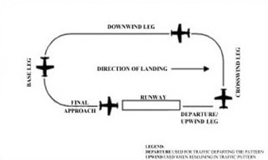
NOTE-
This diagram is intended only to illustrate terminology used in identifying various components of a traffic pattern. It should not be used as a reference or guide on how to enter a traffic pattern.
-
The following terminology for the various components of a traffic pattern has been adopted as standard for use by control towers and pilots (See FIG 4-3-1):
- Departure. The flight path that begins after takeoff and continues straight ahead along the extended runway centerline. The departure climb continues until reaching a point at least 1/2 mile beyond the departure end of the runway and within 300 feet of the traffic pattern altitude.
- Upwind leg. A flight path that begins after departure and continues straight ahead along the extended runway centerline. Upwind leg is an extension of departure and is used when issuing control instructions for separation, spacing, or sequencing.
- Crosswind leg. A flight path at right angles to the landing runway off its takeoff end.
- Downwind leg. A flight path parallel to the landing runway in the opposite direction of landing.
- Base leg. A flight path at right angles to the landing runway off its approach end and extending from the downwind leg to the intersection of the extended runway centerline.
- Final approach. A flight path in the direction of landing along the extended runway centerline from the base leg to the runway.
-
Many towers are equipped with a tower radar display. The radar uses are intended to enhance the effectiveness and efficiency of the local control, or tower, position. They are not intended to provide radar services or benefits to pilots except as they may accrue through a more efficient tower operation. The four basic uses are:
- To determine an aircraft's exact location.This is accomplished by radar identifying the VFR aircraft through any of the techniques available to a radar position, such as having the aircraft squawk ident. Once identified, the aircraft's position and spatial relationship to other aircraft can be quickly determined, and standard instructions regarding VFR operation in Class B, Class C, and Class D surface areas will be issued. Once initial radar identification of a VFR aircraft has been established and the appropriate instructions have been issued, radar monitoring may be discontinued; the reason being that the local controller's primary means of surveillance in VFR conditions is visually scanning the airport and local area.
- To provide radar traffic advisories. Radar traffic advisories may be provided to the extent that the local controller is able to monitor the radar display. Local control has primary control responsibilities to the aircraft operating on the runways, which will normally supersede radar monitoring duties.
-
To provide a direction or suggested heading. The local controller may provide pilots flying VFR with generalized instructions which will facilitate operations; e.g., “PROCEED SOUTHWESTBOUND, ENTER A RIGHT DOWNWIND RUNWAY THREE ZERO,” or provide a suggested heading to establish radar identification or as an advisory aid to navigation; e.g., “SUGGESTED HEADING TWO TWO ZERO, FOR RADAR IDENTIFICATION.” In both cases, the instructions are advisory aids to the pilot flying VFR and are not radar vectors.
NOTE-
Pilots have complete discretion regarding acceptance of the suggested headings or directions and have sole responsibility for seeing and avoiding other aircraft.
-
To provide information and instructions to aircraft operating within Class B, Class C, and Class D surface areas. In an example of this situation, the local controller would use the radar to advise a pilot on an extended downwind when to turn base leg.
NOTE-
The above tower radar applications are intended to augment the standard functions of the local control position. There is no controller requirement to maintain constant radar identification. In fact, such a requirement could compromise the local controller's ability to visually scan the airport and local area to meet FAA responsibilities to the aircraft operating on the runways and within the Class B, Class C, and Class D surface areas. Normally, pilots will not be advised of being in radar contact since that continued status cannot be guaranteed and since the purpose of the radar identification is not to establish a link for the provision of radar services.
- A few of the radar equipped towers are authorized to use the radar to ensure separation between aircraft in specific situations, while still others may function as limited radar approach controls. The various radar uses are strictly a function of FAA operational need. The facilities may be indistinguishable to pilots since they are all referred to as tower and no publication lists the degree of radar use. Therefore, when in communication with a tower controller who may have radar available, do not assume that constant radar monitoring and complete ATC radar services are being provided.
-
Traffic Patterns
-
It is recommended that aircraft enter the airport traffic pattern at one of the following altitudes listed below. These altitudes should be maintained unless another traffic pattern altitude is published in the Chart Supplement or unless otherwise required by the applicable distance from cloud criteria (14 CFR section 91.155). (See FIG 4-3-2 and FIG 4-3-3):
- Propeller-driven aircraft enter the traffic pattern at 1,000 feet above ground level (AGL).
- Large and turbine-powered aircraft enter the traffic pattern at an altitude of not less than 1,500 feet AGL or 500 feet above the established pattern altitude.
- Helicopters operating in the traffic pattern may fly a pattern similar to the fixed-wing aircraft pattern, but at a lower altitude (500 AGL) and closer to the runway. This pattern may be on the opposite side of the runway from fixed-wing traffic when airspeed requires or for practice power-off landings (autorotation) and if local policy permits. Landings not to the runway must avoid the flow of fixed wing traffic.
- A pilot may vary the size of the traffic pattern depending on the aircraft's performance characteristics. Pilots of en route aircraft should be constantly alert for aircraft in traffic patterns and avoid these areas whenever possible.
- Unless otherwise indicated, all turns in the traffic pattern must be made to the left, except for helicopters, as applicable.
-
On Sectional, Aeronautical, and VFR Terminal Area Charts, right traffic patterns are indicated at public-use and joint-use airports with the abbreviation “RP” (for Right Pattern), followed by the appropriate runway number(s) at the bottom of the airport data block.
EXAMPLE-
RP 9, 18, 22R
NOTE-
- Pilots are encouraged to use the standard traffic pattern. However, those pilots who choose to execute a straight-in approach, maneuvering for and execution of the approach should not disrupt the flow of arriving and departing traffic. Likewise, pilots operating in the traffic pattern should be alert at all times for aircraft executing straight-in approaches.
REFERENCE-
AC 90-66, Non-Towered Airport Flight Operations.
- *RP indicates special conditions exist and refers pilots to the Chart Supplement.
- Right traffic patterns are not shown at airports with full-time control towers.
-
Wind conditions affect all airplanes in varying degrees. Figure 4-3-4 is an example of a chart used to determine the headwind, crosswind, and tailwind components based on wind direction and velocity relative to the runway. Pilots should refer to similar information provided by the aircraft manufacturer when determining these wind components.
FIG 4-3-2
Traffic Pattern Operations Single Runway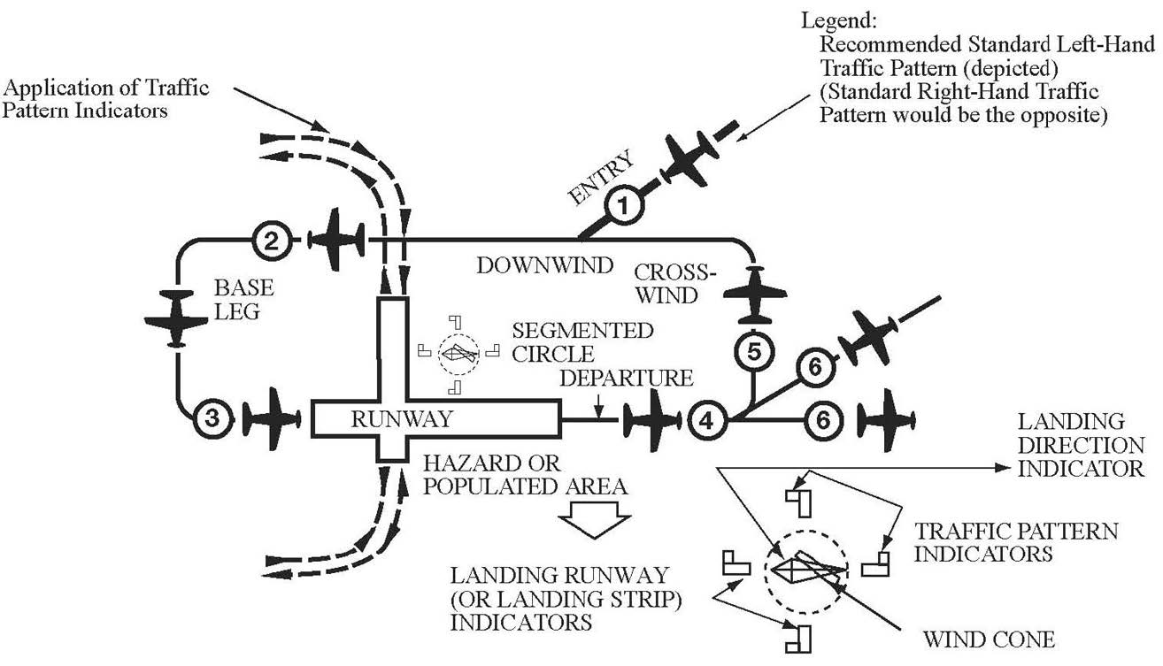
EXAMPLE-
Key to traffic pattern operations- Enter pattern in level flight, abeam the midpoint of the runway, at pattern altitude.
- Maintain pattern altitude until abeam approach end of the landing runway on downwind leg.
- Complete turn to final at least 1/4 mile from the runway.
- Continue straight ahead until beyond departure end of runway.
- If remaining in the traffic pattern, commence turn to crosswind leg beyond the departure end of the runway within 300 feet of pattern altitude.
- If departing the traffic pattern, continue straight out, or exit with a 45 degree turn (to the left when in a left-hand traffic pattern; to the right when in a right-hand traffic pattern) beyond the departure end of the runway, after reaching pattern altitude.
FIG 4-3-3
Traffic Pattern Operations Parallel Runways
EXAMPLE-
Key to traffic pattern operations- Enter pattern in level flight, abeam the midpoint of the runway, at pattern altitude.
- Maintain pattern altitude until abeam approach end of the landing runway on downwind leg.
- Complete turn to final at least 1/4 mile from the runway.
- Continue straight ahead until beyond departure end of runway.
- If remaining in the traffic pattern, commence turn to crosswind leg beyond the departure end of the runway within 300 feet of pattern altitude.
- If departing the traffic pattern, continue straight out, or exit with a 45 degree turn (to the left when in a left-hand traffic pattern; to the right when in a right-hand traffic pattern) beyond the departure end of the runway, after reaching pattern altitude.
- Do not overshoot final or continue on a track which will penetrate the final approach of the parallel runway.
- Do not continue on a track which will penetrate the departure path of the parallel runway.
FIG 4-3-4
Headwind/Tailwind/Crosswind Component Calculator
-
It is recommended that aircraft enter the airport traffic pattern at one of the following altitudes listed below. These altitudes should be maintained unless another traffic pattern altitude is published in the Chart Supplement or unless otherwise required by the applicable distance from cloud criteria (14 CFR section 91.155). (See FIG 4-3-2 and FIG 4-3-3):
-
Visual Indicators at Airports Without an Operating Control Tower
-
At those airports without an operating control tower, a segmented circle visual indicator system, if installed, is designed to provide traffic pattern information.
REFERENCE-
AIM, Para 4-1-9, Traffic Advisory Practices at Airports Without Operating Control Towers.
-
The segmented circle system consists of the following components:
- The segmented circle. Located in a position affording maximum visibility to pilots in the air and on the ground and providing a centralized location for other elements of the system.
- The wind direction indicator. A wind cone, wind sock, or wind tee installed near the operational runway to indicate wind direction. The large end of the wind cone/wind sock points into the wind as does the large end (cross bar) of the wind tee. In lieu of a tetrahedron and where a wind sock or wind cone is collocated with a wind tee, the wind tee may be manually aligned with the runway in use to indicate landing direction. These signaling devices may be located in the center of the segmented circle and may be lighted for night use. Pilots are cautioned against using a tetrahedron to indicate wind direction.
- The landing direction indicator. A tetrahedron is installed when conditions at the airport warrant its use. It may be used to indicate the direction of landings and takeoffs. A tetrahedron may be located at the center of a segmented circle and may be lighted for night operations. The small end of the tetrahedron points in the direction of landing. Pilots are cautioned against using a tetrahedron for any purpose other than as an indicator of landing direction. Further, pilots should use extreme caution when making runway selection by use of a tetrahedron in very light or calm wind conditions as the tetrahedron may not be aligned with the designated calm-wind runway. At airports with control towers, the tetrahedron should only be referenced when the control tower is not in operation. Tower instructions supersede tetrahedron indications.
- Landing strip indicators. Installed in pairs as shown in the segmented circle diagram and used to show the alignment of landing strips.
- Traffic pattern indicators. Arranged in pairs in conjunction with landing strip indicators and used to indicate the direction of turns when there is a variation from the normal left traffic pattern. (If there is no segmented circle installed at the airport, traffic pattern indicators may be installed on or near the end of the runway.)
- Preparatory to landing at an airport without a control tower, or when the control tower is not in operation, pilots should concern themselves with the indicator for the approach end of the runway to be used. When approaching for landing, all turns must be made to the left unless a traffic pattern indicator indicates that turns should be made to the right. If the pilot will mentally enlarge the indicator for the runway to be used, the base and final approach legs of the traffic pattern to be flown immediately become apparent. Similar treatment of the indicator at the departure end of the runway will clearly indicate the direction of turn after takeoff.
- When two or more aircraft are approaching an airport for the purpose of landing, the pilot of the aircraft at the lower altitude has the right-of-way over the pilot of the aircraft at the higher altitude. However, the pilot operating at the lower altitude should not take advantage of another aircraft, which is on final approach to land, by cutting in front of, or overtaking that aircraft.
-
At those airports without an operating control tower, a segmented circle visual indicator system, if installed, is designed to provide traffic pattern information.
-
Unexpected Maneuvers in the Airport Traffic Pattern
There have been several incidents in the vicinity of controlled airports that were caused primarily by aircraft executing unexpected maneuvers. ATC service is based upon observed or known traffic and airport conditions. Controllers establish the sequence of arriving and departing aircraft by requiring them to adjust flight as necessary to achieve proper spacing. These adjustments can only be based on observed traffic, accurate pilot reports, and anticipated aircraft maneuvers. Pilots are expected to cooperate so as to preclude disrupting traffic flows or creating conflicting patterns. The pilot-in-command of an aircraft is directly responsible for and is the final authority as to the operation of the aircraft. On occasion it may be necessary for pilots to maneuver their aircraft to maintain spacing with the traffic they have been sequenced to follow. The controller can anticipate minor maneuvering such as shallow “S” turns. The controller cannot, however, anticipate a major maneuver such as a 360 degree turn. If a pilot makes a 360 degree turn after obtaining a landing sequence, the result is usually a gap in the landing interval and, more importantly, it causes a chain reaction which may result in a conflict with following traffic and an interruption of the sequence established by the tower or approach controller. Should a pilot decide to make maneuvering turns to maintain spacing behind a preceding aircraft, the pilot should always advise the controller if at all possible. Except when requested by the controller or in emergency situations, a 360 degree turn should never be executed in the traffic pattern or when receiving radar service without first advising the controller.
-
Use of Runways/Declared Distances
-
Runways are identified by numbers that indicate the nearest 10-degree increment of the azimuth of the runway centerline. For example, where the magnetic azimuth is 183 degrees, the runway designation would be 18; for a magnetic azimuth of 87 degrees, the runway designation would be 9. For a magnetic azimuth ending in the number 5, such as 185, the runway designation could be either 18 or 19. Wind direction issued by the tower is also magnetic and wind velocity is in knots.
NOTE-
- At airports with multiple parallel runways whose magnetic azimuths are identical, each runway number will be supplemented by a letter and shown from left to right when viewed from the direction of approach.
- When multiple parallel runways at the same airport are separated by a large distance, such as by a central terminal or several terminals, the runways may be designated as non-parallel runways to avoid pilot confusion.
REFERENCE-
AC 150/5340-1, Standards for Airport Markings, Para 2.3.5, Characteristics.
-
Airport proprietors are responsible for taking the lead in local aviation noise control. Accordingly, they may propose specific noise abatement plans to the FAA. If approved, these plans are applied in the form of Formal or Informal Runway Use Programs for noise abatement purposes.
REFERENCE-
P/CG Term - RUNWAY USE PROGRAM.
-
ATC will assign the runway/s most nearly aligned with the wind when 5 knots or more, or the “calm wind” runway when less than 5 knots unless:
- Use of another runway is operationally advantageous, or
-
A Runway Use Program is in effect.
NOTE-
Tailwind and crosswind considerations take precedence over delay/capacity considerations, and noise abatement operations/procedures.
REFERENCE-
FAA Order JO 7110.65, Para 3-5-1, Selection.
-
ATC will assign the runway/s most nearly aligned with the wind when 5 knots or more, or the “calm wind” runway when less than 5 knots unless:
-
If a pilot prefers to use a runway different from that specified, the pilot is expected to advise ATC. ATC may honor such requests as soon as is operationally practicable. ATC will advise pilots when the requested runway is noise sensitive. When use of a runway other than the one assigned is requested, pilot cooperation is encouraged to preclude disruption of traffic flows or the creation of conflicting patterns.
REFERENCE-
FAA Order JO 7110.65, Para 3-5-1, Selection.
-
Declared Distances.
- Declared distances for a runway represent the maximum distances available and suitable for meeting takeoff and landing distance performance requirements. These distances are determined in accordance with FAA runway design standards by adding to the physical length of paved runway any clearway or stopway and subtracting from that sum any lengths necessary to obtain the standard runway safety areas, runway object free areas, or runway protection zones. As a result of these additions and subtractions, the declared distances for a runway may be more or less than the physical length of the runway as depicted on aeronautical charts and related publications, or available in electronic navigation databases provided by either the U.S. Government or commercial companies.
-
All 14 CFR part 139 airports report declared distances for each runway. Other airports may also report declared distances for a runway if necessary to meet runway design standards or to indicate the presence of a clearway or stopway. Where reported, declared distances for each runway end are published in the Chart Supplement. For runways without published declared distances, the declared distances may be assumed to be equal to the physical length of the runway unless there is a displaced landing threshold, in which case the Landing Distance Available (LDA) is shortened by the amount of the threshold displacement.
NOTE-
A symbol
 is shown on U.S. Government charts to indicate that runway declared distance information is available (See appropriate Chart Supplement, Chart Supplement Alaska or Pacific).
-
The FAA uses the following definitions for runway declared distances (See FIG 4-3-5):
REFERENCE-
P/CG Term - “ACCELERATE-STOP DISTANCE AVAILABLE,” “LANDING DISTANCE AVAILABLE,” “TAKEOFF DISTANCE AVAILABLE,” “TAKEOFF RUN AVAILABLE,” ” STOPWAY,” AND “CLEARWAY.”
-
Takeoff Run Available (TORA) - The runway length declared available and suitable for the ground run of an airplane taking off.
The TORA is typically the physical length of the runway, but it may be shorter than the runway length if necessary to satisfy runway design standards. For example, the TORA may be shorter than the runway length if a portion of the runway must be used to satisfy runway protection zone requirements. -
Takeoff Distance Available (TODA) - The takeoff run available plus the length of any remaining runway or clearway beyond the far end of the takeoff run available.
The TODA is the distance declared available for satisfying takeoff distance requirements for airplanes where the certification and operating rules and available performance data allow for the consideration of a clearway in takeoff performance computations.NOTE-
The length of any available clearway will be included in the TODA published in the entry for that runway end within the Chart Supplement.
-
Accelerate-Stop Distance Available (ASDA) - The runway plus stopway length declared available and suitable for the acceleration and deceleration of an airplane aborting a takeoff.
The ASDA may be longer than the physical length of the runway when a stopway has been designated available by the airport operator, or it may be shorter than the physical length of the runway if necessary to use a portion of the runway to satisfy runway design standards; for example, where the airport operator uses a portion of the runway to achieve the runway safety area requirement. ASDA is the distance used to satisfy the airplane accelerate-stop distance performance requirements where the certification and operating rules require accelerate-stop distance computations.NOTE-
The length of any available stopway will be included in the ASDA published in the entry for that runway end within the Chart Supplement.
-
Landing Distance Available (LDA) - The runway length declared available and suitable for a landing airplane.
The LDA may be less than the physical length of the runway or the length of the runway remaining beyond a displaced threshold if necessary to satisfy runway design standards;for example, where the airport operator uses a portion of the runway to achieve the runway safety area requirement.
Although some runway elements (such as stopway length and clearway length) may be available information, pilots must use the declared distances determined by the airport operator and not attempt to independently calculate declared distances by adding those elements to the reported physical length of the runway.
-
Takeoff Run Available (TORA) - The runway length declared available and suitable for the ground run of an airplane taking off.
- The airplane operating rules and/or the airplane operating limitations establish minimum distance requirements for takeoff and landing and are based on performance data supplied in the Airplane Flight Manual or Pilot's Operating Handbook. The minimum distances required for takeoff and landing obtained either in planning prior to takeoff or in performance assessments conducted at the time of landing must fall within the applicable declared distances before the pilot can accept that runway for takeoff or landing.
-
Runway design standards may impose restrictions on the amount of runway available for use in takeoff and landing that are not apparent from the reported physical length of the runway or from runway markings and lighting. The runway elements of Runway Safety Area (RSA), Runway Object Free Area (ROFA), and Runway Protection Zone (RPZ) may reduce a runway's declared distances to less than the physical length of the runway at geographically constrained airports (See FIG 4-3-6). When considering the amount of runway available for use in takeoff or landing performance calculations, the declared distances published for a runway must always be used in lieu of the runway's physical length.
REFERENCE-
AC 150/5300-13, Airport Design.
-
While some runway elements associated with declared distances may be identifiable through runway markings or lighting (for example, a displaced threshold or a stopway), the individual declared distance limits are not marked or otherwise identified on the runway. An aircraft is not prohibited from operating beyond a declared distance limit during the takeoff, landing, or taxi operation provided the runway surface is appropriately marked as usable runway (See FIG 4-3-6). The following examples clarify the intent of this paragraph.
REFERENCE-
AIM, Para 2-3-3, Runway Markings.
AC 150/5340-1, Standards for Airport Markings.EXAMPLE-
- The declared LDA for runway 9 must be used when showing compliance with the landing distance requirements of the applicable airplane operating rules and/or airplane operating limitations or when making a before landing performance assessment. The LDA is less than the physical runway length, not only because of the displaced threshold, but also because of the subtractions necessary to meet the RSA beyond the far end of the runway. However, during the actual landing operation, it is permissible for the airplane to roll beyond the unmarked end of the LDA.
- The declared ASDA for runway 9 must be used when showing compliance with the accelerate-stop distance requirements of the applicable airplane operating rules and/or airplane operating limitations. The ASDA is less than the physical length of the runway due to subtractions necessary to achieve the full RSA requirement. However, in the event of an aborted takeoff, it is permissible for the airplane to roll beyond the unmarked end of the ASDA as it is brought to a full-stop on the remaining usable runway.
FIG 4-3-5
Declared Distances with Full-Standard Runway Safety Areas, Runway Object Free Areas, and Runway Protection Zones
FIG 4-3-6
Effects of a Geographical Constraint on a Runway's Declared Distances
NOTE-
A runway's RSA begins a set distance prior to the threshold and will extend a set distance beyond the end of the runway depending on the runway's design criteria. If these required lengths cannot be achieved, the ASDA and/or LDA will be reduced as necessary to obtain the required lengths to the extent practicable.
-
The FAA uses the following definitions for runway declared distances (See FIG 4-3-5):
-
Runways are identified by numbers that indicate the nearest 10-degree increment of the azimuth of the runway centerline. For example, where the magnetic azimuth is 183 degrees, the runway designation would be 18; for a magnetic azimuth of 87 degrees, the runway designation would be 9. For a magnetic azimuth ending in the number 5, such as 185, the runway designation could be either 18 or 19. Wind direction issued by the tower is also magnetic and wind velocity is in knots.
-
Low Level Wind Shear/Microburst Detection Systems
Low Level Wind Shear Alert System (LLWAS), Terminal Doppler Weather Radar (TDWR), Weather Systems Processor (WSP), and Integrated Terminal Weather System (ITWS) display information on hazardous wind shear and microburst activity in the vicinity of an airport to air traffic controllers who relay this information to pilots.
-
LLWAS provides wind shear alert and gust front information but does not provide microburst alerts. The LLWAS is designed to detect low level wind shear conditions around the periphery of an airport. It does not detect wind shear beyond that limitation. Controllers will provide this information to pilots by giving the pilot the airport wind followed by the boundary wind.
EXAMPLE-
Wind shear alert, airport wind 230 at 8, south boundary wind 170 at 20.
-
LLWAS “network expansion,” (LLWAS NE) and LLWAS Relocation/Sustainment (LLWAS-RS) are systems integrated with TDWR. These systems provide the capability of detecting microburst alerts and wind shear alerts. Controllers will issue the appropriate wind shear alerts or microburst alerts. In some of these systems controllers also have the ability to issue wind information oriented to the threshold or departure end of the runway.
EXAMPLE-
Runway 17 arrival microburst alert, 40 knot loss 3 mile final.
REFERENCE-
AIM, Para 7-1-24, Microbursts.
- More advanced systems are in the field or being developed such as ITWS. ITWS provides alerts for microbursts, wind shear, and significant thunderstorm activity. ITWS displays wind information oriented to the threshold or departure end of the runway.
- The WSP provides weather processor enhancements to selected Airport Surveillance Radar (ASR)-9 facilities. The WSP provides Air Traffic with detection and alerting of hazardous weather such as wind shear, microbursts, and significant thunderstorm activity. The WSP displays terminal area 6 level weather, storm cell locations and movement, as well as the location and predicted future position and intensity of wind shifts that may affect airport operations. Controllers will receive and issue alerts based on Areas Noted for Attention (ARENA). An ARENA extends on the runway center line from a 3 mile final to the runway to a 2 mile departure.
- An airport equipped with the LLWAS, ITWS, or WSP is so indicated in the Chart Supplement under Weather Data Sources for that particular airport.
-
LLWAS provides wind shear alert and gust front information but does not provide microburst alerts. The LLWAS is designed to detect low level wind shear conditions around the periphery of an airport. It does not detect wind shear beyond that limitation. Controllers will provide this information to pilots by giving the pilot the airport wind followed by the boundary wind.
-
Braking Action Reports and Advisories
- When available, ATC furnishes pilots the quality of braking action received from pilots. The quality of braking action is described by the terms “good,” “good to medium,” “medium,” “medium to poor,” “poor,” and “nil.” When pilots report the quality of braking action by using the terms noted above, they should use descriptive terms that are easily understood, such as, “braking action poor the first/last half of the runway,” together with the particular type of aircraft.
-
FICON NOTAMs will provide contaminant measurements for paved runways; however, a FICON NOTAM for braking action will only be used for non-paved runway surfaces, taxiways, and aprons. These NOTAMs are classified according to the most critical term (“good to medium,” “medium,” “medium to poor,” and “poor”).
- FICON NOTAM reporting of a braking condition for paved runway surfaces is not permissible by Federally Obligated Airports or those airports certificated under 14 CFR part 139.
- A “NIL” braking condition at these airports must be mitigated by closure of the affected surface. Do not include the type of vehicle in the FICON NOTAM.
- When tower controllers receive runway braking action reports which include the terms medium, poor, or nil, or whenever weather conditions are conducive to deteriorating or rapidly changing runway braking conditions, the tower will include on the ATIS broadcast the statement, “BRAKING ACTION ADVISORIES ARE IN EFFECT.”
- During the time that braking action advisories are in effect, ATC will issue the most recent braking action report for the runway in use to each arriving and departing aircraft. Pilots should be prepared for deteriorating braking conditions and should request current runway condition information if not issued by controllers. Pilots should also be prepared to provide a descriptive runway condition report to controllers after landing.
-
Runway Condition Reports
- Aircraft braking coefficient is dependent upon the surface friction between the tires on the aircraft wheels and the pavement surface. Less friction means less aircraft braking coefficient and less aircraft braking response.
-
Runway condition code (RwyCC) values range from 1 (poor) to 6 (dry). For frozen contaminants on runway surfaces, a runway condition code reading of 4 indicates the level when braking deceleration or directional control is between good and medium.
NOTE-
A RwyCC of “0” is used to delineate a braking action report of NIL and is prohibited from being reported in a FICON NOTAM.
-
Airport management should conduct runway condition assessments on wet runways or runways covered with compacted snow and/or ice.
-
Numerical readings may be obtained by using the Runway Condition Assessment Matrix (RCAM). The RCAM provides the airport operator with data to complete the report that includes the following:
- Runway(s) in use
- Time of the assessment
- Runway condition codes for each zone (touchdown, mid-point, roll-out)
- Pilot-reported braking action report (if available)
- The contaminant (for example, wet snow, dry snow, slush, ice, etc.)
-
Assessments for each zone (see 4-3-9c1(c)) will be issued in the direction of takeoff and landing on the runway, ranging from “1” to “6” to describe contaminated surfaces.
NOTE-
A RwyCC of “0” is used to delineate a braking action report of NIL and is prohibited from being reported in a FICON NOTAM.
- When any 1 or more runway condition codes are reported as less than 6, airport management must notify ATC for dissemination to pilots.
- Controllers will not issue runway condition codes when all 3 segments of a runway are reporting values of 6.
-
Numerical readings may be obtained by using the Runway Condition Assessment Matrix (RCAM). The RCAM provides the airport operator with data to complete the report that includes the following:
- When runway condition code reports are provided by airport management, the ATC facility providing approach control or local airport advisory must provide the report to all pilots.
- Pilots should use runway condition code information with other knowledge including aircraft performance characteristics, type, and weight, previous experience, wind conditions, and aircraft tire type (such as bias ply vs. radial constructed) to determine runway suitability.
-
The Runway Condition Assessment Matrix identifies the descriptive terms “good,” “good to medium,” “medium,” “medium to poor,” “poor,” and “nil” used in braking action reports.
REFERENCE-
Advisory Circular AC 91-79, Mitigating the Risks of a Runway Overrun Upon Landing, Appendix 1.
FIG 4-3-7
Runway Condition Assessment Matrix (RCAM)
-
Intersection Takeoffs
- In order to enhance airport capacities, reduce taxiing distances, minimize departure delays, and provide for more efficient movement of air traffic, controllers may initiate intersection takeoffs as well as approve them when the pilot requests. If for ANY reason a pilot prefers to use a different intersection or the full length of the runway or desires to obtain the distance between the intersection and the runway end, THE PILOT IS EXPECTED TO INFORM ATC ACCORDINGLY.
-
Pilots are expected to assess the suitability of an intersection for use at takeoff during their preflight planning. They must consider the resultant length reduction to the published runway length and to the published declared distances from the intersection intended to be used for takeoff. The minimum runway required for takeoff must fall within the reduced runway length and the reduced declared distances before the intersection can be accepted for takeoff.
REFERENCE-
AIM, Para 4-3-6, Use of Runways/Declared Distances.
-
Controllers will issue the measured distance from the intersection to the runway end rounded “down” to the nearest 50 feet to any pilot who requests and to all military aircraft, unless use of the intersection is covered in appropriate directives. Controllers, however, will not be able to inform pilots of the distance from the intersection to the end of any of the published declared distances.
REFERENCE-
FAA Order JO 7110.65, Para 3-7-1, Ground Traffic Movement.
- An aircraft is expected to taxi to (but not onto) the end of the assigned runway unless prior approval for an intersection departure is received from ground control.
-
Pilots should state their position on the airport when calling the tower for takeoff from a runway intersection.
EXAMPLE-
Cleveland Tower, Apache Three Seven Two Two Papa, at the intersection of taxiway Oscar and runway two three right, ready for departure.
- Controllers are required to separate small aircraft that are departing from an intersection on the same runway (same or opposite direction) behind a large nonheavy aircraft (except B757), by ensuring that at least a 3-minute interval exists between the time the preceding large aircraft has taken off and the succeeding small aircraft begins takeoff roll. The 3-minute separation requirement will also be applied to small aircraft with a maximum certificated takeoff weight of 12,500 pounds or less departing behind a small aircraft with a maximum certificated takeoff weight of more than 12,500 pounds. To inform the pilot of the required 3-minute hold, the controller will state, “Hold for wake turbulence.” If after considering wake turbulence hazards, the pilot feels that a lesser time interval is appropriate, the pilot may request a waiver to the 3-minute interval. To initiate such a request, simply say “Request waiver to 3-minute interval” or a similar statement. Controllers may then issue a takeoff clearance if other traffic permits, since the pilot has accepted the responsibility for wake turbulence separation.
- The 3-minute interval is not required when the intersection is 500 feet or less from the departure point of the preceding aircraft and both aircraft are taking off in the same direction. Controllers may permit the small aircraft to alter course after takeoff to avoid the flight path of the preceding departure.
- A 4-minute interval is mandatory for small, large, and heavy aircraft behind a super aircraft. The 3-minute interval is mandatory behind a heavy aircraft in all cases, and for small aircraft behind a B757.
-
Pilot Responsibilities When Conducting Land and Hold Short Operations (LAHSO)
- LAHSO is an acronym for “Land and Hold Short Operations.” These operations include landing and holding short of an intersecting runway, an intersecting taxiway, or some other designated point on a runway other than an intersecting runway or taxiway. (See FIG 4-3-8, FIG 4-3-9, FIG 4-3-10.)
-
Pilot Responsibilities and Basic Procedures.
- LAHSO is an air traffic control procedure that requires pilot participation to balance the needs for increased airport capacity and system efficiency, consistent with safety. This procedure can be done safely provided pilots and controllers are knowledgeable and understand their responsibilities. The following paragraphs outline specific pilot/operator responsibilities when conducting LAHSO.
- At controlled airports, air traffic may clear a pilot to land and hold short. Pilots may accept such a clearance provided that the pilot-in-command determines that the aircraft can safely land and stop within the Available Landing Distance (ALD). ALD data are published in the Chart Supplementand in the U.S.Terminal Procedures Publications.Controllers will also provide ALD data upon request. Student pilots or pilots not familiar with LAHSO should not participate in the program.
- The pilot-in-command has the final authority to accept or decline any land and hold short clearance. The safety and operation of the aircraft remain the responsibility of the pilot. Pilots are expected to decline a LAHSO clearance if they determine it will compromise safety.
-
To conduct LAHSO, pilots should become familiar with all available information concerning LAHSO at their destination airport. Pilots should have, readily available, the published ALD and runway slope information for all LAHSO runway combinations at each airport of intended landing. Additionally, knowledge about landing performance data permits the pilot to readily determine that the ALD for the assigned runway is sufficient for safe LAHSO. As part of a pilot's preflight planning process, pilots should determine if their destination airport has LAHSO. If so, their preflight planning process should include an assessment of which LAHSO combinations would work for them given their aircraft's required landing distance. Good pilot decision making is knowing in advance whether one can accept a LAHSO clearance if offered.
FIG 4-3-8
Land and Hold Short of an Intersecting Runway
EXAMPLE-
FIG 4-3-10 - holding short at a designated point may be required to avoid conflicts with the runway safety area/flight path of a nearby runway.
NOTE-
Each figure shows the approximate location of LAHSO markings, signage, and in-pavement lighting when installed.
REFERENCE-
AIM, Chapter 2, Aeronautical Lighting and Other Airport Visual Aids.
FIG 4-3-9
Land and Hold Short of an Intersecting Taxiway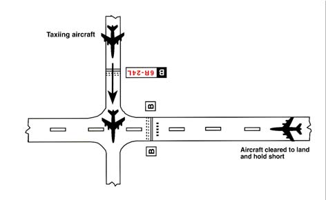
FIG 4-3-10
Land and Hold Short of a Designated Point on a Runway Other Than an Intersecting Runway or Taxiway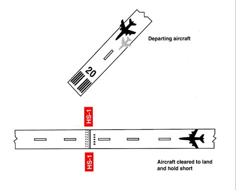
- If, for any reason, such as difficulty in discerning the location of a LAHSO intersection, wind conditions, aircraft condition, etc., the pilot elects to request to land on the full length of the runway, to land on another runway, or to decline LAHSO, a pilot is expected to promptly inform air traffic, ideally even before the clearance is issued. A LAHSO clearance, once accepted, must be adhered to, just as any other ATC clearance, unless an amended clearance is obtained or an emergency occurs. A LAHSO clearance does not preclude a rejected landing.
- A pilot who accepts a LAHSO clearance should land and exit the runway at the first convenient taxiway (unless directed otherwise) before reaching the hold short point. Otherwise, the pilot must stop and hold at the hold short point. If a rejected landing becomes necessary after accepting a LAHSO clearance, the pilot should maintain safe separation from other aircraft or vehicles, and should promptly notify the controller.
- Controllers need a full read back of all LAHSO clearances. Pilots should read back their LAHSO clearance and include the words, “HOLD SHORT OF (RUNWAY/TAXIWAY/OR POINT)” in their acknowledgment of all LAHSO clearances. In order to reduce frequency congestion, pilots are encouraged to read back the LAHSO clearance without prompting. Don't make the controller have to ask for a read back!
-
LAHSO Situational Awareness
- Situational awareness is vital to the success of LAHSO. Situational awareness starts with having current airport information in the cockpit, readily accessible to the pilot. (An airport diagram assists pilots in identifying their location on the airport, thus reducing requests for “progressive taxi instructions” from controllers.)
-
Situational awareness includes effective pilot-controller radio communication. ATC expects pilots to specifically acknowledge and read back all LAHSO clearances as follows:
EXAMPLE-
ATC: “(Aircraft ID) cleared to land runway six right, hold short of taxiway bravo for crossing traffic (type aircraft).”
Aircraft: “(Aircraft ID), wilco, cleared to land runway six right to hold short of taxiway bravo.”
ATC: “(Aircraft ID) cross runway six right at taxiway bravo, landing aircraft will hold short.”
Aircraft: “(Aircraft ID), wilco, cross runway six right at bravo, landing traffic (type aircraft) to hold.” - For those airplanes flown with two crewmembers, effective intra-cockpit communication between cockpit crewmembers is also critical. There have been several instances where the pilot working the radios accepted a LAHSO clearance but then simply forgot to tell the pilot flying the aircraft.
- Situational awareness also includes a thorough understanding of the airport markings, signage, and lighting associated with LAHSO. These visual aids consist of a three-part system of yellow hold-short markings, red and white signage and, in certain cases, in-pavement lighting. Visual aids assist the pilot in determining where to hold short. FIG 4-3-8, FIG 4-3-9, FIG 4-3-10 depict how these markings, signage, and lighting combinations will appear once installed. Pilots are cautioned that not all airports conducting LAHSO have installed any or all of the above markings, signage, or lighting.
- Pilots should only receive a LAHSO clearance when there is a minimum ceiling of 1,000 feet and 3 statute miles visibility. The intent of having “basic” VFR weather conditions is to allow pilots to maintain visual contact with other aircraft and ground vehicle operations. Pilots should consider the effects of prevailing inflight visibility (such as landing into the sun) and how it may affect overall situational awareness. Additionally, surface vehicles and aircraft being taxied by maintenance personnel may also be participating in LAHSO, especially in those operations that involve crossing an active runway.
-
Low Approach
- A low approach (sometimes referred to as a low pass) is the go-around maneuver following an approach. Instead of landing or making a touch-and-go, a pilot may wish to go around (low approach) in order to expedite a particular operation (a series of practice instrument approaches is an example of such an operation). Unless otherwise authorized by ATC, the low approach should be made straight ahead, with no turns or climb made until the pilot has made a thorough visual check for other aircraft in the area.
- When operating within a Class B, Class C, and Class D surface area, a pilot intending to make a low approach should contact the tower for approval. This request should be made prior to starting the final approach.
-
When operating to an airport, not within a Class B, Class C, and Class D surface area, a pilot intending to make a low approach should, prior to leaving the final approach fix inbound (nonprecision approach) or the outer marker or fix used in lieu of the outer marker inbound (precision approach), so advise the FSS, UNICOM, or make a broadcast as appropriate.
REFERENCE-
AIM, Para 4-1-9, Traffic Advisory Practices at Airports Without Operating Control Towers.
-
Traffic Control Light Signals
- The following procedures are used by ATCTs in the control of aircraft, ground vehicles, equipment, and personnel not equipped with radio. These same procedures will be used to control aircraft, ground vehicles, equipment, and personnel equipped with radio if radio contact cannot be established. ATC personnel use a directive traffic control signal which emits an intense narrow light beam of a selected color (either red, white, or green) when controlling traffic by light signals.
-
Although the traffic signal light offers the advantage that some control may be exercised over nonradio equipped aircraft, pilots should be cognizant of the disadvantages which are:
- Pilots may not be looking at the control tower at the time a signal is directed toward their aircraft.
- The directions transmitted by a light signal are very limited since only approval or disapproval of a pilot's anticipated actions may be transmitted. No supplement or explanatory information may be transmitted except by the use of the “General Warning Signal” which advises the pilot to be on the alert.
- Between sunset and sunrise, a pilot wishing to attract the attention of the control tower should turn on a landing light and taxi the aircraft into a position, clear of the active runway, so that light is visible to the tower. The landing light should remain on until appropriate signals are received from the tower.
- Airport Traffic Control Tower Light Gun Signals. (See TBL 4-3-1.)
-
During daylight hours, acknowledge tower transmissions or light signals by moving the ailerons or rudder. At night, acknowledge by blinking the landing or navigation lights. If radio malfunction occurs after departing the parking area, watch the tower for light signals or monitor tower frequency.
TBL 4-3-1
Airport Traffic Control Tower Light Gun SignalsMeaning
Color and Type of Signal
Movement of Vehicles, Equipment and Personnel
Aircraft on the Ground
Aircraft in Flight
Steady green
Cleared to cross, proceed or go
Cleared for takeoff
Cleared to land
Flashing green
Not applicable
Cleared for taxi
Return for landing (to be followed by steady green at the proper time)
Steady red
STOP
STOP
Give way to other aircraft and continue circling
Flashing red
Clear the taxiway/runway
Taxi clear of the runway in use
Airport unsafe, do not land
Flashing white
Return to starting point on airport
Return to starting point on airport
Not applicable
Alternating red and green
Exercise extreme caution
Exercise extreme caution
Exercise extreme caution
-
Communications
-
Pilots of departing aircraft should communicate with the control tower on the appropriate ground control/clearance delivery frequency prior to starting engines to receive engine start time, taxi and/or clearance information. Unless otherwise advised by the tower, remain on that frequency during taxiing and runup, then change to local control frequency when ready to request takeoff clearance.
NOTE-
Pilots are encouraged to monitor the local tower frequency as soon as practical consistent with other ATC requirements.
REFERENCE-
AIM, Para 4-1-13, Automatic Terminal Information Service (ATIS).
- The tower controller will consider that pilots of turbine-powered aircraft are ready for takeoff when they reach the runway or warm-up block unless advised otherwise.
- The majority of ground control frequencies are in the 121.6-121.9 MHz bandwidth. Ground control frequencies are provided to eliminate frequency congestion on the tower (local control) frequency and are limited to communications between the tower and aircraft on the ground and between the tower and utility vehicles on the airport, provide a clear VHF channel for arriving and departing aircraft. They are used for issuance of taxi information, clearances, and other necessary contacts between the tower and aircraft or other vehicles operated on the airport. A pilot who has just landed should not change from the tower frequency to the ground control frequency until directed to do so by the controller. Normally, only one ground control frequency is assigned at an airport; however, at locations where the amount of traffic so warrants, a second ground control frequency and/or another frequency designated as a clearance delivery frequency, may be assigned.
- A controller may omit the ground or local control frequency if the controller believes the pilot knows which frequency is in use. If the ground control frequency is in the 121 MHz bandwidth the controller may omit the numbers preceding the decimal point; e.g., 121.7, “CONTACT GROUND POINT SEVEN.” However, if any doubt exists as to what frequency is in use, the pilot should promptly request the controller to provide that information.
- Controllers will normally avoid issuing a radio frequency change to helicopters, known to be single-piloted, which are hovering, air taxiing, or flying near the ground. At times, it may be necessary for pilots to alert ATC regarding single pilot operations to minimize delay of essential ATC communications. Whenever possible, ATC instructions will be relayed through the frequency being monitored until a frequency change can be accomplished. You must promptly advise ATC if you are unable to comply with a frequency change. Also, you should advise ATC if you must land to accomplish the frequency change unless it is clear the landing will have no impact on other air traffic; e.g., on a taxiway or in a helicopter operating area.
-
Pilots of departing aircraft should communicate with the control tower on the appropriate ground control/clearance delivery frequency prior to starting engines to receive engine start time, taxi and/or clearance information. Unless otherwise advised by the tower, remain on that frequency during taxiing and runup, then change to local control frequency when ready to request takeoff clearance.
-
Gate Holding Due to Departure Delays
- Pilots should contact ground control or clearance delivery prior to starting engines as gate hold procedures will be in effect whenever departure delays exceed or are anticipated to exceed 15 minutes. The sequence for departure will be maintained in accordance with initial call up unless modified by flow control restrictions. Pilots should monitor the ground control or clearance delivery frequency for engine startup advisories or new proposed start time if the delay changes.
- The tower controller will consider that pilots of turbine-powered aircraft are ready for takeoff when they reach the runway or warm-up block unless advised otherwise.
-
VFR Flights in Terminal Areas
Use reasonable restraint in exercising the prerogative of VFR flight, especially in terminal areas. The weather minimums and distances from clouds are minimums. Giving yourself a greater margin in specific instances is just good judgment.
- Approach Area. Conducting a VFR operation in a Class B, Class C, Class D, and Class E surface area when the official visibility is 3 or 4 miles is not prohibited, but good judgment would dictate that you keep out of the approach area.
- Reduced Visibility. It has always been recognized that precipitation reduces forward visibility. Consequently, although again it may be perfectly legal to cancel your IFR flight plan at any time you can proceed VFR, it is good practice, when precipitation is occurring, to continue IFR operation into a terminal area until you are reasonably close to your destination.
- Simulated Instrument Flights. In conducting simulated instrument flights, be sure that the weather is good enough to compensate for the restricted visibility of the safety pilot and your greater concentration on your flight instruments. Give yourself a little greater margin when your flight plan lies in or near a busy airway or close to an airport.
-
VFR Helicopter Operations at Controlled Airports
-
General.
- The following ATC procedures and phraseologies recognize the unique capabilities of helicopters and were developed to improve service to all users. Helicopter design characteristics and user needs often require operations from movement areas and nonmovement areas within the airport boundary. In order for ATC to properly apply these procedures, it is essential that pilots familiarize themselves with the local operations and make it known to controllers when additional instructions are necessary.
- Insofar as possible, helicopter operations will be instructed to avoid the flow of fixed-wing aircraft to minimize overall delays; however, there will be many situations where faster/larger helicopters may be integrated with fixed-wing aircraft for the benefit of all concerned. Examples would include IFR flights, avoidance of noise sensitive areas, or use of runways/taxiways to minimize the hazardous effects of rotor downwash in congested areas.
- Because helicopter pilots are intimately familiar with the effects of rotor downwash, they are best qualified to determine if a given operation can be conducted safely. Accordingly, the pilot has the final authority with respect to the specific airspeed/altitude combinations. ATC clearances are in no way intended to place the helicopter in a hazardous position. It is expected that pilots will advise ATC if a specific clearance will cause undue hazards to persons or property.
-
Controllers normally limit ATC ground service and instruction to movement areas; therefore, operations from nonmovement areas are conducted at pilot discretion and should be based on local policies, procedures, or letters of agreement. In order to maximize the flexibility of helicopter operations, it is necessary to rely heavily on sound pilot judgment. For example, hazards such as debris, obstructions, vehicles, or personnel must be recognized by the pilot, and action should be taken as necessary to avoid such hazards. Taxi, hover taxi, and air taxi operations are considered to be ground movements. Helicopters conducting such operations are expected to adhere to the same conditions, requirements, and practices as apply to other ground taxiing and ATC procedures in the AIM.
- The phraseology taxi is used when it is intended or expected that the helicopter will taxi on the airport surface, either via taxiways or other prescribed routes. Taxi is used primarily for helicopters equipped with wheels or in response to a pilot request. Preference should be given to this procedure whenever it is necessary to minimize effects of rotor downwash.
- Pilots may request a hover taxi when slow forward movement is desired or when it may be appropriate to move very short distances. Pilots should avoid this procedure if rotor downwash is likely to cause damage to parked aircraft or if blowing dust/snow could obscure visibility. If it is necessary to operate above 25 feet AGL when hover taxiing, the pilot should initiate a request to ATC.
-
Air taxi is the preferred method for helicopter ground movements on airports provided ground operations and conditions permit. Unless otherwise requested or instructed, pilots are expected to remain below 100 feet AGL. However, if a higher than normal airspeed or altitude is desired, the request should be made prior to lift-off. The pilot is solely responsible for selecting a safe airspeed for the altitude/operation being conducted. Use of air taxi enables the pilot to proceed at an optimum airspeed/altitude, minimize downwash effect, conserve fuel, and expedite movement from one point to another. Helicopters should avoid overflight of other aircraft, vehicles, and personnel during air-taxi operations. Caution must be exercised concerning active runways and pilots must be certain that air taxi instructions are understood. Special precautions may be necessary at unfamiliar airports or airports with multiple/intersecting active runways. The taxi procedures given in paragraph 4-3-18, Taxiing, paragraph 4-3-19, Taxi During Low Visibility, and paragraph 4-3-21, Exiting the Runway After Landing, also apply.
REFERENCE-
P/CG Term - TAXI.
P/CG Term - HOVER TAXI.
P/CG Term - AIR TAXI.
-
Takeoff and Landing Procedures.
- Helicopter operations may be conducted from a runway, taxiway, portion of a landing strip, or any clear area which could be used as a landing site such as the scene of an accident, a construction site, or the roof of a building. The terms used to describe designated areas from which helicopters operate are: movement area, landing/takeoff area, apron/ramp, heliport and helipad (See Pilot/Controller Glossary). These areas may be improved or unimproved and may be separate from or located on an airport/heliport. ATC will issue takeoff clearances from movement areas other than active runways, or in diverse directions from active runways, with additional instructions as necessary. Whenever possible, takeoff clearance will be issued in lieu of extended hover/air taxi operations. Phraseology will be “CLEARED FOR TAKEOFF FROM (taxiway, helipad, runway number, etc.), MAKE RIGHT/ LEFT TURN FOR (direction, heading, NAVAID radial) DEPARTURE/DEPARTURE ROUTE (number, name, etc.).” Unless requested by the pilot, downwind takeoffs will not be issued if the tailwind exceeds 5 knots.
- Pilots should be alert to wind information as well as to wind indications in the vicinity of the helicopter. ATC should be advised of the intended method of departing. A pilot request to takeoff in a given direction indicates that the pilot is willing to accept the wind condition and controllers will honor the request if traffic permits. Departure points could be a significant distance from the control tower and it may be difficult or impossible for the controller to determine the helicopter's relative position to the wind.
- If takeoff is requested from nonmovement areas, an area not authorized for helicopter use, an area not visible from the tower, an unlighted area at night, or an area off the airport, the phraseology “DEPARTURE FROM (requested location) WILL BE AT YOUR OWN RISK (additional instructions, as necessary). USE CAUTION (if applicable)." The pilot is responsible for operating in a safe manner and should exercise due caution.
- Similar phraseology is used for helicopter landing operations. Every effort will be made to permit helicopters to proceed direct and land as near as possible to their final destination on the airport. Traffic density, the need for detailed taxiing instructions, frequency congestion, or other factors may affect the extent to which service can be expedited. As with ground movement operations, a high degree of pilot/controller cooperation and communication is necessary to achieve safe and efficient operations.
-
General.
-
Taxiing
-
General. Approval must be obtained prior to moving an aircraft or vehicle onto the movement area during the hours an Airport Traffic Control Tower is in operation.
- Always state your position on the airport when calling the tower for taxi instructions.
- The movement area is normally described in local bulletins issued by the airport manager or control tower. These bulletins may be found in FSSs, fixed base operators offices, air carrier offices, and operations offices.
- The control tower also issues bulletins describing areas where they cannot provide ATC service due to nonvisibility or other reasons.
- A clearance must be obtained prior to taxiing on a runway, taking off, or landing during the hours an Airport Traffic Control Tower is in operation.
- A clearance must be obtained prior to crossing any runway. ATC will issue an explicit clearance for all runway crossings.
- When assigned a takeoff runway, ATC will first specify the runway, issue taxi instructions, and state any hold short instructions or runway crossing clearances if the taxi route will cross a runway. This does not authorize the aircraft to “enter” or “cross” the assigned departure runway at any point. In order to preclude misunderstandings in radio communications, ATC will not use the word “cleared” in conjunction with authorization for aircraft to taxi.
-
When issuing taxi instructions to any point other than an assigned takeoff runway, ATC will specify the point to taxi to, issue taxi instructions, and state any hold short instructions or runway crossing clearances if the taxi route will cross a runway.
NOTE-
ATC is required to obtain a readback from the pilot of all runway hold short instructions.
- If a pilot is expected to hold short of a runway approach/departure (Runway XX APPCH/Runway XX DEP) hold area or ILS holding position (see FIG 2-3-15, Taxiways Located in Runway Approach Area), ATC will issue instructions.
-
When taxi instructions are received from the controller, pilots should always read back:
- The runway assignment.
- Any clearance to enter a specific runway.
- Any instruction to hold short of a specific runway or line up and wait.
- Controllers are required to request a readback of runway hold short assignment when it is not received from the pilot/vehicle.
-
ATC clearances or instructions pertaining to taxiing are predicated on known traffic and known physical airport conditions. Therefore, it is important that pilots clearly understand the clearance or instruction. Although an ATC clearance is issued for taxiing purposes, when operating in accordance with the CFRs, it is the responsibility of the pilot to avoid collision with other aircraft. Since “the pilot-in-command of an aircraft is directly responsible for, and is the final authority as to, the operation of that aircraft” the pilot should obtain clarification of any clearance or instruction which is not understood.
-
Good operating practice dictates that pilots acknowledge all runway crossing, hold short, or takeoff clearances unless there is some misunderstanding, at which time the pilot should query the controller until the clearance is understood.
NOTE-
Air traffic controllers are required to obtain from the pilot a readback of all runway hold short instructions.
- Pilots operating a single pilot aircraft should monitor only assigned ATC communications after being cleared onto the active runway for departure. Single pilot aircraft should not monitor other than ATC communications until flight from Class B, Class C, or Class D surface area is completed. This same procedure should be practiced from after receipt of the clearance for landing until the landing and taxi activities are complete. Proper effective scanning for other aircraft, surface vehicles, or other objects should be continuously exercised in all cases.
- If the pilot is unfamiliar with the airport or for any reason confusion exists as to the correct taxi routing, a request may be made for progressive taxi instructions which include step-by-step routing directions. Progressive instructions may also be issued if the controller deems it necessary due to traffic or field conditions (for example, construction or closed taxiways).
-
Good operating practice dictates that pilots acknowledge all runway crossing, hold short, or takeoff clearances unless there is some misunderstanding, at which time the pilot should query the controller until the clearance is understood.
- At those airports where the U.S. Government operates the control tower and ATC has authorized noncompliance with the requirement for two-way radio communications while operating within the Class B, Class C, or Class D surface area, or at those airports where the U.S. Government does not operate the control tower and radio communications cannot be established, pilots must obtain a clearance by visual light signal prior to taxiing on a runway and prior to takeoff and landing.
-
The following phraseologies and procedures are used in radiotelephone communications with aeronautical ground stations.
-
Request for taxi instructions prior to departure.State your aircraft identification, location, type of operation planned (VFR or IFR), and the point of first intended landing.
EXAMPLE-
Aircraft: “Washington ground, Beechcraft One Three One Five Niner at hangar eight, ready to taxi, I-F-R to Chicago.”
Tower: “Beechcraft one three one five niner, Washington ground, runway two seven, taxi via taxiways Charlie and Delta, hold short of runway three three left.”
Aircraft: “Beechcraft One Three One Five Niner, runway two seven, hold short of runway three three left.”
-
Receipt of ATC clearance. ARTCC clearances are relayed to pilots by airport traffic controllers in the following manner.
EXAMPLE-
Tower: “Beechcraft One Three One Five Niner, cleared to the Chicago Midway Airport via Victor Eight, maintain eight thousand.”
Aircraft: “Beechcraft One Three One Five Niner, cleared to the Chicago Midway Airport via Victor Eight, maintain eight thousand.”NOTE-
Normally, an ATC IFR clearance is relayed to a pilot by the ground controller. At busy locations, however, pilots may be instructed by the ground controller to “contact clearance delivery” on a frequency designated for this purpose. No surveillance or control over the movement of traffic is exercised by this position of operation.
-
Request for taxi instructions after landing. State your aircraft identification, location, and that you request taxi instructions.
EXAMPLE-
Aircraft: “Dulles ground, Beechcraft One Four Two Six One clearing runway one right on taxiway echo three, request clearance to Page.”
Tower: “Beechcraft One Four Two Six One, Dulles ground, taxi to Page via taxiways echo three, echo one, and echo niner.”
or
Aircraft: “Orlando ground, Beechcraft One Four Two Six One clearing runway one eight left at taxiway bravo three, request clearance to Page.”
Tower: “Beechcraft One Four Two Six One, Orlando ground, hold short of runway one eight right.”
Aircraft: “Beechcraft One Four Two Six One, hold short of runway one eight right.”
-
Request for taxi instructions prior to departure.State your aircraft identification, location, type of operation planned (VFR or IFR), and the point of first intended landing.
- During ground operations, jet blast, prop wash, and rotor wash can cause damage and upsets if encountered at close range. Pilots should consider the effects of jet blast, prop wash, and rotor wash on aircraft, vehicles, and maintenance equipment during ground operations.
-
General. Approval must be obtained prior to moving an aircraft or vehicle onto the movement area during the hours an Airport Traffic Control Tower is in operation.
-
Taxi During Low Visibility
- Pilots and aircraft operators should be constantly aware that during certain low visibility conditions the movement of aircraft and vehicles on airports may not be visible to the tower controller. This may prevent visual confirmation of an aircraft's adherence to taxi instructions.
- Of vital importance is the need for pilots to notify the controller when difficulties are encountered or at the first indication of becoming disoriented. Pilots should proceed with extreme caution when taxiing toward the sun. When vision difficulties are encountered pilots should immediately inform the controller.
-
Advisory Circular 120-57, Low Visibility Operations Surface Movement Guidance and Control System, commonly known as LVOSMGCS (pronounced “LVO SMIGS”) describes an adequate example of a low visibility taxi plan for any airport which has takeoff or landing operations in less than 1,200 feet runway visual range (RVR) visibility conditions. These plans, which affect aircrew and vehicle operators, may incorporate additional lighting, markings, and procedures to control airport surface traffic. They will be addressed at two levels; operations less than 1,200 feet RVR to 500 feet RVR and operations less than 500 feet RVR.
NOTE-
Specific lighting systems and surface markings may be found in paragraph 2-1-10, Taxiway Lights, and paragraph 2-3-4, Taxiway Markings.
- When low visibility conditions exist, pilots should focus their entire attention on the safe operation of the aircraft while it is moving. Checklists and nonessential communication should be withheld until the aircraft is stopped and the brakes set.
-
Standard Taxi Routes
- Standard Taxi Routes (STRs) provide a standard, predictable taxi route from an origination point to a termination point on the airport movement area. The use of STRs helps reduce frequency congestion and streamline taxi procedures. STRs may be available at certain airports. Absent an STR Letter of Agreement (LOA), issuance of an STR will be at the request of the pilot and discretion of ATC. STRs used under an LOA are issued by ATC and are not required to be requested by the pilot.
- STRs are available via two methods, (LOA) or publicly-available via the Domestic Notices website: https://www.faa.gov/air_traffic/publications/domesticnotices/.
- An LOA for STRs will be revised for updates and changes, including cancellation on an as-needed basis with the operator. It is the responsibility of the operator to distribute changes to their flight crews.
- An STR may be requested by a pilot or assigned at the discretion of ATC to the pilot of an operator with an LOA STR. It is the responsibility of the pilot to request a full taxi clearance if not fully familiar with the STR.
- A Letter to Airmen (LTA) will be issued by airport traffic control towers to announce availability, updates, cancelation, or changes of publicly-available STRs with appropriate updates to the Domestic Notices website. An LTA may include an airport diagram. The airport diagram will be labeled “not for navigation” and is not an acceptable substitute for the most up-to-date airport diagrams. LTAs are available via the FAA NOTAM Search website: https://notams.aim.faa.gov/notamSearch/.
- Pilots request publicly-available STRs by stating the desired STR name (e.g., ATC facility, flight or aircraft identification, location, request STR name). By requesting an STR, a pilot acknowledges full familiarity with the STR. The issuance of a pilot-requested STR is at the discretion of ATC.
-
STRs contain the same characteristics and responsibilities:
- Pilots should not request, and ATC may not issue STR instructions during low visibility Surface Movement Guidance and Control System (SMGCS) operations.
- It is the pilot's responsibility to maintain familiarity and awareness of the most current versions of STRs, as well as airport diagrams and charts prior to accepting an STR assignment.
- If a pilot is unsure about the assigned STR procedure, the pilot is encouraged to either seek clarification from ATC or decline the STR assignment.
- Pilots who become disoriented during taxi should advise ATC immediately and request detailed taxi instructions or other assistance.
- An STR instruction does not constitute nor imply a clearance to cross a runway.
- Unless otherwise stated by ATC, the issuance of an STR does not give an aircraft the right of way over another taxiing aircraft.
- Unless otherwise instructed by ATC, originating from, and terminating to a non-movement area as part of an STR is at the discretion of the pilot in coordination with ramp control, if required.
- If ATC instructs the pilot to deviate from an STR, ATC must issue detailed taxi instructions for the remainder of the taxi.
- Pilots are urged to exercise caution when accepting STR assignments, especially when STRs are used or available at more than one airport in the same terminal area.
- ATC may cancel, amend, or revise an STR as necessary. Any updates to publicly-available STRs will be communicated via LTA with appropriate updates to the Domestic Notices website.
-
Exiting the Runway After Landing
The following procedures must be followed after landing and reaching taxi speed.
- Exit the runway without delay at the first available taxiway or on a taxiway as instructed by ATC. Pilots must not exit the landing runway onto another runway unless authorized by ATC. At airports with an operating control tower, pilots should not stop or reverse course on the runway without first obtaining ATC approval.
-
Taxi clear of the runway unless otherwise directed by ATC. An aircraft is considered clear of the runway when all parts of the aircraft are past the runway edge and there are no restrictions to its continued movement beyond the runway holding position markings. In the absence of ATC instructions, the pilot is expected to taxi clear of the landing runway by taxiing beyond the runway holding position markings associated with the landing runway, even if that requires the aircraft to protrude into or cross another taxiway or ramp area. Once all parts of the aircraft have crossed the runway holding position markings, the pilot must hold unless further instructions have been issued by ATC.
NOTE-
-
Immediately change to ground control frequency when advised by the tower and obtain a taxi clearance.
NOTE-
- The tower will issue instructions required to resolve any potential conflictions with other ground traffic prior to advising the pilot to contact ground control.
- Ground control will issue taxi clearance to parking. That clearance does not authorize the aircraft to “enter” or “cross” any runways. Pilots not familiar with the taxi route should request specific taxi instructions from ATC.
-
Practice Instrument Approaches
- Various air traffic incidents have indicated the necessity for adoption of measures to achieve more organized and controlled operations where practice instrument approaches are conducted. Practice instrument approaches are considered to be instrument approaches made by either a VFR aircraft not on an IFR flight plan or an aircraft on an IFR flight plan. To achieve this and thereby enhance air safety, it is Air Traffic's policy to provide for separation of such operations at locations where approach control facilities are located and, as resources permit, at certain other locations served by ARTCCs or parent approach control facilities. Pilot requests to practice instrument approaches may be approved by ATC subject to traffic and workload conditions. Pilots should anticipate that in some instances the controller may find it necessary to deny approval or withdraw previous approval when traffic conditions warrant. It must be clearly understood, however, that even though the controller may be providing separation, pilots on VFR flight plans are required to comply with basic VFR weather minimums (14 CFR section 91.155). Application of ATC procedures or any action taken by the controller to avoid traffic conflictions does not relieve IFR and VFR pilots of their responsibility to see-and-avoid other traffic while operating in VFR conditions (14 CFR section 91.113). In addition to the normal IFR separation minimums (which includes visual separation) during VFR conditions, 500 feet vertical separation may be applied between VFR aircraft and between a VFR aircraft and the IFR aircraft. Pilots not on IFR flight plans desiring practice instrument approaches should always state `practice' when making requests to ATC. Controllers will instruct VFR aircraft requesting an instrument approach to maintain VFR. This is to preclude misunderstandings between the pilot and controller as to the status of the aircraft. If pilots wish to proceed in accordance with instrument flight rules, they must specifically request and obtain, an IFR clearance.
-
Before practicing an instrument approach, pilots should inform the approach control facility or the tower of the type of practice approach they desire to make and how they intend to terminate it, i.e., full-stop landing, touch-and-go, or missed or low approach maneuver. This information may be furnished progressively when conducting a series of approaches. Pilots on an IFR flight plan, who have made a series of instrument approaches to full stop landings should inform ATC when they make their final landing. The controller will control flights practicing instrument approaches so as to ensure that they do not disrupt the flow of arriving and departing itinerant IFR or VFR aircraft. The priority afforded itinerant aircraft over practice instrument approaches is not intended to be so rigidly applied that it causes grossly inefficient application of services. A minimum delay to itinerant traffic may be appropriate to allow an aircraft practicing an approach to complete that approach.
NOTE-
A clearance to land means that appropriate separation on the landing runway will be ensured. A landing clearance does not relieve the pilot from compliance with any previously issued restriction.
- At airports without a tower, pilots wishing to make practice instrument approaches should notify the facility having control jurisdiction of the desired approach as indicated on the approach chart. All approach control facilities and ARTCCs are required to publish a Letter to Airmen depicting those airports where they provide standard separation to both VFR and IFR aircraft conducting practice instrument approaches.
- The controller will provide approved separation between both VFR and IFR aircraft when authorization is granted to make practice approaches to airports where an approach control facility is located and to certain other airports served by approach control or an ARTCC. Controller responsibility for separation of VFR aircraft begins at the point where the approach clearance becomes effective, or when the aircraft enters Class B or Class C airspace, or a TRSA, whichever comes first.
- VFR aircraft practicing instrument approaches are not automatically authorized to execute the missed approach procedure. This authorization must be specifically requested by the pilot and approved by the controller. Where ATC procedures require application of IFR separation to VFR aircraft practicing instrument approaches, separation will be provided throughout the procedure including the missed approach. Where no separation services are provided during the practice approach, no separation services will be provided during the missed approach.
- Except in an emergency, aircraft cleared to practice instrument approaches must not deviate from the approved procedure until cleared to do so by the controller.
- At radar approach control locations when a full approach procedure (procedure turn, etc.,) cannot be approved, pilots should expect to be vectored to a final approach course for a practice instrument approach which is compatible with the general direction of traffic at that airport.
- When granting approval for a practice instrument approach, the controller will usually ask the pilot to report to the tower prior to or over the final approach fix inbound (nonprecision approaches) or over the outer marker or fix used in lieu of the outer marker inbound (precision approaches).
- When authorization is granted to conduct practice instrument approaches to an airport with a tower, but where approved standard separation is not provided to aircraft conducting practice instrument approaches, the tower will approve the practice approach, instruct the aircraft to maintain VFR and issue traffic information, as required.
- When an aircraft notifies a FSS providing Local Airport Advisory to the airport concerned of the intent to conduct a practice instrument approach and whether or not separation is to be provided, the pilot will be instructed to contact the appropriate facility on a specified frequency prior to initiating the approach. At airports where separation is not provided, the FSS will acknowledge the message and issue known traffic information but will neither approve or disapprove the approach.
- Pilots conducting practice instrument approaches should be particularly alert for other aircraft operating in the local traffic pattern or in proximity to the airport.
-
Option Approach
The “Cleared for the Option” procedure will permit an instructor, flight examiner or pilot the option to make a touch-and-go, low approach, missed approach, stop-and-go, or full stop landing. This procedure can be very beneficial in a training situation in that neither the student pilot nor examinee would know what maneuver would be accomplished. The pilot should make a request for this procedure passing the final approach fix inbound on an instrument approach or entering downwind for a VFR traffic pattern. After ATC approval of the option, the pilot should inform ATC as soon as possible of any delay on the runway during their stop-and-go or full stop landing. The advantages of this procedure as a training aid are that it enables an instructor or examiner to obtain the reaction of a trainee or examinee under changing conditions, the pilot would not have to discontinue an approach in the middle of the procedure due to student error or pilot proficiency requirements, and finally it allows more flexibility and economy in training programs. This procedure will only be used at those locations with an operational control tower and will be subject to ATC approval.
-
Use of Aircraft Lights
- Aircraft position lights are required to be lighted on aircraft operated on the surface and in flight from sunset to sunrise. In addition, aircraft equipped with an anti-collision light system are required to operate that light system during all types of operations (day and night). However, during any adverse meteorological conditions, the pilot-in-command may determine that the anti-collision lights should be turned off when their light output would constitute a hazard to safety (14 CFR section 91.209). Supplementary strobe lights should be turned off on the ground when they adversely affect ground personnel or other pilots, and in flight when there are adverse reflection from clouds.
- An aircraft anti-collision light system can use one or more rotating beacons and/or strobe lights, be colored either red or white, and have different (higher than minimum) intensities when compared to other aircraft. Many aircraft have both a rotating beacon and a strobe light system.
- The FAA has a voluntary pilot safety program, Operation Lights On, to enhance the see-and-avoid concept. Pilots are encouraged to turn on their landing lights during takeoff; i.e., either after takeoff clearance has been received or when beginning takeoff roll. Pilots are further encouraged to turn on their landing lights when operating below 10,000 feet, day or night, especially when operating within 10 miles of any airport, or in conditions of reduced visibility and in areas where flocks of birds may be expected, i.e., coastal areas, lake areas, around refuse dumps, etc. Although turning on aircraft lights does enhance the see-and-avoid concept, pilots should not become complacent about keeping a sharp lookout for other aircraft. Not all aircraft are equipped with lights and some pilots may not have their lights turned on. Aircraft manufacturer's recommendations for operation of landing lights and electrical systems should be observed.
- Prop and jet blast forces generated by large aircraft have overturned or damaged several smaller aircraft taxiing behind them. To avoid similar results, and in the interest of preventing upsets and injuries to ground personnel from such forces, the FAA recommends that air carriers and commercial operators turn on their rotating beacons anytime their aircraft engines are in operation. General aviation pilots using rotating beacon equipped aircraft are also encouraged to participate in this program which is designed to alert others to the potential hazard. Since this is a voluntary program, exercise caution and do not rely solely on the rotating beacon as an indication that aircraft engines are in operation.
- Prior to commencing taxi, it is recommended to turn on navigation, position, anti-collision, and logo lights (if equipped). To signal intent to other pilots, consider turning on the taxi light when the aircraft is moving or intending to move on the ground, and turning it off when stopped or yielding to other ground traffic. Strobe lights should not be illuminated during taxi if they will adversely affect the vision of other pilots or ground personnel.
- At the discretion of the pilot-in-command, all exterior lights should be illuminated when taxiing on or across any runway. This increases the conspicuousness of the aircraft to controllers and other pilots approaching to land, taxiing, or crossing the runway. Pilots should comply with any equipment operating limitations and consider the effects of landing and strobe lights on other aircraft in their vicinity.
- When entering the departure runway for takeoff or to “line up and wait,” all lights, except for landing lights, should be illuminated to make the aircraft conspicuous to ATC and other aircraft on approach. Landing lights should be turned on when takeoff clearance is received or when commencing takeoff roll at an airport without an operating control tower.
-
Flight Inspection/`Flight Check' Aircraft in Terminal Areas
- Flight check is a call sign used to alert pilots and air traffic controllers when a FAA aircraft is engaged in flight inspection/certification of NAVAIDs and flight procedures. Flight check aircraft fly preplanned high/low altitude flight patterns such as grids, orbits, DME arcs, and tracks, including low passes along the full length of the runway to verify NAVAID performance.
- Pilots should be especially watchful and avoid the flight paths of any aircraft using the call sign “Flight Check.” These flights will normally receive special handling from ATC. Pilot patience and cooperation in allowing uninterrupted recordings can significantly help expedite flight inspections, minimize costly, repetitive runs, and reduce the burden on the U.S. taxpayer.
-
Hand Signals
FIG 4-3-11
Signalman Directs Towing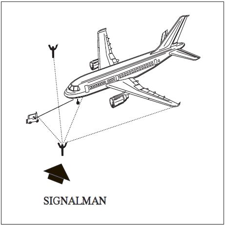
FIG 4-3-12
Signalman's Position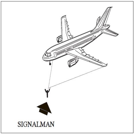
FIG 4-3-13
All Clear (O.K.)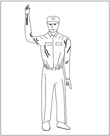
FIG 4-3-14
Start Engine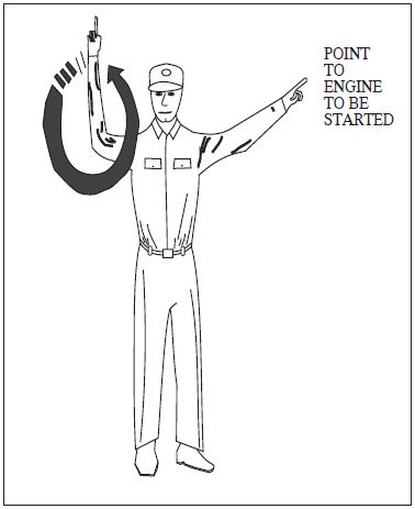
FIG 4-3-15
Pull Chocks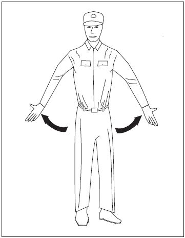
FIG 4-3-16
Proceed Straight Ahead
FIG 4-3-17
Left Turn
FIG 4-3-18
Right Turn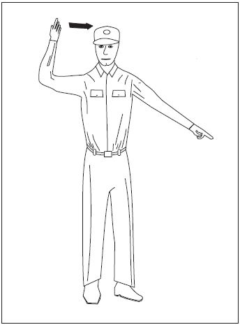
FIG 4-3-19
Slow Down
FIG 4-3-20
Flagman Directs Pilot
FIG 4-3-21
Insert Chocks
FIG 4-3-22
Cut Engines
FIG 4-3-23
Night Operation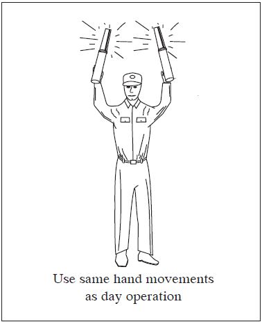
FIG 4-3-24
Stop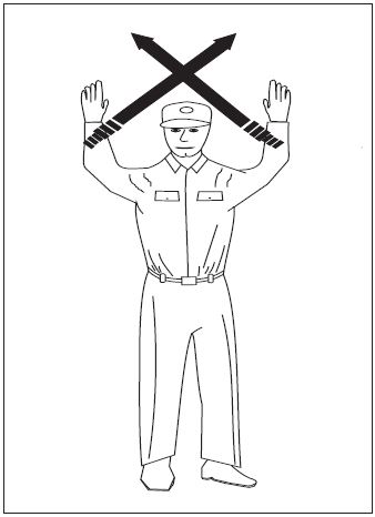
-
Operations at Uncontrolled Airports With Automated Surface Observing System (ASOS)/Automated Weather Observing System (AWOS)
- Many airports throughout the National Airspace System are equipped with either ASOS or AWOS. At most airports with an operating control tower or human observer, the weather will be available to you in an Aviation Routine Weather Report (METAR) hourly or special observation format on the Automatic Terminal Information Service (ATIS) or directly transmitted from the controller/observer.
- At uncontrolled airports that are equipped with ASOS/AWOS with ground-to-air broadcast capability, the one-minute updated airport weather should be available to you within approximately 25 NM of the airport below 10,000 feet. The frequency for the weather broadcast will be published on sectional charts and in the Chart Supplement. Some part-time towered airports may also broadcast the automated weather on their ATIS frequency during the hours that the tower is closed.
-
Controllers issue SVFR or IFR clearances based on pilot request, known traffic and reported weather, i.e., METAR/Nonroutine (Special) Aviation Weather Report (SPECI) observations, when they are available. Pilots have access to more current weather at uncontrolled ASOS/AWOS airports than do the controllers who may be located several miles away. Controllers will rely on the pilot to determine the current airport weather from the ASOS/AWOS. All aircraft arriving or departing an ASOS/AWOS equipped uncontrolled airport should monitor the airport weather frequency to ascertain the status of the airspace. Pilots in Class E airspace must be alert for changing weather conditions which may affect the status of the airspace from IFR/VFR. If ATC service is required for IFR/SVFR approach/departure or requested for VFR service, the pilot should advise the controller that he/she has received the one-minute weather and state his/her intentions.
EXAMPLE-
“I have the (airport) one-minute weather, request an ILS Runway 14 approach.”
REFERENCE-
AIM, Para 7-1-10, Weather Observing Programs.
Section 4. ATC Clearances and Aircraft Separation
-
Clearance
- A clearance issued by ATC is predicated on known traffic and known physical airport conditions. An ATC clearance means an authorization by ATC, for the purpose of preventing collision between known aircraft, for an aircraft to proceed under specified conditions within controlled airspace. IT IS NOT AUTHORIZATION FOR A PILOT TO DEVIATE FROM ANY RULE, REGULATION, OR MINIMUM ALTITUDE NOR TO CONDUCT UNSAFE OPERATION OF THE AIRCRAFT.
- 14 CFR section 91.3(a) states: “The pilot-in-command of an aircraft is directly responsible for, and is the final authority as to, the operation of that aircraft.” If ATC issues a clearance that would cause a pilot to deviate from a rule or regulation, or in the pilot's opinion, would place the aircraft in jeopardy, IT IS THE PILOT'S RESPONSIBILITY TO REQUEST AN AMENDED CLEARANCE. Similarly, if a pilot prefers to follow a different course of action, such as make a 360 degree turn for spacing to follow traffic when established in a landing or approach sequence, land on a different runway, takeoff from a different intersection, takeoff from the threshold instead of an intersection, or delay operation, THE PILOT IS EXPECTED TO INFORM ATC ACCORDINGLY. When the pilot requests a different course of action, however, the pilot is expected to cooperate so as to preclude disruption of traffic flow or creation of conflicting patterns. The pilot is also expected to use the appropriate aircraft call sign to acknowledge all ATC clearances, frequency changes, or advisory information.
-
Each pilot who deviates from an ATC clearance in response to a Traffic Alert and Collision Avoidance System resolution advisory must notify ATC of that deviation as soon as possible.
REFERENCE-
P/CG Term - TRAFFIC ALERT AND COLLISION AVOIDANCE SYSTEM.
- When weather conditions permit, during the time an IFR flight is operating, it is the direct responsibility of the pilot to avoid other aircraft since VFR flights may be operating in the same area without the knowledge of ATC. Traffic clearances provide standard separation only between IFR flights.
-
Clearance Prefix
A clearance, control information, or a response to a request for information originated by an ATC facility and relayed to the pilot through an air-to-ground communication station will be prefixed by “ATC clears,” “ATC advises,” or “ATC requests.”
-
Clearance Items
ATC clearances normally contain the following:
- Clearance Limit. The traffic clearance issued prior to departure will normally authorize flight to the airport of intended landing. Many airports and associated NAVAIDs are collocated with the same name and/or identifier, so care should be exercised to ensure a clear understanding of the clearance limit. When the clearance limit is the airport of intended landing, the clearance should contain the airport name followed by the word “airport.” Under certain conditions, a clearance limit may be a NAVAID or other fix. When the clearance limit is a NAVAID, intersection, or waypoint and the type is known, the clearance should contain type. Under certain conditions, at some locations a short-range clearance procedure is utilized whereby a clearance is issued to a fix within or just outside of the terminal area and pilots are advised of the frequency on which they will receive the long-range clearance direct from the center controller.
-
Departure Procedure. Headings to fly and altitude restrictions may be issued to separate a departure from other air traffic in the terminal area. Where the volume of traffic warrants, DPs have been developed.
REFERENCE-
AIM, Para 5-2-6, Abbreviated IFR Departure Clearance (Cleared. . .as Filed) Procedures.
AIM, Para 5-2-9, Instrument Departure Procedures (DP) - Obstacle Departure Procedures (ODP) and Standard Instrument Departures (SID). -
Route of Flight.
- Clearances are normally issued for the altitude or flight level and route filed by the pilot. However, due to traffic conditions, it is frequently necessary for ATC to specify an altitude or flight level or route different from that requested by the pilot. In addition, flow patterns have been established in certain congested areas or between congested areas whereby traffic capacity is increased by routing all traffic on preferred routes. Information on these flow patterns is available in offices where preflight briefing is furnished or where flight plans are accepted.
- When required, air traffic clearances include data to assist pilots in identifying radio reporting points. It is the responsibility of pilots to notify ATC immediately if their radio equipment cannot receive the type of signals they must utilize to comply with their clearance.
-
Altitude Data.
- The altitude or flight level instructions in an ATC clearance normally require that a pilot “MAINTAIN” the altitude or flight level at which the flight will operate when in controlled airspace. Altitude or flight level changes while en route should be requested prior to the time the change is desired.
- When possible, if the altitude assigned is different from the altitude requested by the pilot, ATC will inform the pilot when to expect climb or descent clearance or to request altitude change from another facility. If this has not been received prior to crossing the boundary of the ATC facility's area and assignment at a different altitude is still desired, the pilot should reinitiate the request with the next facility.
-
The term “cruise” may be used instead of “MAINTAIN” to assign a block of airspace to a pilot from the minimum IFR altitude up to and including the altitude specified in the cruise clearance. The pilot may level off at any intermediate altitude within this block of airspace. Climb/descent within the block is to be made at the discretion of the pilot. However, once the pilot starts descent and verbally reports leaving an altitude in the block, the pilot may not return to that altitude without additional ATC clearance.
REFERENCE-
P/CG Term - CRUISE.
-
Holding Instructions.
- Whenever an aircraft has been cleared to a fix other than the destination airport and delay is expected, it is the responsibility of the ATC controller to issue complete holding instructions (unless the pattern is charted), an EFC time, and a best estimate of any additional en route/terminal delay.
-
If the holding pattern is charted and the controller doesn't issue complete holding instructions, the pilot is expected to hold as depicted on the appropriate chart. When the pattern is charted, the controller may omit all holding instructions except the charted holding direction and the statement AS PUBLISHED, e.g., “HOLD EAST AS PUBLISHED.” Controllers must always issue complete holding instructions when pilots request them.
NOTE-
Only those holding patterns depicted on U.S. government or commercially produced charts which meet FAA requirements should be used.
- If no holding pattern is charted and holding instructions have not been issued, the pilot should ask ATC for holding instructions prior to reaching the fix. This procedure will eliminate the possibility of an aircraft entering a holding pattern other than that desired by ATC. If unable to obtain holding instructions prior to reaching the fix (due to frequency congestion, stuck microphone, etc.), hold in a standard pattern on the course on which you approached the fix and request further clearance as soon as possible. In this event, the altitude/flight level of the aircraft at the clearance limit will be protected so that separation will be provided as required.
- When an aircraft is 3 minutes or less from a clearance limit and a clearance beyond the fix has not been received, the pilot is expected to start a speed reduction so that the aircraft will cross the fix, initially, at or below the maximum holding airspeed.
- When no delay is expected, the controller should issue a clearance beyond the fix as soon as possible and, whenever possible, at least 5 minutes before the aircraft reaches the clearance limit.
-
Pilots should report to ATC the time and altitude/flight level at which the aircraft reaches the clearance limit and report leaving the clearance limit.
NOTE-
In the event of two-way communications failure, pilots are required to comply with 14 CFR section 91.185.
-
Amended Clearances
-
Amendments to the initial clearance will be issued at any time an air traffic controller deems such action necessary to avoid possible confliction between aircraft. Clearances will require that a flight “hold” or change altitude prior to reaching the point where standard separation from other IFR traffic would no longer exist.
NOTE-
Some pilots have questioned this action and requested “traffic information” and were at a loss when the reply indicated “no traffic report.” In such cases the controller has taken action to prevent a traffic confliction which would have occurred at a distant point.
- A pilot may wish an explanation of the handling of the flight at the time of occurrence; however, controllers are not able to take time from their immediate control duties nor can they afford to overload the ATC communications channels to furnish explanations. Pilots may obtain an explanation by directing a letter or telephone call to the chief controller of the facility involved.
- Pilots have the privilege of requesting a different clearance from that which has been issued by ATC if they feel that they have information which would make another course of action more practicable or if aircraft equipment limitations or company procedures forbid compliance with the clearance issued.
-
Amendments to the initial clearance will be issued at any time an air traffic controller deems such action necessary to avoid possible confliction between aircraft. Clearances will require that a flight “hold” or change altitude prior to reaching the point where standard separation from other IFR traffic would no longer exist.
-
Coded Departure Route (CDR)
- CDRs provide air traffic control a rapid means to reroute departing aircraft when the filed route is constrained by either weather or congestion.
- CDRs consist of an eight-character designator that represents a route of flight. The first three alphanumeric characters represent the departure airport, characters four through six represent the arrival airport, and the last two characters are chosen by the overlying ARTCC. For example, PITORDN1 is an alternate route from Pittsburgh to Chicago. Participating aircrews may then be re-cleared by air traffic control via the CDR abbreviated clearance, PITORDN1.
- CDRs are updated on the 56 day charting cycle. Participating aircrews must ensure that their CDR is current.
- Traditionally, CDRs have been used by air transport companies that have signed a Memorandum of Agreement with the local air traffic control facility. General aviation customers who wish to participate in the program may now enter “CDR Capable” in the remarks section of their flight plan.
- When “CDR Capable” is entered into the remarks section of the flight plan the general aviation customer communicates to ATC the ability to decode the current CDR into a flight plan route and the willingness to fly a different route than that which was filed.
-
Special VFR Clearances
-
An ATC clearance must be obtained prior to operating within a Class B, Class C, Class D, or Class E surface area when the weather is less than that required for VFR flight. A VFR pilot may request and be given a clearance to enter, leave, or operate within most Class D and Class E surface areas and some Class B and Class C surface areas in special VFR conditions, traffic permitting, and providing such flight will not delay IFR operations. All special VFR flights must remain clear of clouds. The visibility requirements for special VFR aircraft (other than helicopters) are:
- At least 1 statute mile flight visibility for operations within Class B, Class C, Class D, and Class E surface areas.
- At least 1 statute mile ground visibility if taking off or landing. If ground visibility is not reported at that airport, the flight visibility must be at least 1 statute mile.
- The restrictions in subparagraphs 1 and 2 do not apply to helicopters. Helicopters must remain clear of clouds and may operate in Class B, Class C, Class D, and Class E surface areas with less than 1 statute mile visibility.
- When a control tower is located within the Class B, Class C, or Class D surface area, requests for clearances should be to the tower. In a Class E surface area, a clearance may be obtained from the nearest tower, FSS, or center.
-
It is not necessary to file a complete flight plan with the request for clearance, but pilots should state their intentions in sufficient detail to permit ATC to fit their flight into the traffic flow. The clearance will not contain a specific altitude as the pilot must remain clear of clouds. The controller may require the pilot to fly at or below a certain altitude due to other traffic, but the altitude specified will permit flight at or above the minimum safe altitude. In addition, at radar locations, flights may be vectored if necessary for control purposes or on pilot request.
NOTE-
The pilot is responsible for obstacle or terrain clearance.
REFERENCE-
14 CFR Section 91.119, Minimum safe altitudes: General.
- Special VFR clearances are effective within Class B, Class C, Class D, and Class E surface areas only. ATC does not provide separation after an aircraft leaves the Class B, Class C, Class D, or Class E surface area on a special VFR clearance.
- Special VFR operations by fixed-wing aircraft are prohibited in some Class B and Class C surface areas due to the volume of IFR traffic. A list of these Class B and Class C surface areas is contained in 14 CFR part 91, Appendix D, Section 3. They are also depicted on sectional aeronautical charts.
- ATC provides separation between Special VFR flights and between these flights and other IFR flights.
- Special VFR operations by fixed-wing aircraft are prohibited between sunset and sunrise unless the pilot is instrument rated and the aircraft is equipped for IFR flight.
-
Pilots arriving or departing an uncontrolled airport that has automated weather broadcast capability (ASOS/AWOS) should monitor the broadcast frequency, advise the controller that they have the “one-minute weather” and state intentions prior to operating within the Class B, Class C, Class D, or Class E surface areas.
REFERENCE-
P/CG Term - ONE-MINUTE WEATHER.
-
An ATC clearance must be obtained prior to operating within a Class B, Class C, Class D, or Class E surface area when the weather is less than that required for VFR flight. A VFR pilot may request and be given a clearance to enter, leave, or operate within most Class D and Class E surface areas and some Class B and Class C surface areas in special VFR conditions, traffic permitting, and providing such flight will not delay IFR operations. All special VFR flights must remain clear of clouds. The visibility requirements for special VFR aircraft (other than helicopters) are:
-
Pilot Responsibility upon Clearance Issuance
- Record ATC clearance. When conducting an IFR operation, make a written record of your clearance. The specified conditions which are a part of your air traffic clearance may be somewhat different from those included in your flight plan. Additionally, ATC may find it necessary to ADD conditions, such as particular departure route. The very fact that ATC specifies different or additional conditions means that other aircraft are involved in the traffic situation.
-
ATC Clearance/Instruction Readback. Pilots of airborne aircraft should read back those parts of ATC clearances and instructions containing altitude assignments, vectors, or runway assignments as a means of mutual verification. The read back of the “numbers" serves as a double check between pilots and controllers and reduces the kinds of communications errors that occur when a number is either “misheard" or is incorrect.
-
Include the aircraft identification in all readbacks and acknowledgments. This aids controllers in determining that the correct aircraft received the clearance or instruction. The requirement to include aircraft identification in all readbacks and acknowledgements becomes more important as frequency congestion increases and when aircraft with similar call signs are on the same frequency.
EXAMPLE-
“Climbing to Flight Level three three zero, United Twelve" or “November Five Charlie Tango, roger, cleared to land runway nine left."
- Read back altitudes, altitude restrictions, and vectors in the same sequence as they are given in the clearance or instruction.
- Altitudes contained in charted procedures, such as DPs, instrument approaches, etc., should not be read back unless they are specifically stated by the controller.
- Initial read back of a taxi, departure or landing clearance should include the runway assignment, including left, right, center, etc. if applicable.
-
Include the aircraft identification in all readbacks and acknowledgments. This aids controllers in determining that the correct aircraft received the clearance or instruction. The requirement to include aircraft identification in all readbacks and acknowledgements becomes more important as frequency congestion increases and when aircraft with similar call signs are on the same frequency.
- It is the responsibility of the pilot to accept or refuse the clearance issued.
-
IFR Clearance VFR-on-top
- A pilot on an IFR flight plan operating in VFR weather conditions, may request VFR-on-top in lieu of an assigned altitude. This permits a pilot to select an altitude or flight level of their choice (subject to any ATC restrictions.)
- Pilots desiring to climb through a cloud, haze, smoke, or other meteorological formation and then either cancel their IFR flight plan or operate VFR‐on‐top may request a climb to VFR‐on‐top. The ATC authorization must contain either a top report or a statement that no top report is available, and a request to report reaching VFR‐on‐top. Additionally, the ATC authorization may contain a clearance limit, routing and an alternative clearance if VFR-on-top is not reached by a specified altitude.
- A pilot on an IFR flight plan, operating in VFR conditions, may request to climb/descend in VFR conditions.
- ATC may not authorize VFR-on-top/VFR conditions operations unless the pilot requests the VFR operation or a clearance to operate in VFR conditions will result in noise abatement benefits where part of the IFR departure route does not conform to an FAA approved noise abatement route or altitude.
-
When operating in VFR conditions with an ATC authorization to “maintain VFR-on-top/maintain VFR conditions” pilots on IFR flight plans must:
- Fly at the appropriate VFR altitude as prescribed in 14 CFR section 91.159.
- Comply with the VFR visibility and distance from cloud criteria in 14 CFR section 91.155 (Basic VFR Weather Minimums).
-
Comply with instrument flight rules that are applicable to this flight; i.e., minimum IFR altitudes, position reporting, radio communications, course to be flown, adherence to ATC clearance, etc.
NOTE-
Pilots should advise ATC prior to any altitude change to ensure the exchange of accurate traffic information.
- ATC authorization to “maintain VFR-on-top” is not intended to restrict pilots so that they must operate only above an obscuring meteorological formation (layer). Instead, it permits operation above, below, between layers, or in areas where there is no meteorological obscuration. It is imperative, however, that pilots understand that clearance to operate “VFR-on-top/VFR conditions” does not imply cancellation of the IFR flight plan.
-
Pilots operating VFR-on-top/VFR conditions may receive traffic information from ATC on other pertinent IFR or VFR aircraft. However, aircraft operating in Class B airspace/TRSAs must be separated as required by FAA Order JO 7110.65, Air Traffic Control.
NOTE-
When operating in VFR weather conditions, it is the pilot's responsibility to be vigilant so as to see-and-avoid other aircraft.
-
ATC will not authorize VFR or VFR-on-top operations in Class A airspace.
REFERENCE-
AIM, Para 3-2-2, Class A Airspace.
-
VFR/IFR Flights
A pilot departing VFR, either intending to or needing to obtain an IFR clearance en route, must be aware of the position of the aircraft and the relative terrain/obstructions. When accepting a clearance below the MEA/MIA/MVA/OROCA, pilots are responsible for their own terrain/obstruction clearance until reaching the MEA/MIA/MVA/OROCA. If pilots are unable to maintain terrain/obstruction clearance, the controller should be advised and pilots should state their intentions.
NOTE-
OROCA is a published altitude which provides 1,000 feet of terrain and obstruction clearance in the US (2,000 feet of clearance in designated mountainous areas). These altitudes are not assessed for NAVAID signal coverage, air traffic control surveillance, or communications coverage, and are published for general situational awareness, flight planning and in-flight contingency use.
-
Adherence to Clearance
- When air traffic clearance has been obtained under either visual or instrument flight rules, the pilot-in-command of the aircraft must not deviate from the provisions thereof unless an amended clearance is obtained. When ATC issues a clearance or instruction, pilots are expected to execute its provisions upon receipt. ATC, in certain situations, will include the word “IMMEDIATELY” in a clearance or instruction to impress urgency of an imminent situation and expeditious compliance by the pilot is expected and necessary for safety. The addition of a VFR or other restriction; i.e., climb or descent point or time, crossing altitude, etc., does not authorize a pilot to deviate from the route of flight or any other provision of the ATC clearance.
- When a heading is assigned or a turn is requested by ATC, pilots are expected to promptly initiate the turn, to complete the turn, and maintain the new heading unless issued additional instructions.
- The term “AT PILOT'S DISCRETION” included in the altitude information of an ATC clearance means that ATC has offered the pilot the option to start climb or descent when the pilot wishes, is authorized to conduct the climb or descent at any rate, and to temporarily level off at any intermediate altitude as desired. However, once the aircraft has vacated an altitude, it may not return to that altitude.
-
When ATC has not used the term “AT PILOT'S DISCRETION” nor imposed any climb or descent restrictions, pilots should initiate climb or descent promptly on acknowledgement of the clearance. Descend or climb at an optimum rate consistent with the operating characteristics of the aircraft to 1,000 feet above or below the assigned altitude, and then attempt to descend or climb at a rate of between 500 and 1,500 fpm until the assigned altitude is reached. If at anytime the pilot is unable to climb or descend at a rate of at least 500 feet a minute, advise ATC. If it is necessary to level off at an intermediate altitude during climb or descent, advise ATC, except when leveling off at 10,000 feet MSL on descent, or 2,500 feet above airport elevation (prior to entering a Class C or Class D surface area), when required for speed reduction.
REFERENCE-
14 CFR section 91.117.
NOTE-
Leveling off at 10,000 feet MSL on descent or 2,500 feet above airport elevation (prior to entering a Class C or Class D surface area) to comply with 14 CFR section 91.117 airspeed restrictions is commonplace. Controllers anticipate this action and plan accordingly. Leveling off at any other time on climb or descent may seriously affect air traffic handling by ATC. Consequently, it is imperative that pilots make every effort to fulfill the above expected actions to aid ATC in safely handling and expediting traffic.
-
If the altitude information of an ATC DESCENT clearance includes a provision to “CROSS (fix) AT” or “AT OR ABOVE/BELOW (altitude),” the manner in which the descent is executed to comply with the crossing altitude is at the pilot's discretion. This authorization to descend at pilot's discretion is only applicable to that portion of the flight to which the crossing altitude restriction applies, and the pilot is expected to comply with the crossing altitude as a provision of the clearance. Any other clearance in which pilot execution is optional will so state “AT PILOT'S DISCRETION.”
EXAMPLE-
- “United Four Seventeen, descend and maintain six thousand.”
NOTE-
- The pilot is expected to commence descent upon receipt of the clearance and to descend at the suggested rates until reaching the assigned altitude of 6,000 feet.
EXAMPLE-
- “United Four Seventeen, descend at pilot's discretion, maintain six thousand.”
NOTE-
- The pilot is authorized to conduct descent within the context of the term at pilot's discretion as described above.
EXAMPLE-
- “United Four Seventeen, cross Lakeview V-O-R at or above Flight Level two zero zero, descend and maintain six thousand.”
NOTE-
- The pilot is authorized to conduct descent at pilot's discretion until reaching Lakeview VOR and must comply with the clearance provision to cross the Lakeview VOR at or above FL 200. After passing Lakeview VOR, the pilot is expected to descend at the suggested rates until reaching the assigned altitude of 6,000 feet.
EXAMPLE-
- “United Four Seventeen, cross Lakeview V-O-R at six thousand, maintain six thousand.”
NOTE-
- The pilot is authorized to conduct descent at pilot's discretion, however, must comply with the clearance provision to cross the Lakeview VOR at 6,000 feet.
EXAMPLE-
- “United Four Seventeen, descend now to Flight Level two seven zero, cross Lakeview V-O-R at or below one zero thousand, descend and maintain six thousand.”
NOTE-
- The pilot is expected to promptly execute and complete descent to FL 270 upon receipt of the clearance. After reaching FL 270 the pilot is authorized to descend “at pilot's discretion” until reaching Lakeview VOR. The pilot must comply with the clearance provision to cross Lakeview VOR at or below 10,000 feet. After Lakeview VOR the pilot is expected to descend at the suggested rates until reaching 6,000 feet.
EXAMPLE-
- “United Three Ten, descend now and maintain Flight Level two four zero, pilot's discretion after reaching Flight Level two eight zero.”
NOTE-
- The pilot is expected to commence descent upon receipt of the clearance and to descend at the suggested rates until reaching FL 280. At that point, the pilot is authorized to continue descent to FL 240 within the context of the term “at pilot's discretion” as described above.
- In case emergency authority is used to deviate from provisions of an ATC clearance, the pilot-in-command must notify ATC as soon as possible and obtain an amended clearance. In an emergency situation which does not result in a deviation from the rules prescribed in 14 CFR part 91 but which requires ATC to give priority to an aircraft, the pilot of such aircraft must, when requested by ATC, make a report within 48 hours of such emergency situation to the manager of that ATC facility.
-
The guiding principle is that the last ATC clearance has precedence over the previous ATC clearance. When the route or altitude in a previously issued clearance is amended, the controller will restate applicable altitude restrictions. If altitude to maintain is changed or restated, whether prior to departure or while airborne, and previously issued altitude restrictions are omitted, those altitude restrictions are canceled, including departure procedures and STAR altitude restrictions.
EXAMPLE-
- A departure flight receives a clearance to destination airport to maintain FL 290. The clearance incorporates a DP which has certain altitude crossing restrictions. Shortly after takeoff, the flight receives a new clearance changing the maintaining FL from 290 to 250. If the altitude restrictions are still applicable, the controller restates them.
- A departing aircraft is cleared to cross Fluky Intersection at or above 3,000 feet, Gordonville VOR at or above 12,000 feet, maintain FL 200. Shortly after departure, the altitude to be maintained is changed to FL 240. If the altitude restrictions are still applicable, the controller issues an amended clearance as follows:
“cross Fluky Intersection at or above three thousand, cross Gordonville V-O-R at or above one two thousand, maintain Flight Level two four zero.” - An arriving aircraft is cleared to the destination airport via V45 Delta VOR direct; the aircraft is cleared to cross Delta VOR at 10,000 feet, and then to maintain 6,000 feet. Prior to Delta VOR, the controller issues an amended clearance as follows:
“turn right heading one eight zero for vector to runway three six I-L-S approach, maintain six thousand.”
NOTE-
Because the altitude restriction “cross Delta V-O-R at 10,000 feet” was omitted from the amended clearance, it is no longer in effect.
- Pilots of turbojet aircraft equipped with afterburner engines should advise ATC prior to takeoff if they intend to use afterburning during their climb to the en route altitude. Often, the controller may be able to plan traffic to accommodate a high performance climb and allow the aircraft to climb to the planned altitude without restriction.
- If an “expedite” climb or descent clearance is issued by ATC, and the altitude to maintain is subsequently changed or restated without an expedite instruction, the expedite instruction is canceled. Expedite climb/descent normally indicates to the pilot that the approximate best rate of climb/descent should be used without requiring an exceptional change in aircraft handling characteristics. Normally controllers will inform pilots of the reason for an instruction to expedite.
-
IFR Separation Standards
- ATC effects separation of aircraft vertically by assigning different altitudes; longitudinally by providing an interval expressed in time or distance between aircraft on the same, converging, or crossing courses, and laterally by assigning different flight paths.
- Separation will be provided between all aircraft operating on IFR flight plans except during that part of the flight (outside Class B airspace or a TRSA) being conducted on a VFR-on-top/VFR conditions clearance. Under these conditions, ATC may issue traffic advisories, but it is the sole responsibility of the pilot to be vigilant so as to see and avoid other aircraft.
-
When radar is employed in the separation of aircraft at the same altitude, a minimum of 3 miles separation is provided between aircraft operating within 40 miles of the radar antenna site, and 5 miles between aircraft operating beyond 40 miles from the antenna site. These minima may be increased or decreased in certain specific situations.
NOTE-
Certain separation standards may be increased in the terminal environment due to radar outages or other technical reasons.
-
Speed Adjustments
-
ATC will issue speed adjustments to pilots of radar controlled aircraft to achieve or maintain appropriate spacing. If necessary, ATC will assign a speed when approving deviations or radar vectoring off procedures that include published speed restrictions or a chart note used to transition from Mach to IAS. If no speed is assigned, speed becomes pilot's discretion. However, when the aircraft reaches the end of the STAR, the last published speed on the STAR must be maintained until ATC deletes it, assigns a new speed, issues a vector, assigns a direct route, or issues an approach clearance.
NOTE-
A chart note identifying a speed to maintain after transitioning from Mach to IAS may be published in lieu of or in addition to other published speed restrictions on a STAR.
REFERENCE-
AIM, Para 5-4-1, Standard Terminal Arrival (STAR) Procedures
- ATC will express all speed adjustments in terms of knots based on indicated airspeed (IAS) in 5 or 10 knot increments except that at or above FL 240 speeds may be expressed in terms of Mach numbers in 0.01 increments. The use of Mach numbers is restricted to aircraft with Mach meters.
- Pilots complying with speed adjustments (published or assigned) are expected to maintain a speed within plus or minus 10 knots or 0.02 Mach number of the specified speed.
-
When ATC assigns speed adjustments, it will be in accordance with the following recommended minimums:
-
To aircraft operating between FL 280 and 10,000 feet, a speed not less than 250 knots or the equivalent Mach number.
NOTE-
- On a standard day the Mach numbers equivalent to 250 knots CAS (subject to minor variations) are:
FL 240-0.6
FL 250-0.61
FL 260-0.62
FL 270-0.64
FL 280-0.65
FL 290-0.66. - When an operational advantage will be realized, speeds lower than the recommended minima may be applied.
- On a standard day the Mach numbers equivalent to 250 knots CAS (subject to minor variations) are:
-
To arriving turbojet aircraft operating below 10,000 feet:
- A speed not less than 210 knots, except;
- Within 20 flying miles of the airport of intended landing, a speed not less than 170 knots.
- To arriving reciprocating engine or turboprop aircraft within 20 flying miles of the runway threshold of the airport of intended landing, a speed not less than 150 knots.
-
To departing aircraft:
- Turbojet aircraft, a speed not less than 230 knots.
- Reciprocating engine aircraft, a speed not less than 150 knots.
-
To aircraft operating between FL 280 and 10,000 feet, a speed not less than 250 knots or the equivalent Mach number.
-
When ATC combines a speed adjustment with a descent clearance, the sequence of delivery, with the word “then” between, indicates the expected order of execution.
EXAMPLE-
- Descend and maintain (altitude); then, reduce speed to (speed).
- Reduce speed to (speed); then, descend and maintain (altitude).
NOTE-
The maximum speeds below 10,000 feet as established in 14 CFR section 91.117 still apply. If there is any doubt concerning the manner in which such a clearance is to be executed, request clarification from ATC.
-
If ATC determines (before an approach clearance is issued) that it is no longer necessary to apply speed adjustment procedures, they will:
-
Advise the pilot to “resume normal speed.” Normal speed is used to terminate ATC assigned speed adjustments on segments where no published speed restrictions apply. It does not cancel published restrictions on upcoming procedures. This does not relieve the pilot of those speed restrictions which are applicable to 14 CFR section 91.117.
EXAMPLE-
(An aircraft is flying a SID with no published speed restrictions. ATC issues a speed adjustment and instructs the aircraft where the adjustment ends): “Maintain two two zero knots until BALTR then resume normal speed.”
NOTE-
The ATC assigned speed assignment of two two zero knots would apply until BALTR. The aircraft would then resume a normal operating speed while remaining in compliance with 14 CFR section 91.117.
-
Instruct pilots to “comply with speed restrictions” when the aircraft is joining or resuming a charted procedure or route with published speed restrictions.
EXAMPLE-
(ATC vectors an aircraft off of a SID to rejoin the procedure at a subsequent waypoint. When instructing the aircraft to resume the procedure, ATC also wants the aircraft to comply with the published procedure speed restrictions): “Resume the SALTY ONE departure. Comply with speed restrictions.”
CAUTION-
The phraseology “Descend via/Climb via SID” requires compliance with all altitude and/or speed restrictions depicted on the procedure.
-
Instruct the pilot to “resume published speed.” Resume published speed is issued to terminate a speed adjustment where speed restrictions are published on a charted procedure.
NOTE-
When instructed to “comply with speed restrictions” or to “resume published speed,” ATC anticipates pilots will begin adjusting speed the minimum distance necessary prior to a published speed restriction so as to cross the waypoint/fix at the published speed. Once at the published speed, ATC expects pilots will maintain the published speed until additional adjustment is required to comply with further published or ATC assigned speed restrictions or as required to ensure compliance with 14 CFR section 91.117.
EXAMPLE-
(An aircraft is flying a SID/STAR with published speed restrictions. ATC issues a speed adjustment and instructs the aircraft where the adjustment ends): “Maintain two two zero knots until BALTR then resume published speed.”
NOTE-
The ATC assigned speed assignment of two two zero knots would apply until BALTR. The aircraft would then comply with the published speed restrictions.
-
Advise the pilot to “delete speed restrictions” when either ATC assigned or published speed restrictions on a charted procedure are no longer required.
EXAMPLE-
(An aircraft is flying a SID with published speed restrictions designed to prevent aircraft overtake on departure. ATC determines there is no conflicting traffic and deletes the speed restriction): “Delete speed restrictions.”
NOTE-
When deleting published restrictions, ATC must ensure obstacle clearance until aircraft are established on a route where no published restrictions apply. This does not relieve the pilot of those speed restrictions which are applicable to 14 CFR section 91.117.
-
Instruct the pilot to “climb via” or “descend via.” A climb via or descend via clearance cancels any previously issued speed restrictions and, once established on the depicted departure or arrival, to climb or descend, and to meet all published or assigned altitude and/or speed restrictions.
EXAMPLE-
- (An aircraft is flying a SID with published speed restrictions. ATC has issued a speed restriction of 250 knots for spacing. ATC determines that spacing between aircraft is adequate and desires the aircraft to comply with published restrictions): “United 436, Climb via SID.”
- (An aircraft is established on a STAR. ATC must slow an aircraft for the purposes of spacing and assigns it a speed of 280 knots. When spacing is adequate, ATC deletes the speed restriction and desires that the aircraft comply with all published restrictions on the STAR): “Gulfstream two three papa echo, descend via the TYLER One arrival.”
NOTE-
- In example 1, when ATC issues a “Climb via SID” clearance, it deletes any previously issued speed and/or altitude restrictions. The pilot should then vertically navigate to comply with all speed and/or altitude restrictions published on the SID.
- In example 2, when ATC issues a “Descend via
arrival,” ATC has canceled any previously issued speed and/or altitude restrictions. The pilot should vertically navigate to comply with all speed and/or altitude restrictions published on the STAR.
CAUTION-
When descending on a STAR, pilots should not speed up excessively beyond the previously issued speed. Otherwise, adequate spacing between aircraft descending on the STAR that was established by ATC with the previous restriction may be lost.
-
Advise the pilot to “resume normal speed.” Normal speed is used to terminate ATC assigned speed adjustments on segments where no published speed restrictions apply. It does not cancel published restrictions on upcoming procedures. This does not relieve the pilot of those speed restrictions which are applicable to 14 CFR section 91.117.
- Approach clearances supersede any prior speed adjustment assignments, and pilots are expected to make their own speed adjustments as necessary to complete the approach. However, under certain circumstances, it may be necessary for ATC to issue further speed adjustments after approach clearance is issued to maintain separation between successive arrivals. Under such circumstances, previously issued speed adjustments will be restated if that speed is to be maintained or additional speed adjustments are requested. Speed adjustments should not be assigned inside the final approach fix on final or a point 5 miles from the runway, whichever is closer to the runway.
-
The pilots retain the prerogative of rejecting the application of speed adjustment by ATC if the minimum safe airspeed for any particular operation is greater than the speed adjustment.
NOTE-
In such cases, pilots are expected to advise ATC of the speed that will be used.
- Pilots are reminded that they are responsible for rejecting the application of speed adjustment by ATC if, in their opinion, it will cause them to exceed the maximum indicated airspeed prescribed by 14 CFR section 91.117(a), (c) and (d). IN SUCH CASES, THE PILOT IS EXPECTED TO SO INFORM ATC. Pilots operating at or above 10,000 feet MSL who are issued speed adjustments which exceed 250 knots IAS and are subsequently cleared below 10,000 feet MSL are expected to comply with 14 CFR section 91.117(a).
- Speed restrictions of 250 knots do not apply to U.S. registered aircraft operating beyond 12 nautical miles from the coastline within the U.S. Flight Information Region, in Class E airspace below 10,000 feet MSL. However, in airspace underlying a Class B airspace area designated for an airport, or in a VFR corridor designated through such as a Class B airspace area, pilots are expected to comply with the 200 knot speed limit specified in 14 CFR section 91.117(c).
-
For operations in a Class C and Class D surface area, ATC is authorized to request or approve a speed greater than the maximum indicated airspeeds prescribed for operation within that airspace (14 CFR section 91.117(b)).
NOTE-
Pilots are expected to comply with the maximum speed of 200 knots when operating beneath Class B airspace or in a Class B VFR corridor (14 CFR section 91.117(c) and (d)).
- When in communications with the ARTCC or approach control facility, pilots should, as a good operating practice, state any ATC assigned speed restriction on initial radio contact associated with an ATC communications frequency change.
-
ATC will issue speed adjustments to pilots of radar controlled aircraft to achieve or maintain appropriate spacing. If necessary, ATC will assign a speed when approving deviations or radar vectoring off procedures that include published speed restrictions or a chart note used to transition from Mach to IAS. If no speed is assigned, speed becomes pilot's discretion. However, when the aircraft reaches the end of the STAR, the last published speed on the STAR must be maintained until ATC deletes it, assigns a new speed, issues a vector, assigns a direct route, or issues an approach clearance.
-
Runway Separation
Tower controllers establish the sequence of arriving and departing aircraft by requiring them to adjust flight or ground operation as necessary to achieve proper spacing. They may “HOLD” an aircraft short of the runway to achieve spacing between it and an arriving aircraft; the controller may instruct a pilot to “EXTEND DOWNWIND” in order to establish spacing from an arriving or departing aircraft. At times a clearance may include the word “IMMEDIATE.” For example: “CLEARED FOR IMMEDIATE TAKEOFF.” In such cases “IMMEDIATE” is used for purposes of air traffic separation. It is up to the pilot to refuse the clearance if, in the pilot's opinion, compliance would adversely affect the operation.
REFERENCE-
AIM, Para 4-3-15, Gate Holding due to Departure Delays.
-
Visual Separation
-
Visual separation is a means employed by ATC to separate aircraft in terminal areas and en route airspace in the NAS. There are two methods employed to effect this separation:
- The tower controller sees the aircraft involved and issues instructions, as necessary, to ensure that the aircraft avoid each other.
-
A pilot sees the other aircraft involved and upon instructions from the controller provides separation by maneuvering the aircraft to avoid it. When pilots accept responsibility to maintain visual separation, they must maintain constant visual surveillance and not pass the other aircraft until it is no longer a factor.
NOTE-
Traffic is no longer a factor when during approach phase the other aircraft is in the landing phase of flight or executes a missed approach; and during departure or en route, when the other aircraft turns away or is on a diverging course.
-
A pilot's acceptance of instructions to follow another aircraft or provide visual separation from it is an acknowledgment that the pilot will maneuver the aircraft as necessary to avoid the other aircraft or to maintain in-trail separation. In operations conducted behind heavy aircraft, or a small aircraft behind a B757 or other large aircraft, it is also an acknowledgment that the pilot accepts the responsibility for wake turbulence separation. Visual separation is prohibited behind super aircraft.
NOTE-
When a pilot has been told to follow another aircraft or to provide visual separation from it, the pilot should promptly notify the controller if visual contact with the other aircraft is lost or cannot be maintained or if the pilot cannot accept the responsibility for the separation for any reason.
- Scanning the sky for other aircraft is a key factor in collision avoidance. Pilots and copilots (or the right seat passenger) should continuously scan to cover all areas of the sky visible from the cockpit. Pilots must develop an effective scanning technique which maximizes one's visual capabilities. Spotting a potential collision threat increases directly as more time is spent looking outside the aircraft. One must use timesharing techniques to effectively scan the surrounding airspace while monitoring instruments as well.
- Since the eye can focus only on a narrow viewing area, effective scanning is accomplished with a series of short, regularly spaced eye movements that bring successive areas of the sky into the central visual field. Each movement should not exceed ten degrees, and each area should be observed for at least one second to enable collision detection. Although many pilots seem to prefer the method of horizontal back-and-forth scanning every pilot should develop a scanning pattern that is not only comfortable but assures optimum effectiveness. Pilots should remember, however, that they have a regulatory responsibility (14 CFR section 91.113(a)) to see and avoid other aircraft when weather conditions permit.
-
Visual separation is a means employed by ATC to separate aircraft in terminal areas and en route airspace in the NAS. There are two methods employed to effect this separation:
-
Use of Visual Clearing Procedures and Scanning Techniques
- Before Takeoff. Prior to taxiing onto a runway or landing area in preparation for takeoff, pilots should scan the approach areas for possible landing traffic and execute the appropriate clearing maneuvers to provide them a clear view of the approach areas.
- Climbs and Descents. During climbs and descents in flight conditions which permit visual detection of other traffic, pilots should execute gentle banks, left and right at a frequency which permits continuous visual scanning of the airspace about them.
- Straight and Level. Sustained periods of straight and level flight in conditions which permit visual detection of other traffic should be broken at intervals with appropriate clearing procedures to provide effective visual scanning.
- Traffic Pattern. Entries into traffic patterns while descending create specific collision hazards and should be avoided.
- Traffic at VOR Sites. All operators should emphasize the need for sustained vigilance in the vicinity of VORs and airway intersections due to the convergence of traffic.
-
Training Operations. Operators of pilot training programs are urged to adopt the following practices:
- Pilots undergoing flight instruction at all levels should be requested to verbalize clearing procedures (call out “clear” left, right, above, or below) to instill and sustain the habit of vigilance during maneuvering.
- High-wing airplane. Momentarily raise the wing in the direction of the intended turn and look.
- Low-wing airplane.Momentarily lower the wing in the direction of the intended turn and look.
- Appropriate clearing procedures should precede the execution of all turns including chandelles, lazy eights, stalls, slow flight, climbs, straight and level, spins, and other combination maneuvers.
-
Scanning Techniques for Traffic Avoidance.
-
Pilots must be aware of the limitations inherent in the visual scanning process. These limitations may include:
- Reduced scan frequency due to concentration on flight instruments or tablets and distraction with passengers.
- Blind spots related to high-wing and low-wing aircraft in addition to windshield posts and sun visors.
- Prevailing weather conditions including reduced visibility and the position of the sun.
- The attitude of the aircraft will create additional blind spots.
- The physical limitations of the human eye, including the time required to (re)focus on near and far objects, from the instruments to the horizon for example; empty field myopia, narrow field of vision and atmospheric lighting all affect our ability to detect another aircraft.
-
Best practices to see and avoid:
- ADS-B In is an effective system to help pilots see and avoid other aircraft. If your aircraft is equipped with ADS-B In, it is important to understand its features and how to use it properly. Many units provide visual and/or audio alerts to supplement the system's traffic display. Pilots should incorporate the traffic display in their normal traffic scan to provide awareness of nearby aircraft. Prior to entering or crossing any runway, ADS-B In can provide advance indication of arriving aircraft and aircraft in the traffic pattern. Systems that incorporate a traffic-alerting feature can help minimize the pilot's inclination to fixate on the display. Refer to 4-5-7e, ADS-B Limitations.
- Understand the limitations of ADS-B In. In certain airspace, not all aircraft will be equipped with ADS-B Out or transponders and will not be visible on your ADS-B In display.
- Limit the amount of time that you focus on flight instruments or tablets.
- Develop a strategic approach to scanning for traffic. Scan the entire sky and try not to focus straight ahead.
-
Pilots must be aware of the limitations inherent in the visual scanning process. These limitations may include:
-
Traffic Alert and Collision Avoidance System (TCAS I & II)
- TCAS I provides proximity warning only, to assist the pilot in the visual acquisition of intruder aircraft. No recommended avoidance maneuvers are provided nor authorized as a direct result of a TCAS I warning. It is intended for use by smaller commuter aircraft holding 10 to 30 passenger seats, and general aviation aircraft.
-
TCAS II provides traffic advisories (TA) and resolution advisories (RA). Resolution advisories provide recommended maneuvers in a vertical direction (climb or descend only) to avoid conflicting traffic. Transport category aircraft, and larger commuter and business aircraft holding 31 passenger seats or more, are required to be TCAS II equipped.
- When a TA occurs, attempt to establish visual contact with the traffic but do not deviate from an assigned clearance based only on TA information.
- When an RA occurs, pilots should respond immediately to the RA displays and maneuver as indicated unless doing so would jeopardize the safe operation of the flight, or the flight crew can ensure separation with the help of definitive visual acquisition of the aircraft causing the RA.
- Each pilot who deviates from an ATC clearance in response to an RA must notify ATC of that deviation as soon as practicable, and notify ATC when clear of conflict and returning to their previously assigned clearance.
- Deviations from rules, policies, or clearances should be kept to the minimum necessary to satisfy an RA. Most RA maneuvering requires minimum excursion from assigned altitude.
-
The serving IFR air traffic facility is not responsible to provide approved standard IFR separation to an IFR aircraft, from other aircraft, terrain, or obstructions after an RA maneuver until one of the following conditions exists:
- The aircraft has returned to its assigned altitude and course.
- Alternate ATC instructions have been issued.
-
A crew member informs ATC that the TCAS maneuver has been completed.
NOTE-
TCAS does not alter or diminish the pilot's basic authority and responsibility to ensure safe flight. Since TCAS does not respond to aircraft which are not transponder equipped or aircraft with a transponder failure, TCAS alone does not ensure safe separation in every case. At this time, no air traffic service nor handling is predicated on the availability of TCAS equipment in the aircraft.
-
Traffic Information Service (TIS)
- TIS provides proximity warning only, to assist the pilot in the visual acquisition of intruder aircraft. No recommended avoidance maneuvers are provided nor authorized as a direct result of a TIS intruder display or TIS alert. It is intended for use by aircraft in which TCAS is not required.
- TIS does not alter or diminish the pilot's basic authority and responsibility to ensure safe flight. Since TIS does not respond to aircraft which are not transponder equipped, aircraft with a transponder failure, or aircraft out of radar coverage, TIS alone does not ensure safe separation in every case.
- At this time, no air traffic service nor handling is predicated on the availability of TIS equipment in the aircraft.
- Presently, no air traffic services or handling is predicated on the availability of an ADS-B cockpit display. A “traffic-in-sight” reply to ATC must be based on seeing an aircraft out-the-window, NOT on the cockpit display.
Section 5. Surveillance Systems
-
Radar
-
Capabilities
- Radar is a method whereby radio waves are transmitted into the air and are then received when they have been reflected by an object in the path of the beam. Range is determined by measuring the time it takes (at the speed of light) for the radio wave to go out to the object and then return to the receiving antenna. The direction of a detected object from a radar site is determined by the position of the rotating antenna when the reflected portion of the radio wave is received.
- More reliable maintenance and improved equipment have reduced radar system failures to a negligible factor. Most facilities actually have some components duplicated, one operating and another which immediately takes over when a malfunction occurs to the primary component.
-
Limitations
-
It is very important for the aviation community to recognize the fact that there are limitations to radar service and that ATC controllers may not always be able to issue traffic advisories concerning aircraft which are not under ATC control and cannot be seen on radar. (See FIG 4-5-1.)
FIG 4-5-1
Limitations to Radar Service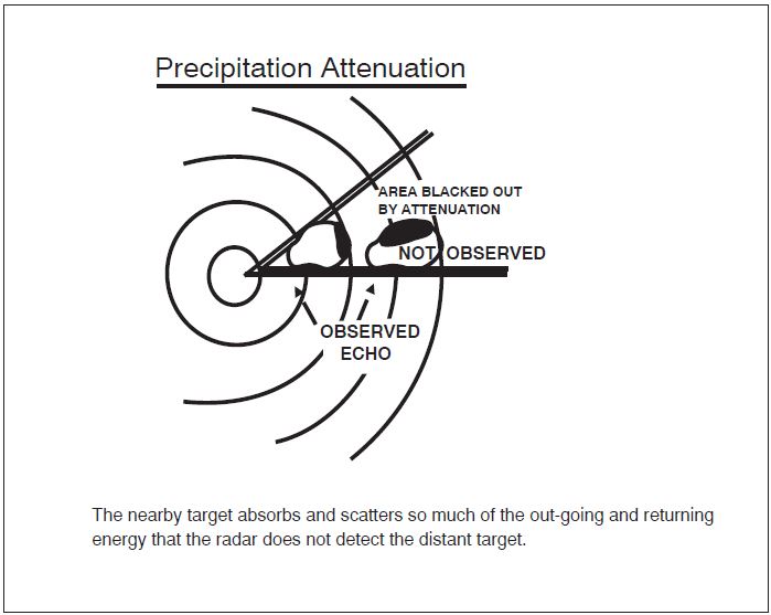
-
The characteristics of radio waves are such that they normally travel in a continuous straight line unless they are:
- “Bent” by abnormal atmospheric phenomena such as temperature inversions;
- Reflected or attenuated by dense objects such as heavy clouds, precipitation, ground obstacles, mountains, etc.; or
- Screened by high terrain features.
- The bending of radar pulses, often called anomalous propagation or ducting, may cause many extraneous blips to appear on the radar operator's display if the beam has been bent toward the ground or may decrease the detection range if the wave is bent upward. It is difficult to solve the effects of anomalous propagation, but using beacon radar and electronically eliminating stationary and slow moving targets by a method called moving target indicator (MTI) usually negate the problem.
- Radar energy that strikes dense objects will be reflected and displayed on the operator's scope thereby blocking out aircraft at the same range and greatly weakening or completely eliminating the display of targets at a greater range. Again, radar beacon and MTI are very effectively used to combat ground clutter and weather phenomena, and a method of circularly polarizing the radar beam will eliminate some weather returns. A negative characteristic of MTI is that an aircraft flying a speed that coincides with the canceling signal of the MTI (tangential or “blind” speed) may not be displayed to the radar controller.
- Relatively low altitude aircraft will not be seen if they are screened by mountains or are below the radar beam due to earth curvature. The historical solution to screening has been the installation of strategically placed multiple radars, which has been done in some areas, but ADS-B now provides ATC surveillance in some areas with challenging terrain where multiple radar installations would be impractical.
- There are several other factors which affect radar control. The amount of reflective surface of an aircraft will determine the size of the radar return. Therefore, a small light airplane or a sleek jet fighter will be more difficult to see on primary radar than a large commercial jet or military bomber. Here again, the use of transponder or ADS-B equipment is invaluable. In addition, all FAA ATC facilities display automatically reported altitude information to the controller from appropriately equipped aircraft.
-
At some locations within the ATC en route environment, secondary-radar-only (no primary radar) gap filler radar systems are used to give lower altitude radar coverage between two larger radar systems, each of which provides both primary and secondary radar coverage. ADS-B serves this same role, supplementing both primary and secondary radar. In those geographical areas served by secondary radar only or ADS-B, aircraft without either transponders or ADS-B equipment cannot be provided with radar service. Additionally, transponder or ADS-B equipped aircraft cannot be provided with radar advisories concerning primary targets and ATC radar-derived weather.
REFERENCE-
P/CG Term - RADAR.
-
With regard to air traffic radar reception, wind turbines generally do not affect the quality of air traffic surveillance radar returns for transponder and ADS-B Out equipped aircraft. Air traffic interference issues apply to the search radar and Non-Transponder/Non-ADS-B Out equipped aircraft.
NOTE-
Generally, one or two wind turbines don't present a significant radar reception loss. A rule of thumb is three (3) or more turbines constitute a wind turbine farm and thus negatively affect the search radar product.
-
Detection loss in the area of a wind turbine farm is substantial. In extreme circumstances, this can extend for more than 1.0 nautical mile (NM) horizontally around the nearest turbine and at all altitudes above the wind turbine farm. (See FIG 4-5-2.)
FIG 4-5-2
Wind Turbine Farm Area of Potential Interference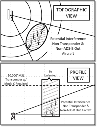
NOTE-
All aircraft should comply with 14 CFR §91.119(c) “…aircraft may not be operated closer than 500 feet to any person, vessel, vehicle, or structure.”
- To avoid interference Non-Transponder/Non-ADS-B Out equipped aircraft should avoid flight within 1.0 NM horizontally, at all altitudes, from the wind turbine farms.
- Because detection loss near and above wind turbine farms for search-only targets causes dropped tracks, erroneous tracks, and can result in loss of separation, it is imperative that Non-Transponder/Non-ADS-B Out equipped aircraft operate at the proper VFR altitudes per hemispheric rule and utilize see-and-avoid techniques.
- Pilots should be aware that air traffic controllers cannot provide separation from Non-Transponder/Non-ADS-B Out equipped aircraft in the vicinity of wind turbine farms. See-and-avoid is the pilot's responsibility, as these non-equipped aircraft may not appear on radar and will not appear on the Traffic Information Services-Broadcast (TIS-B).
-
Detection loss in the area of a wind turbine farm is substantial. In extreme circumstances, this can extend for more than 1.0 nautical mile (NM) horizontally around the nearest turbine and at all altitudes above the wind turbine farm. (See FIG 4-5-2.)
- The controller's ability to advise a pilot flying on instruments or in visual conditions of the aircraft's proximity to another aircraft will be limited if the unknown aircraft is not observed on radar, if no flight plan information is available, or if the volume of traffic and workload prevent issuing traffic information. The controller's first priority is given to establishing vertical, lateral, or longitudinal separation between aircraft flying IFR under the control of ATC.
-
The characteristics of radio waves are such that they normally travel in a continuous straight line unless they are:
-
It is very important for the aviation community to recognize the fact that there are limitations to radar service and that ATC controllers may not always be able to issue traffic advisories concerning aircraft which are not under ATC control and cannot be seen on radar. (See FIG 4-5-1.)
- FAA radar units operate continuously at the locations shown in the Chart Supplement, and their services are available to all pilots, both civil and military. Contact the associated FAA control tower or ARTCC on any frequency guarded for initial instructions, or in an emergency, any FAA facility for information on the nearest radar service.
-
Capabilities
-
Air Traffic Control Radar Beacon System (ATCRBS)
-
The ATCRBS, sometimes referred to as secondary surveillance radar, consists of three main components:
- Interrogator. Primary radar relies on a signal being transmitted from the radar antenna site and for this signal to be reflected or “bounced back” from an object (such as an aircraft). This reflected signal is then displayed as a “target” on the controller's radarscope. In the ATCRBS, the Interrogator, a ground based radar beacon transmitter-receiver, scans in synchronism with the primary radar and transmits discrete radio signals which repetitiously request all transponders, on the mode being used, to reply. The replies received are then mixed with the primary returns and both are displayed on the same radarscope.
- Transponder. This airborne radar beacon transmitter-receiver automatically receives the signals from the interrogator and selectively replies with a specific pulse group (code) only to those interrogations being received on the mode to which it is set. These replies are independent of, and much stronger than a primary radar return.
- Radarscope. The radarscope used by the controller displays returns from both the primary radar system and the ATCRBS. These returns, called targets, are what the controller refers to in the control and separation of traffic.
-
The job of identifying and maintaining identification of primary radar targets is a long and tedious task for the controller. Some of the advantages of ATCRBS over primary radar are:
- Reinforcement of radar targets.
- Rapid target identification.
- Unique display of selected codes.
- A part of the ATCRBS ground equipment is the decoder. This equipment enables a controller to assign discrete transponder codes to each aircraft under his/her control. Normally only one code will be assigned for the entire flight. Assignments are made by the ARTCC computer on the basis of the National Beacon Code Allocation Plan. The equipment is also designed to receive Mode C altitude information from the aircraft.
-
It should be emphasized that aircraft transponders greatly improve the effectiveness of radar systems.
REFERENCE-
AIM, Para 4-1-20, Transponder and ADS-B Out Operation.
-
The ATCRBS, sometimes referred to as secondary surveillance radar, consists of three main components:
-
Surveillance Radar
-
Surveillance radars are divided into two general categories: Airport Surveillance Radar (ASR) and Air Route Surveillance Radar (ARSR).
- ASR is designed to provide relatively short-range coverage in the general vicinity of an airport and to serve as an expeditious means of handling terminal area traffic through observation of precise aircraft locations on a radarscope. The ASR can also be used as an instrument approach aid.
- ARSR is a long-range radar system designed primarily to provide a display of aircraft locations over large areas.
- Surveillance radars scan through 360 degrees of azimuth and present target information on a radar display located in a tower or center. This information is used independently or in conjunction with other navigational aids in the control of air traffic.
-
Surveillance radars are divided into two general categories: Airport Surveillance Radar (ASR) and Air Route Surveillance Radar (ARSR).
-
Precision Approach Radar (PAR)
- PAR is designed for use as a landing aid rather than an aid for sequencing and spacing aircraft. PAR equipment may be used as a primary landing aid (See Chapter 5, Air Traffic Procedures, for additional information), or it may be used to monitor other types of approaches. It is designed to display range, azimuth, and elevation information.
- Two antennas are used in the PAR array, one scanning a vertical plane, and the other scanning horizontally. Since the range is limited to 10 miles, azimuth to 20 degrees, and elevation to 7 degrees, only the final approach area is covered. Each scope is divided into two parts. The upper half presents altitude and distance information, and the lower half presents azimuth and distance.
-
Airport Surface Detection Equipment (ASDE-X)/Airport Surface Surveillance Capability (ASSC)
-
ASDE-X/ASSC is a multi-sensor surface surveillance system the FAA has acquired for airports in the United States. This system provides high resolution, short-range, clutter free surveillance information about aircraft and vehicles, both moving and fixed, located on or near the surface of the airport's runways and taxiways under all weather and visibility conditions. The system consists of:
- A Primary Radar System. ASDE-X/ASSC system coverage includes the airport surface and the airspace up to 200 feet above the surface. Typically located on the control tower or other strategic location on the airport, the Primary Radar antenna is able to detect and display aircraft that are not equipped with or have malfunctioning transponders or ADS-B.
- Interfaces. ASDE-X/ASSC contains an automation interface for flight identification via all automation platforms and interfaces with the terminal radar for position information.
- Automation. A Multi-sensor Data Processor (MSDP) combines all sensor reports into a single target which is displayed to the air traffic controller.
- Air Traffic Control Tower Display. A high resolution, color monitor in the control tower cab provides controllers with a seamless picture of airport operations on the airport surface.
- The combination of data collected from the multiple sensors ensures that the most accurate information about aircraft location is received in the tower, thereby increasing surface safety and efficiency.
-
The following facilities are operational with ASDE-X:
TBL 4-5-1
BWI
Baltimore Washington International
BOS
Boston Logan International
BDL
Bradley International
MDW
Chicago Midway
ORD
Chicago O'Hare International
CLT
Charlotte Douglas International
DFW
Dallas/Fort Worth International
DEN
Denver International
DTW
Detroit Metro Wayne County
FLL
Fort Lauderdale/Hollywood Intl
MKE
General Mitchell International
IAH
George Bush International
ATL
Hartsfield-Jackson Atlanta Intl
HNL
Honolulu International
JFK
John F. Kennedy International
SNA
John Wayne-Orange County
LGA
LaGuardia
STL
Lambert St. Louis International
LAS
Las Vegas Harry Reid International
LAX
Los Angeles International
SDF
Louisville International
MEM
Memphis International
MIA
Miami International
MSP
Minneapolis St. Paul International
EWR
Newark International
MCO
Orlando International
PHL
Philadelphia International
PHX
Phoenix Sky Harbor International
DCA
Ronald Reagan Washington National
SAN
San Diego International
SLC
Salt Lake City International
SEA
Seattle-Tacoma International
PVD
Theodore Francis Green State
IAD
Washington Dulles International
HOU
William P. Hobby International
-
The following facilities have been projected to receive ASSC:
TBL 4-5-2
SFO
San Francisco International
CLE
Cleveland-Hopkins International
MCI
Kansas City International
CVG
Cincinnati/Northern Kentucky Intl
PDX
Portland International
MSY
Louis Armstrong New Orleans Intl
PIT
Pittsburgh International
ANC
Ted Stevens Anchorage International
ADW
Joint Base Andrews AFB
-
ASDE-X/ASSC is a multi-sensor surface surveillance system the FAA has acquired for airports in the United States. This system provides high resolution, short-range, clutter free surveillance information about aircraft and vehicles, both moving and fixed, located on or near the surface of the airport's runways and taxiways under all weather and visibility conditions. The system consists of:
-
Traffic Information Service (TIS)
- Introduction. The Traffic Information Service (TIS) provides information to the cockpit via data link, that is similar to VFR radar traffic advisories normally received over voice radio. Among the first FAA-provided data services, TIS is intended to improve the safety and efficiency of “see and avoid” flight through an automatic display that informs the pilot of nearby traffic and potential conflict situations. This traffic display is intended to assist the pilot in visual acquisition of these aircraft. TIS employs an enhanced capability of the terminal Mode S radar system, which contains the surveillance data, as well as the data link required to “uplink” this information to suitably-equipped aircraft (known as a TIS “client”). TIS provides estimated position, altitude, altitude trend, and ground track information for up to 8 intruder aircraft within 7 NM horizontally, +3,500 and -3,000 feet vertically of the client aircraft (see FIG 4-5-3, TIS Proximity Coverage Volume). The range of a target reported at a distance greater than 7 NM only indicates that this target will be a threat within 34 seconds and does not display a precise distance. TIS will alert the pilot to aircraft (under surveillance of the Mode S radar) that are estimated to be within 34 seconds of potential collision, regardless of distance or altitude. TIS surveillance data is derived from the same radar used by ATC; this data is uplinked to the client aircraft on each radar scan (nominally every 5 seconds).
-
Requirements.
-
In order to use TIS, the client and any intruder aircraft must be equipped with the appropriate cockpit equipment and fly within the radar coverage of a Mode S radar capable of providing TIS. Typically, this will be within 55 NM of the sites depicted in FIG 4-5-4, Terminal Mode S Radar Sites. ATC communication is not a requirement to receive TIS, although it may be required by the particular airspace or flight operations in which TIS is being used.
FIG 4-5-3
TIS Proximity Coverage Volume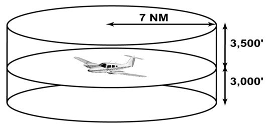
FIG 4-5-4
Terminal Mode S Radar Sites
FIG 4-5-5
Traffic Information Service (TIS) Avionics Block Diagram
-
The cockpit equipment functionality required by a TIS client aircraft to receive the service consists of the following (refer to FIG 4-5-5):
- Mode S data link transponder with altitude encoder.
- Data link applications processor with TIS software installed.
- Control-display unit.
-
Optional equipment includes a digital heading source to correct display errors caused by “crab angle” and turning maneuvers.
NOTE-
Some of the above functions will likely be combined into single pieces of avionics, such as (a) and (b).
- To be visible to the TIS client, the intruder aircraft must, at a minimum, have an operating transponder (Mode A, C or S). All altitude information provided by TIS from intruder aircraft is derived from Mode C reports, if appropriately equipped.
-
TIS will initially be provided by the terminal Mode S systems that are paired with ASR-9 digital primary radars. These systems are in locations with the greatest traffic densities, thus will provide the greatest initial benefit. The remaining terminal Mode S sensors, which are paired with ASR-7 or ASR-8 analog primary radars, will provide TIS pending modification or relocation of these sites. See FIG 4-5-4, Terminal Mode S Radar Sites, for site locations. There is no mechanism in place, such as NOTAMs, to provide status update on individual radar sites since TIS is a nonessential, supplemental information service.
The FAA also operates en route Mode S radars (not illustrated) that rotate once every 12 seconds. These sites will require additional development of TIS before any possible implementation. There are no plans to implement TIS in the en route Mode S radars at the present time.
-
In order to use TIS, the client and any intruder aircraft must be equipped with the appropriate cockpit equipment and fly within the radar coverage of a Mode S radar capable of providing TIS. Typically, this will be within 55 NM of the sites depicted in FIG 4-5-4, Terminal Mode S Radar Sites. ATC communication is not a requirement to receive TIS, although it may be required by the particular airspace or flight operations in which TIS is being used.
-
Capabilities.
- TIS provides ground-based surveillance information over the Mode S data link to properly equipped client aircraft to aid in visual acquisition of proximate air traffic. The actual avionics capability of each installation will vary and the supplemental handbook material must be consulted prior to using TIS. A maximum of eight (8) intruder aircraft may be displayed; if more than eight aircraft match intruder parameters, the eight “most significant” intruders are uplinked. These “most significant” intruders are usually the ones in closest proximity and/or the greatest threat to the TIS client.
-
TIS, through the Mode S ground sensor, provides the following data on each intruder aircraft:
- Relative bearing information in 6-degree increments.
- Relative range information in 1/8 NM to 1 NM increments (depending on range).
- Relative altitude in 100-foot increments (within 1,000 feet) or 500-foot increments (from 1,000-3,500 feet) if the intruder aircraft has operating altitude reporting capability.
- Estimated intruder ground track in 45-degree increments.
- Altitude trend data (level within 500 fpm or climbing/descending >500 fpm) if the intruder aircraft has operating altitude reporting capability.
- Intruder priority as either an “traffic advisory” or “proximate” intruder.
- When flying from surveillance coverage of one Mode S sensor to another, the transfer of TIS is an automatic function of the avionics system and requires no action from the pilot.
-
There are a variety of status messages that are provided by either the airborne system or ground equipment to alert the pilot of high priority intruders and data link system status. These messages include the following:
- Alert. Identifies a potential collision hazard within 34 seconds. This alert may be visual and/or audible, such as a flashing display symbol or a headset tone. A target is a threat if the time to the closest approach in vertical and horizontal coordinates is less than 30 seconds and the closest approach is expected to be within 500 feet vertically and 0.5 nautical miles laterally.
- TIS Traffic. TIS traffic data is displayed.
- Coasting. The TIS display is more than 6 seconds old. This indicates a missing uplink from the ground system. When the TIS display information is more than 12 seconds old, the “No Traffic” status will be indicated.
- No Traffic. No intruders meet proximate or alert criteria. This condition may exist when the TIS system is fully functional or may indicate “coasting” between 12 and 59 seconds old (see (c) above).
- TIS Unavailable. The pilot has requested TIS, but no ground system is available. This condition will also be displayed when TIS uplinks are missing for 60 seconds or more.
- TIS Disabled. The pilot has not requested TIS or has disconnected from TIS.
-
Good-bye. The client aircraft has flown outside of TIS coverage.
NOTE-
Depending on the avionics manufacturer implementation, it is possible that some of these messages will not be directly available to the pilot.
- Depending on avionics system design, TIS may be presented to the pilot in a variety of different displays, including text and/or graphics. Voice annunciation may also be used, either alone or in combination with a visual display. FIG 4-5-5, Traffic Information Service (TIS), Avionics Block Diagram, shows an example of a TIS display using symbology similar to the Traffic Alert and Collision Avoidance System (TCAS) installed on most passenger air carrier/commuter aircraft in the U.S. The small symbol in the center represents the client aircraft and the display is oriented “track up,” with the 12 o'clock position at the top. The range rings indicate 2 and 5 NM. Each intruder is depicted by a symbol positioned at the approximate relative bearing and range from the client aircraft. The circular symbol near the center indicates an “alert” intruder and the diamond symbols indicate “proximate” intruders.
-
The inset in the lower right corner of FIG 4-5-5, Traffic Information Service (TIS), Avionics Block Diagram, shows a possible TIS data block display. The following information is contained in this data block:
- The intruder, located approximately four o'clock, three miles, is a “proximate” aircraft and currently not a collision threat to the client aircraft. This is indicated by the diamond symbol used in this example.
- The intruder ground track diverges to the right of the client aircraft, indicated by the small arrow.
- The intruder altitude is 700 feet less than or below the client aircraft, indicated by the “-07” located under the symbol.
-
The intruder is descending >500 fpm, indicated by the downward arrow next to the “-07” relative altitude information. The absence of this arrow when an altitude tag is present indicates level flight or a climb/descent rate less than 500 fpm.
NOTE-
If the intruder did not have an operating altitude encoder (Mode C), the altitude and altitude trend “tags” would have been omitted.
-
Limitations.
- TIS is NOT intended to be used as a collision avoidance system and does not relieve the pilot's responsibility to “see and avoid” other aircraft (see paragraph 5-5-8, See and Avoid). TIS must not be used for avoidance maneuvers during IMC or other times when there is no visual contact with the intruder aircraft. TIS is intended only to assist in visual acquisition of other aircraft in VMC. Avoidance maneuvers are neither provided nor authorized as a direct result of a TIS intruder display or TIS alert.
-
While TIS is a useful aid to visual traffic avoidance, it has some system limitations that must be fully understood to ensure proper use. Many of these limitations are inherent in secondary radar surveillance. In other words, the information provided by TIS will be no better than that provided to ATC. Other limitations and anomalies are associated with the TIS predictive algorithm.
- Intruder Display Limitations. TIS will only display aircraft with operating transponders installed. TIS relies on surveillance of the Mode S radar, which is a “secondary surveillance” radar similar to the ATCRBS described in paragraph 4-5-2.
- TIS Client Altitude Reporting Requirement. Altitude reporting is required by the TIS client aircraft in order to receive TIS. If the altitude encoder is inoperative or disabled, TIS will be unavailable, as TIS requests will not be honored by the ground system. As such, TIS requires altitude reporting to determine the Proximity Coverage Volume as indicated in FIG 4-5-3. TIS users must be alert to altitude encoder malfunctions, as TIS has no mechanism to determine if client altitude reporting is correct. A failure of this nature will cause erroneous and possibly unpredictable TIS operation. If this malfunction is suspected, confirmation of altitude reporting with ATC is suggested.
- Intruder Altitude Reporting. Intruders without altitude reporting capability will be displayed without the accompanying altitude tag. Additionally, nonaltitude reporting intruders are assumed to be at the same altitude as the TIS client for alert computations. This helps to ensure that the pilot will be alerted to all traffic under radar coverage, but the actual altitude difference may be substantial. Therefore, visual acquisition may be difficult in this instance.
-
Coverage Limitations. Since TIS is provided by ground-based, secondary surveillance radar, it is subject to all limitations of that radar. If an aircraft is not detected by the radar, it cannot be displayed on TIS. Examples of these limitations are as follows:
- TIS will typically be provided within 55 NM of the radars depicted in FIG 4-5-4, Terminal Mode S Radar Sites. This maximum range can vary by radar site and is always subject to “line of sight” limitations; the radar and data link signals will be blocked by obstructions, terrain, and curvature of the earth.
- TIS will be unavailable at low altitudes in many areas of the country, particularly in mountainous regions. Also, when flying near the “floor” of radar coverage in a particular area, intruders below the client aircraft may not be detected by TIS.
- TIS will be temporarily disrupted when flying directly over the radar site providing coverage if no adjacent site assumes the service. A ground-based radar, similar to a VOR or NDB, has a zenith cone, sometimes referred to as the cone of confusion or cone of silence. This is the area of ambiguity directly above the station where bearing information is unreliable. The zenith cone setting for TIS is 34 degrees: Any aircraft above that angle with respect to the radar horizon will lose TIS coverage from that radar until it is below this 34 degree angle. The aircraft may not actually lose service in areas of multiple radar coverage since an adjacent radar will provide TIS. If no other TIS-capable radar is available, the “Good-bye” message will be received and TIS terminated until coverage is resumed.
- Intermittent Operations. TIS operation may be intermittent during turns or other maneuvering, particularly if the transponder system does not include antenna diversity (antenna mounted on the top and bottom of the aircraft). As in (d) above, TIS is dependent on two-way, “line of sight” communications between the aircraft and the Mode S radar. Whenever the structure of the client aircraft comes between the transponder antenna (usually located on the underside of the aircraft) and the ground-based radar antenna, the signal may be temporarily interrupted.
-
TIS Predictive Algorithm. TIS information is collected one radar scan prior to the scan during which the uplink occurs. Therefore, the surveillance information is approximately 5 seconds old. In order to present the intruders in a “real time” position, TIS uses a “predictive algorithm” in its tracking software. This algorithm uses track history data to extrapolate intruders to their expected positions consistent with the time of display in the cockpit. Occasionally, aircraft maneuvering will cause this algorithm to induce errors in the TIS display. These errors primarily affect relative bearing information; intruder distance and altitude will remain relatively accurate and may be used to assist in “see and avoid.” Some of the more common examples of these errors are as follows:
- When client or intruder aircraft maneuver excessively or abruptly, the tracking algorithm will report incorrect horizontal position until the maneuvering aircraft stabilizes.
-
When a rapidly closing intruder is on a course that crosses the client at a shallow angle (either overtaking or head on) and either aircraft abruptly changes course within ¼ NM, TIS will display the intruder on the opposite side of the client than it actually is.
These are relatively rare occurrences and will be corrected in a few radar scans once the course has stabilized.
- Heading/Course Reference. Not all TIS aircraft installations will have onboard heading reference information. In these installations, aircraft course reference to the TIS display is provided by the Mode S radar. The radar only determines ground track information and has no indication of the client aircraft heading. In these installations, all intruder bearing information is referenced to ground track and does not account for wind correction. Additionally, since ground-based radar will require several scans to determine aircraft course following a course change, a lag in TIS display orientation (intruder aircraft bearing) will occur. As in (f) above, intruder distance and altitude are still usable.
-
Closely-Spaced Intruder Errors. When operating more than 30 NM from the Mode S sensor, TIS forces any intruder within 3/8 NM of the TIS client to appear at the same horizontal position as the client aircraft. Without this feature, TIS could display intruders in a manner confusing to the pilot in critical situations (for example, a closely-spaced intruder that is actually to the right of the client may appear on the TIS display to the left). At longer distances from the radar, TIS cannot accurately determine relative bearing/distance information on intruder aircraft that are in close proximity to the client.
Because TIS uses a ground-based, rotating radar for surveillance information, the accuracy of TIS data is dependent on the distance from the sensor (radar) providing the service. This is much the same phenomenon as experienced with ground-based navigational aids, such as a VOR. As distance from the radar increases, the accuracy of surveillance decreases. Since TIS does not inform the pilot of distance from the Mode S radar, the pilot must assume that any intruder appearing at the same position as the client aircraft may actually be up to 3/8 NM away in any direction. Consistent with the operation of TIS, an alert on the display (regardless of distance from the radar) should stimulate an outside visual scan, intruder acquisition, and traffic avoidance based on outside reference.
-
Reports of TIS Malfunctions.
-
Users of TIS can render valuable assistance in the early correction of malfunctions by reporting their observations of undesirable performance. Reporters should identify the time of observation, location, type and identity of aircraft, and describe the condition observed; the type of transponder processor, and software in use can also be useful information. Since TIS performance is monitored by maintenance personnel rather than ATC, it is suggested that malfunctions be reported by radio or telephone to the nearest Flight Service Station (FSS) facility.
NOTE-
TIS operates at only those terminal Mode S radar sites depicted in FIG 4-5-4. Though similar in some ways, TIS is not related to TIS-B (Traffic Information Service-Broadcast).
-
Users of TIS can render valuable assistance in the early correction of malfunctions by reporting their observations of undesirable performance. Reporters should identify the time of observation, location, type and identity of aircraft, and describe the condition observed; the type of transponder processor, and software in use can also be useful information. Since TIS performance is monitored by maintenance personnel rather than ATC, it is suggested that malfunctions be reported by radio or telephone to the nearest Flight Service Station (FSS) facility.
-
Automatic Dependent Surveillance-Broadcast (ADS-B) Services
-
Introduction.
- Automatic Dependent Surveillance-Broadcast (ADS-B) is a surveillance technology deployed throughout the NAS (see FIG 4-5-6). The ADS-B system is composed of aircraft avionics and a ground infrastructure. Onboard avionics determine the position of the aircraft by using the GNSS and transmit its position along with additional information about the aircraft to ground stations for use by ATC and other ADS-B services. This information is transmitted at a rate of approximately once per second. (See FIG 4-5-7 and FIG 4-5-8.)
- In the United States, ADS-B equipped aircraft exchange information on one of two frequencies: 978 or 1090 MHz. The 1090 MHz frequency is also associated with Mode A, C, and S transponder operations. 1090 MHz transponders with integrated ADS-B functionality extend the transponder message sets with additional ADS-B information. This additional information is known as an “extended squitter” message and is referred to as 1090ES. ADS-B equipment operating on 978 MHz is known as the Universal Access Transceiver (UAT).
- ADS-B avionics can have the ability to both transmit and receive information. The transmission of ADS-B information from an aircraft is known as ADS-B Out. The receipt of ADS-B information by an aircraft is known as ADS-B In. All aircraft operating within the airspace defined in 14 CFR § 91.225 are required to transmit the information defined in § 91.227 using ADS-B Out avionics.
-
In general, operators flying at 18,000 feet and above (Class A airspace) are required to have 1090ES equipment. Those that do not fly above 18,000 may use either UAT or 1090ES equipment. (Refer to 14 CFR §§ 91.225 and 91.227.) While the regulations do not require it, operators equipped with ADS-B In will realize additional benefits from ADS-B broadcast services: Traffic Information Service - Broadcast (TIS-B) (paragraph 4-5-8) and Flight Information Service - Broadcast (FIS-B) (paragraph 4-5-9).
FIG 4-5-6
ADS-B, TIS-B, and FIS-B: Broadcast Services Architecture
-
ADS-B Certification and Performance Requirements.
ADS-B equipment may be certified as a surveillance source for air traffic separation services using ADS-B Out. ADS-B equipment may also be certified for use with ADS-B In advisory services that enable appropriately equipped aircraft to display traffic and flight information. Refer to the aircraft's flight manual supplement or Pilot Operating Handbook for the capabilities of a specific aircraft installation. -
ADS-B Capabilities and Procedures.
-
ADS-B enables improved surveillance services, both air-to-air and air-to-ground, especially in areas where radar is ineffective due to terrain or where it is impractical or cost prohibitive. Initial NAS applications of air-to-air ADS-B are for “advisory” use only, enhancing a pilot's visual acquisition of other nearby equipped aircraft either when airborne or on the airport surface. Additionally, ADS-B will enable ATC and fleet operators to monitor aircraft throughout the available ground station coverage area.
FIG 4-5-7
En Route - ADS-B/ADS-R/TIS-B/FIS-B Service Ceilings/Floors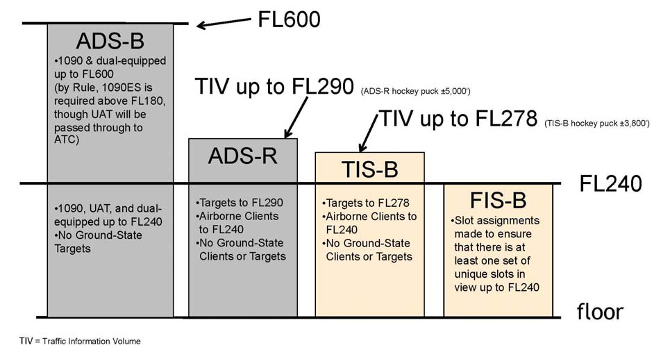
FIG 4-5-8
Terminal - ADS-B/ADS-R/TIS-B/FIS-B Service Ceilings/Floors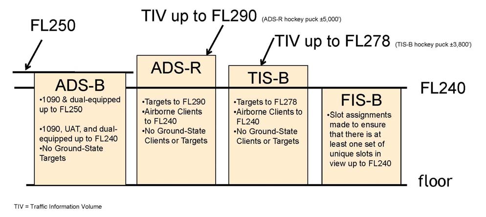
-
One of the data elements transmitted by ADS-B is the aircraft's Flight Identification (FLT ID). The FLT ID is comprised of a maximum of seven alphanumeric characters and must correspond to the aircraft identification filed in the flight plan. For airline and commuter aircraft, the FLT ID is usually the company name and flight number (for example, AAL3432), and is typically entered into the avionics by the flight crew during preflight. For general aviation (GA), if aircraft avionics allow dynamic modification of the FLT ID, the pilot can enter it prior to flight. However, some ADS-B avionics require the FLT ID to be set to the aircraft registration number (for example, N1234Q) by the installer and cannot be changed by the pilot from the cockpit. In both cases, the FLT ID must correspond to the aircraft identification filed in its flight plan.
ATC automation systems use the transmitted ADS-B FLT ID to uniquely identify each aircraft within a given airspace, and to correlate it to its filed flight plan for the purpose of providing surveillance and separation services. If the FLT ID and the filed aircraft identification are not identical, a Call Sign Mis-Match (CSMM) is generated and ATC automation systems may not associate the aircraft with its filed flight plan. In this case, air traffic services may be delayed or unavailable until the CSMM is corrected. Consequently, it is imperative that flight crews and GA pilots ensure the FLT ID entry correctly matches the aircraft identification filed in their flight plan. - Each ADS-B aircraft is assigned a unique ICAO address (also known as a 24-bit address) that is broadcast by the ADS-B transmitter. This ICAO address is programmed at installation. Should multiple aircraft broadcast the same ICAO address while transiting the same ADS-B Only Service Volume, the ADS-B network may be unable to track the targets correctly. If radar reinforcement is available, tracking will continue. If radar is unavailable, the controller may lose target tracking entirely on one or both targets. Consequently, it is imperative that the ICAO address entry is correct.
- Aircraft that are equipped with ADS-B avionics on the UAT datalink have a feature that allows them to broadcast an anonymous 24-bit ICAO address. In this mode, the UAT system creates a randomized address that does not match the actual ICAO address assigned to the aircraft. The UAT anonymous 24-bit address feature may only be used when the operator has not filed an IFR flight plan and is not requesting ATC services. In the anonymity mode, the aircraft's beacon code must be set to 1200 and, depending on the manufacturer's implementation, the aircraft FLT ID might not be transmitted. Pilots should be aware that while in UAT anonymity mode, they will not be eligible to receive ATC separation and flight following services, and may not benefit from enhanced ADS-B search and rescue capabilities.
- ADS-B systems integrated with the transponder will automatically set the applicable emergency status when 7500, 7600, or 7700 are entered into the transponder. ADS-B systems not integrated with the transponder, or systems with optional emergency codes, will require that the appropriate emergency code is entered through a pilot interface. ADS-B is intended for inflight and airport surface use. Unless otherwise directed by ATC, transponder/ADS-B systems should be turned “on” and remain “on” whenever operating in the air or on the airport surface movement area.
-
ADS-B enables improved surveillance services, both air-to-air and air-to-ground, especially in areas where radar is ineffective due to terrain or where it is impractical or cost prohibitive. Initial NAS applications of air-to-air ADS-B are for “advisory” use only, enhancing a pilot's visual acquisition of other nearby equipped aircraft either when airborne or on the airport surface. Additionally, ADS-B will enable ATC and fleet operators to monitor aircraft throughout the available ground station coverage area.
-
ATC Surveillance Services using ADS-B - Procedures and Recommended Phraseology
Radar procedures, with the exceptions found in this paragraph, are identical to those procedures prescribed for radar in AIM Chapter 4 and Chapter 5.-
Preflight:
If ATC services are anticipated when either a VFR or IFR flight plan is filed, the aircraft identification (as entered in the flight plan) must be entered as the FLT ID in the ADS-B avionics. -
Inflight:
When requesting surveillance services while airborne, pilots must disable the anonymous feature, if so equipped, prior to contacting ATC. Pilots must also ensure that their transmitted ADS-B FLT ID matches the aircraft identification as entered in their flight plan. -
Aircraft with an Inoperative/Malfunctioning ADS-B Transmitter:
-
ATC will inform the flight crew when the aircraft's ADS-B transmitter appears to be inoperative or malfunctioning:
PHRASEOLOGY-
YOUR ADS-B TRANSMITTER APPEARS TO BE INOPERATIVE/MALFUNCTIONING. STOP ADS-B TRANSMISSIONS.
-
ATC will inform the flight crew if it becomes necessary to turn off the aircraft's ADS-B transmitter.
PHRASEOLOGY-
STOP ADS-B TRANSMISSIONS.
-
Other malfunctions and considerations:
Loss of automatic altitude reporting capabilities (encoder failure) will result in loss of ATC altitude advisory services.
-
ATC will inform the flight crew when the aircraft's ADS-B transmitter appears to be inoperative or malfunctioning:
-
Procedures for Accommodation of Non-ADS-B Equipped Aircraft:
- Pilots of aircraft not equipped with ADS-B may only operate outside airspace designated as ADS-B airspace in 14 CFR §91.225. Pilots of unequipped aircraft wishing to fly any portion of a flight in ADS-B airspace may seek a deviation from the regulation to conduct operations without the required equipment. Direction for obtaining this deviation are available in Advisory Circular 90-114.
-
While air traffic controllers can identify which aircraft are ADS-B equipped and which are not, there is no indication if a non-equipped pilot has obtained a preflight authorization to enter ADS-B airspace. Situations may occur when the pilot of a non-equipped aircraft, without an authorization to operate in ADS-B airspace receives an ATC-initiated in-flight clearance to fly a heading, route, or altitude that would penetrate ADS-B airspace. Such clearances may be for traffic, weather, or simply to shorten the aircraft's route of flight. When this occurs, the pilot should acknowledge and execute the clearance, but must advise the controller that they are not ADS-B equipped and have not received prior authorization to operate in ADS-B airspace. The controller, at their discretion, will either acknowledge and proceed with the new clearance, or modify the clearance to avoid ADS-B airspace. In either case, the FAA will normally not take enforcement action for non-equipage in these circumstances.
NOTE-
Pilots operating without ADS-B equipment must not request route or altitude changes that will result in an incursion into ADS-B airspace except for safety of flight; for example, weather avoidance. Unequipped aircraft that have not received a pre-flight deviation authorization will only be considered in compliance with regulation if the amendment to flight is initiated by ATC.
EXAMPLE-
- ATC:
“November Two Three Quebec, turn fifteen degrees left, proceed direct Bradford when able, rest of route unchanged.”
Aircraft: “November Two Three Quebec, turning fifteen degrees left, direct Bradford when able, rest of route unchanged. Be advised, we are negative ADS-B equipment and have not received authorization to operate in ADS-B airspace.”
ATC: “November Two Three Quebec, roger”
or
“November Two Three Quebec, roger, turn twenty degrees right, rejoin Victor Ten, rest of route unchanged.” - ATC:
“November Four Alpha Tango, climb and maintain one zero thousand for traffic.”
Aircraft: “November Four Alpha Tango, leaving eight thousand for one zero thousand. Be advised, we are negative ADS-B equipment and have not received authorization to operate in ADS-B airspace.”
ATC: “November Four Alpha Tango, roger”
or
“November Four Alpha Tango, roger, cancel climb clearance, maintain eight thousand.”
REFERENCE-
Federal Register Notice, Volume 84, Number 62, dated April 1, 2019.
- ATC:
-
Preflight:
-
ADS-B Limitations.
The ADS-B cockpit display of traffic is NOT intended to be used as a collision avoidance system and does not relieve the pilot's responsibility to “see and avoid” other aircraft. (See paragraph 5-5-8, See and Avoid). ADS-B must not be used for avoidance maneuvers during IMC or other times when there is no visual contact with the intruder aircraft. ADS-B is intended only to assist in visual acquisition of other aircraft. No avoidance maneuvers are provided or authorized, as a direct result of an ADS-B target being displayed in the cockpit. -
Reports of ADS-B Malfunctions.
Users of ADS-B can provide valuable assistance in the correction of malfunctions by reporting instances of undesirable system performance. Since ADS-B performance is monitored by maintenance personnel rather than ATC, report malfunctions to the nearest Flight Service Station (FSS) facility by radio or telephone, or by sending an email to the ADS-B help desk at adsb@faa.gov. Reports should include:- Condition observed;
- Date and time of observation;
- Altitude and location of observation;
- Type and call sign of the aircraft; and
- Type and software version of avionics system.
-
Introduction.
-
Traffic Information Service- Broadcast (TIS-B)
-
Introduction
TIS-B is the broadcast of ATC derived traffic information to ADS-B equipped (1090ES or UAT) aircraft from ground radio stations. The source of this traffic information is derived from ground-based air traffic surveillance sensors. TIS-B service will be available throughout the NAS where there are both adequate surveillance coverage from ground sensors and adequate broadcast coverage from ADS-B ground radio stations. The quality level of traffic information provided by TIS-B is dependent upon the number and type of ground sensors available as TIS-B sources and the timeliness of the reported data. (See FIG 4-5-7 and FIG 4-5-8.) -
TIS-B Requirements.
In order to receive TIS-B service, the following conditions must exist:- Aircraft must be equipped with an ADS-B transmitter/receiver or transceiver, and a cockpit display of traffic information (CDTI).
- Aircraft must fly within the coverage volume of a compatible ground radio station that is configured for TIS-B uplinks. (Not all ground radio stations provide TIS-B due to a lack of radar coverage or because a radar feed is not available).
- Aircraft must be within the coverage of and detected by at least one ATC radar serving the ground radio station in use.
-
TIS-B Capabilities.
- TIS-B is intended to provide ADS-B equipped aircraft with a more complete traffic picture in situations where not all nearby aircraft are equipped with ADS-B Out. This advisory-only application is intended to enhance a pilot's visual acquisition of other traffic.
- Only transponder-equipped targets (i.e., Mode A/C or Mode S transponders) are transmitted through the ATC ground system architecture. Current radar siting may result in limited radar surveillance coverage at lower altitudes near some airports, with subsequently limited TIS-B service volume coverage. If there is no radar coverage in a given area, then there will be no TIS-B coverage in that area.
-
TIS-B Limitations.
-
TIS-B is NOT intended to be used as a collision avoidance system and does not relieve the pilot's responsibility to “see and avoid” other aircraft, in accordance with 14CFR §91.113b. TIS-B must not be used for avoidance maneuvers during times when there is no visual contact with the intruder aircraft. TIS-B is intended only to assist in the visual acquisition of other aircraft.
NOTE-
No aircraft avoidance maneuvers are authorized as a direct result of a TIS-B target being displayed in the cockpit.
-
While TIS-B is a useful aid to visual traffic avoidance, its inherent system limitations must be understood to ensure proper use.
- A pilot may receive an intermittent TIS-B target of themselves, typically when maneuvering (e.g., climbing turns) due to the radar not tracking the aircraft as quickly as ADS-B.
- The ADS-B-to-radar association process within the ground system may at times have difficulty correlating an ADS-B report with corresponding radar returns from the same aircraft. When this happens the pilot may see duplicate traffic symbols (i.e., “TIS-B shadows”) on the cockpit display.
- Updates of TIS-B traffic reports will occur less often than ADS-B traffic updates. TIS-B position updates will occur approximately once every 3-13 seconds depending on the type of radar system in use within the coverage area. In comparison, the update rate for ADS-B is nominally once per second.
- The TIS-B system only uplinks data pertaining to transponder-equipped aircraft. Aircraft without a transponder will not be displayed as TIS-B traffic.
- There is no indication provided when any aircraft is operating inside or outside the TIS-B service volume, therefore it is difficult to know if one is receiving uplinked TIS-B traffic information.
- Pilots and operators are reminded that the airborne equipment that displays TIS-B targets is for pilot situational awareness only and is not approved as a collision avoidance tool. Unless there is an imminent emergency requiring immediate action, any deviation from an air traffic control clearance in response to perceived converging traffic appearing on a TIS-B display must be approved by the controlling ATC facility before commencing the maneuver, except as permitted under certain conditions in 14CFR §91.123. Uncoordinated deviations may place an aircraft in close proximity to other aircraft under ATC control not seen on the airborne equipment and may result in a pilot deviation or other incident.
-
TIS-B is NOT intended to be used as a collision avoidance system and does not relieve the pilot's responsibility to “see and avoid” other aircraft, in accordance with 14CFR §91.113b. TIS-B must not be used for avoidance maneuvers during times when there is no visual contact with the intruder aircraft. TIS-B is intended only to assist in the visual acquisition of other aircraft.
-
Reports of TIS-B Malfunctions.
Users of TIS-B can provide valuable assistance in the correction of malfunctions by reporting instances of undesirable system performance. Since TIS-B performance is monitored by maintenance personnel rather than ATC, report malfunctions to the nearest Flight Service Station (FSS) facility by radio or telephone, or by sending an email to the ADS-B help desk at adsb@faa.gov. Reports should include:- Condition observed;
- Date and time of observation;
- Altitude and location of observation;
- Type and call sign of the aircraft; and
- Type and software version of avionics system.
-
Introduction
-
Flight Information Service- Broadcast (FIS-B)
-
Introduction.
FIS-B is a ground broadcast service provided through the ADS-B Services network over the 978 MHz UAT data link. The FAA FIS-B system provides pilots and flight crews of properly equipped aircraft with a cockpit display of certain aviation weather and aeronautical information. FIS-B reception is line-of-sight within the service volume of the ground infrastructure. (See FIG 4-5-7 and FIG 4-5-8.) -
Weather Products.
FIS-B does not replace a preflight weather briefing from a source listed in paragraph 7-1-2, FAA Weather Services, or inflight updates from an FSS or ATC. FIS-B information may be used by the pilot for the safe conduct of flight and aircraft movement; however, the information should not be the only source of weather or aeronautical information. A pilot should be particularly alert and understand the limitations and quality assurance issues associated with individual products. This includes graphical representation of next generation weather radar (NEXRAD) imagery and Notices to Airmen (NOTAMs)/temporary flight restrictions (TFRs).REFERENCE-
AIM, Para 7-1-9, Flight Information Services (FIS).
Advisory Circular (AC) 00-63, Use of Cockpit Displays of Digital Weather and Aeronautical Information. -
Reports of FIS-B Malfunctions.
Users of FIS-B can provide valuable assistance in the correction of malfunctions by reporting instances of undesirable system performance. Since FIS-B performance is monitored by maintenance personnel rather than ATC, report malfunctions to the nearest Flight Service Station (FSS) facility by radio or telephone, or by sending an email to the ADS-B help desk at adsb@faa.gov. Reports should include:- Condition observed;
- Date and time of observation;
- Altitude and location of observation;
- Type and call sign of the aircraft; and
-
Type and software version of avionics system.
TBL 4-5-3
FIS−B Over UAT Product Update and Transmission IntervalsProduct
Update Interval1
Transmission Interval (95%)2
Basic Product
AIRMET
As Available
5 minutes
Yes
AWW/WW
As Available, then at 15 minute intervals for 1 hour
5 minutes
No
Ceiling
As Available
10 minutes
No
Convective SIGMET
As Available, then at 15 minute intervals for 1 hour
5 minutes
Yes
D-ATIS
As Available
1 minute
No
Echo Top
5 minutes
5 minutes
No
METAR/SPECI
1 minute (where available), As Available otherwise
5 minutes
Yes
MRMS NEXRAD (CONUS)
2 minutes
15 minutes
Yes
MRMS NEXRAD (Regional)
2 minutes
2.5 minutes
Yes
NOTAMs-D/FDC
As Available
10 minutes
Yes
NOTAMs-TFR
As Available
10 minutes
Yes
PIREP
As Available
10 minutes
Yes
SIGMET
As Available, then at 15 minute intervals for 1 hour
5 minutes
Yes
SUA Status
As Available
10 minutes
Yes
TAF/AMEND
6 Hours (±15 minutes)
10 minutes
Yes
Temperature Aloft
12 Hours (±15 minutes)
10 minutes
Yes
TWIP
As Available
1 minute
No
Winds aloft
12 Hours (±15 minutes)
10 minutes
Yes
Lightning strikes 3
5 minutes
5 minutes
Yes
Turbulence 3
1 minute
15 minutes
Yes
Icing, Forecast Potential (FIP) 3
60 minutes
15 minutes
Yes
Cloud tops 3
30 minutes
15 minutes
Yes
1 Minute AWOS 3
1 minute
10 minutes
No
Graphical-AIRMET 3
As Available
5 minutes
Yes
Center Weather Advisory (CWA) 3
As Available
10 minutes
Yes
Temporary Restricted Areas (TRA)
As Available
10 minutes
Yes
Temporary Military Operations Areas (TMOA)
As Available
10 minutes
Yes
1The Update Interval is the rate at which the product data is available from the source.
2 The Transmission Interval is the amount of time within which a new or updated product transmission must be completed (95%) and the rate or repetition interval at which the product is rebroadcast (95%).
3 The transmission and update intervals for the expanded set of basic meteorological products may be adjusted based on FAA and vendor agreement on the final product formats and performance requirements.
NOTE-
- Details concerning the content, format, and symbols of the various data link products provided should be obtained from the specific avionics manufacturer.
- NOTAM-D and NOTAM-FDC products broadcast via FIS-B are limited to those issued or effective within the past 30 days.
-
Introduction.
-
Automatic Dependent Surveillance-Rebroadcast (ADS-R)
-
Introduction.
ADS-R is a datalink translation function of the ADS-B ground system required to accommodate the two separate operating frequencies (978 MHz and 1090 ES). The ADS-B system receives the ADS-B messages transmitted on one frequency and ADS-R translates and reformats the information for rebroadcast and use on the other frequency. This allows ADS-B In equipped aircraft to see nearby ADS-B Out traffic regardless of the operating link of the other aircraft. Aircraft operating on the same ADS-B frequency exchange information directly and do not require the ADS-R translation function. (See FIG 4-5-7 and FIG 4-5-8.) -
Reports of ADS-R Malfunctions.
Users of ADS-R can provide valuable assistance in the correction of malfunctions by reporting instances of undesirable system performance. Since ADS-R performance is monitored by maintenance personnel rather than ATC, report malfunctions to the nearest Flight Service Station (FSS) facility by radio or telephone, or by sending an email to the ADS-B help desk at adsb@faa.gov. Reports should include:- Condition observed;
- Date and time of observation;
- Altitude and location of observation;
- Type and call sign of the aircraft and;
- Type and software version of avionics system.
-
Introduction.
Section 6. Operational Policy/Procedures for Reduced Vertical Separation Minimum (RVSM) in the Domestic U.S., Alaska, Offshore Airspace and the San Juan FIR
-
Applicability and RVSM Mandate (Date/Time and Area)
- Applicability. The policies, guidance and direction in this section apply to RVSM operations in the airspace over the lower 48 states, Alaska, Atlantic and Gulf of America High Offshore Airspace and airspace in the San Juan FIR where VHF or UHF voice direct controller-pilot communication (DCPC) is normally available. Policies, guidance and direction for RVSM operations in oceanic airspace where VHF or UHF voice DCPC is not available and the airspace of other countries can be found in the Aeronautical Information Publication (AIP), Part II- En Route, ENR 1. General Rules and Procedures, and ENR 7.Oceanic Operations.
- Requirement. The FAA implemented RVSM between flight level (FL) 290-410 (inclusive) in the following airspace: the airspace of the lower 48 states of the United States, Alaska, Atlantic and Gulf of America High Offshore Airspace and the San Juan FIR. RVSM has been implemented worldwide and may be applied in all ICAO Flight Information Regions (FIR).
- RVSM Authorization. In accordance with 14 CFR section 91.180, with only limited exceptions, prior to operating in RVSM airspace, operators must comply with the standards of part 91, Appendix G, and be authorized by the Administrator. If either the operator or the operator's aircraft have not met the applicable RVSM standards, the aircraft will be referred to as a “non-RVSM” aircraft. Paragraph 4-6-10 discusses ATC policies for accommodation of non-RVSM aircraft flown by the Department of Defense, Air Ambulance (MEDEVAC) operators, foreign State governments and aircraft flown for certification and development. Paragraph 4-6-11, Non-RVSM Aircraft Requesting Climb to and Descent from Flight Levels Above RVSM Airspace Without Intermediate Level Off, contains policies for non-RVSM aircraft climbing and descending through RVSM airspace to/from flight levels above RVSM airspace.
- Benefits. RVSM enhances ATC flexibility, mitigates conflict points, enhances sector throughput, reduces controller workload and enables crossing traffic. Operators gain fuel savings and operating efficiency benefits by flying at more fuel efficient flight levels and on more user preferred routings.
-
Flight Level Orientation Scheme
Altitude assignments for direction of flight follow a scheme of odd altitude assignment for magnetic courses 000-179 degrees and even altitudes for magnetic courses 180-359 degrees for flights up to and including FL 410, as indicated in FIG 4-6-1.
FIG 4-6-1
Flight Level Orientation Scheme
NOTE-
Odd Flight Levels: Magnetic Course 000-179 Degrees
Even Flight Levels: Magnetic Course 180-359 Degrees. -
Aircraft and Operator Approval Policy/Procedures, RVSM Monitoring and Databases for Aircraft and Operator Approval
- RVSM Authority. 14 CFR section 91.180 applies to RVSM operations within the U.S. 14 CFR section 91.706 applies to RVSM operations outside the U.S. Both sections require that the operator be authorized prior to operating in RVSM airspace. For Domestic RVSM operations, an operator may choose to operate under the provisions of part 91, Appendix G, section 9; or if intending to operate outside U.S. airspace, hold a specific approval (OpSpec/MSpec/LOA) under the provisions of section 3 of part 91, Appendix G.
- Sources of Information. Advisory Circular (AC) 91-85, Authorization of Aircraft and Operators for Flight in Reduced Vertical Separation Minimum (RVSM) Airspace, and the FAA RVSM website.
- TCAS Equipage. TCAS equipage requirements are contained in 14 CFR sections 121.356, 125.224, 129.18 and 135.189. part 91, Appendix G, does not contain TCAS equipage requirements specific to RVSM, however, Appendix G does require that aircraft equipped with TCAS II and flown in RVSM airspace be modified to incorporate TCAS II Version 7.0 or a later version.
- Aircraft Monitoring. Operators are required to participate in the RVSM altitude-keeping performance monitoring program that is appropriate for the type of operation being conducted. The monitoring programs are described in AC 91-85. Monitoring is a quality control program that enables the FAA and other civil aviation authorities to assess the in-service altitude-keeping performance of aircraft and operators.
- Purpose of RVSM Approvals Databases. All RVSM designated airspace is monitored airspace. ATC does not use RVSM approvals databases to determine whether or not a clearance can be issued into RVSM airspace. RVSM program managers do regularly review the operators and aircraft that operate in RVSM airspace to identify and investigate those aircraft and operators flying in RVSM airspace, but not listed on the RVSM approvals databases.
- Registration of U.S. Operators. When U.S. operators and aircraft are granted specific RVSM authority, the Separation Standards Group at the FAA Technical Center obtains PTRS operator and aircraft information to update the FAA maintained U.S. Operator/Aircraft RVSM Approvals database. Basic database operator and aircraft information can be viewed on the RVSM Documentation web page in the “RVSM Approvals” section.
-
Flight Planning into RVSM Airspace
- Operators that do not file the correct aircraft equipment suffix on the FAA or ICAO Flight Plan may be denied clearance into RVSM airspace. Policies for the FAA Flight Plan are detailed in subparagraph c below. Policies for the ICAO Flight Plan are detailed in subparagraph d.
-
The operator will annotate the equipment block of the FAA or ICAO Flight Plan with an aircraft equipment suffix indicating RVSM capability only after determining that both the operator is authorized and its aircraft are RVSM-compliant.
- An operator may operate in RVSM airspace under the provisions of part 91, Appendix G, section 9, without specific authorization and should file “/w” in accordance with paragraph d.
- An operator must get an OpSpec/MSpec/LOA when intending to operate RVSM outside U.S. airspace. Once issued, that operator can file “/w” in accordance with paragraph d.
- An operator should not file “/w” when intending to operate in RVSM airspace outside of the U.S., if they do not hold a valid OpSpec/MSpec/LOA.
-
General Policies for FAA Flight Plan Equipment Suffix. Appendix 4, TBL 4-2, allows operators to indicate that the aircraft has both RVSM and Advanced Area Navigation (RNAV) capabilities or has only RVSM capability.
- The operator will annotate the equipment block of the FAA Flight Plan with the appropriate aircraft equipment suffix from Appendix 4, TBL 4-2 and/or TBL 4-3.
- Operators can only file one equipment suffix in block 3 of the FAA Flight Plan. Only this equipment suffix is displayed directly to the controller.
- Aircraft with RNAV Capability. For flight in RVSM airspace, aircraft with RNAV capability, but not Advanced RNAV capability, will file “/W”. Filing “/W” will not preclude such aircraft from filing and flying direct routes in en route airspace.
-
Policy for ICAO Flight Plan Equipment Suffixes.
- Operators/aircraft that are RVSM-compliant and that file ICAO flight plans will file “/W” in block 10 (Equipment) to indicate RVSM authorization and will also file the appropriate ICAO Flight Plan suffixes to indicate navigation and communication capabilities.
- Operators/aircraft that file ICAO flight plans that include flight in Domestic U.S. RVSM airspace must file “/W” in block 10 to indicate RVSM authorization.
-
Importance of Flight Plan Equipment Suffixes. Military users, and civilians who file stereo route flight plans, must file the appropriate equipment suffix in the equipment block of the FAA Form 7233-1, Flight Plan, or DD Form 175, Military Flight Plan, or FAA Form 7233-4, International Flight Plan, or DD Form 1801, DoD International Flight Plan. All other users must file the appropriate equipment suffix in the equipment block of FAA Form 7233-4, International Flight Plan. The equipment suffix informs ATC:
- Whether or not the operator and aircraft are authorized to fly in RVSM airspace.
- The navigation and/or transponder capability of the aircraft (e.g., advanced RNAV, transponder with Mode C).
-
Significant ATC uses of the flight plan equipment suffix information are:
- To issue or deny clearance into RVSM airspace.
- To apply a 2,000 foot vertical separation minimum in RVSM airspace to aircraft that are not authorized for RVSM, but are in one of the limited categories that the FAA has agreed to accommodate. (See paragraphs 4-6-10, Procedures for Accommodation of Non-RVSM Aircraft, and 4-6-11, Non-RVSM Aircraft Requesting Climb to and Descent from Flight Levels Above RVSM Airspace Without Intermediate Level Off, for policy on limited operation of unapproved aircraft in RVSM airspace).
- To determine if the aircraft has “Advanced RNAV” capabilities and can be cleared to fly procedures for which that capability is required.
- Improperly changing an aircraft equipment suffix and/or adding “NON-RVSM” in the NOTES or REMARKS section (Field 18) while not removing the “W” from Field 10, will not provide air traffic control with the proper visual indicator necessary to detect Non-RVSM aircraft. To ensure information processes correctly for Non-RVSM aircraft, the “W” in Field 10 must be removed. Entry of information in the NOTES or REMARKS section (Field 18) will not affect the determination of RVSM capability and must not be used to indicate a flight is Non-RVSM.
-
Pilot RVSM Operating Practices and Procedures
-
RVSM Mandate. If either the operator is not authorized for RVSM operations or the aircraft is not RVSM-compliant, the pilot will neither request nor accept a clearance into RVSM airspace unless:
- The flight is conducted by a non-RVSM DoD, MEDEVAC, certification/development or foreign State (government) aircraft in accordance with paragraph 4-6-10, Procedures for Accommodation of Non-RVSM Aircraft.
- The pilot intends to climb to or descend from FL 430 or above in accordance with paragraph 4-6-11, Non-RVSM Aircraft Requesting Climb to and Descent from Flight Levels Above RVSM Airspace Without Intermediate Level Off.
- An emergency situation exists.
- Basic RVSM Operating Practices and Procedures. AC 91-85 contains pilot practices and procedures for RVSM. Operators must incorporate applicable practices and procedures, as supplemented by the applicable paragraphs of this section, into operator training or pilot knowledge programs and operator documents containing RVSM operational policies.
- AC 91-85 contains practices and procedures for flight planning, preflight procedures at the aircraft, procedures prior to RVSM airspace entry, inflight (en route) procedures, contingency procedures and post flight.
- The following paragraphs either clarify or supplement AC 91-85 practices and procedures.
-
RVSM Mandate. If either the operator is not authorized for RVSM operations or the aircraft is not RVSM-compliant, the pilot will neither request nor accept a clearance into RVSM airspace unless:
-
Guidance on Severe Turbulence and Mountain Wave Activity (MWA)
-
Introduction/Explanation
- The information and practices in this paragraph are provided to emphasize to pilots and controllers the importance of taking appropriate action in RVSM airspace when aircraft experience severe turbulence and/or MWA that is of sufficient magnitude to significantly affect altitude-keeping.
- Severe Turbulence. Severe turbulence causes large, abrupt changes in altitude and/or attitude usually accompanied by large variations in indicated airspeed. Aircraft may be momentarily out of control. Encounters with severe turbulence must be remedied immediately in any phase of flight. Severe turbulence may be associated with MWA.
-
Mountain Wave Activity (MWA)
- Significant MWA occurs both below and above the floor of RVSM airspace, FL 290. MWA often occurs in western states in the vicinity of mountain ranges. It may occur when strong winds blow perpendicular to mountain ranges resulting in up and down or wave motions in the atmosphere. Wave action can produce altitude excursions and airspeed fluctuations accompanied by only light turbulence. With sufficient amplitude, however, wave action can induce altitude and airspeed fluctuations accompanied by severe turbulence. MWA is difficult to forecast and can be highly localized and short lived.
- Wave activity is not necessarily limited to the vicinity of mountain ranges. Pilots experiencing wave activity anywhere that significantly affects altitude-keeping can follow the guidance provided below.
-
Inflight MWA Indicators (Including Turbulence). Indicators that the aircraft is being subjected to MWA are:
- Altitude excursions and/or airspeed fluctuations with or without associated turbulence.
- Pitch and trim changes required to maintain altitude with accompanying airspeed fluctuations.
- Light to severe turbulence depending on the magnitude of the MWA.
-
Priority for Controller Application of Merging Target Procedures
- Explanation of Merging Target Procedures. As described in subparagraph c3 below, ATC will use “merging target procedures” to mitigate the effects of both severe turbulence and MWA. The procedures in subparagraph c3 have been adapted from existing procedures published in FAA Order JO 7110.65, Air Traffic Control, paragraph 5-1-4, Merging Target Procedures. Paragraph 5-1-4 calls for en route controllers to advise pilots of potential traffic that they perceive may fly directly above or below his/her aircraft at minimum vertical separation. In response, pilots are given the option of requesting a radar vector to ensure their radar target will not merge or overlap with the traffic's radar target.
- The provision of “merging target procedures” to mitigate the effects of severe turbulence and/or MWA is not optional for the controller, but rather is a priority responsibility. Pilot requests for vectors for traffic avoidance when encountering MWA or pilot reports of “Unable RVSM due turbulence or MWA” are considered first priority aircraft separation and sequencing responsibilities. (FAA Order JO 7110.65, paragraph 2-1-2, Duty Priority, states that the controller's first priority is to separate aircraft and issue safety alerts).
- Explanation of the term “traffic permitting.” The contingency actions for MWA and severe turbulence detailed in paragraph 4-6-9, Contingency Actions: Weather Encounters and Aircraft System Failures that Occur After Entry into RVSM Airspace, state that the controller will “vector aircraft to avoid merging targets with traffic at adjacent flight levels, traffic permitting.” The term “traffic permitting” is not intended to imply that merging target procedures are not a priority duty. The term is intended to recognize that, as stated in FAA Order JO 7110.65, paragraph 2-1-2, Duty Priority, there are circumstances when the controller is required to perform more than one action and must “exercise their best judgment based on the facts and circumstances known to them” to prioritize their actions. Further direction given is: “That action which is most critical from a safety standpoint is performed first.”
- TCAS Sensitivity. For both MWA and severe turbulence encounters in RVSM airspace, an additional concern is the sensitivity of collision avoidance systems when one or both aircraft operating in close proximity receive TCAS advisories in response to disruptions in altitude hold capability.
- Pre-flight tools. Sources of observed and forecast information that can help the pilot ascertain the possibility of MWA or severe turbulence are: Forecast Winds and Temperatures Aloft (FD), Area Forecast (FA), Graphical Turbulence Guidance (GTG), SIGMETs and PIREPs.
-
Pilot Actions When Encountering Weather (e.g., Severe Turbulence or MWA)
- Weather Encounters Inducing Altitude Deviations of Approximately 200 feet. When the pilot experiences weather induced altitude deviations of approximately 200 feet, the pilot will contact ATC and state “Unable RVSM Due (state reason)” (e.g., turbulence, mountain wave). See contingency actions in paragraph 4-6-9.
-
Severe Turbulence (including that associated with MWA). When pilots encounter severe turbulence, they should contact ATC and report the situation. Until the pilot reports clear of severe turbulence, the controller will apply merging target vectors to one or both passing aircraft to prevent their targets from merging:
EXAMPLE-
“Yankee 123, FL 310, unable RVSM due severe turbulence.”
“Yankee 123, fly heading 290; traffic twelve o'clock, 10 miles, opposite direction; eastbound MD-80 at FL 320” (or the controller may issue a vector to the MD-80 traffic to avoid Yankee 123).
-
MWA. When pilots encounter MWA, they should contact ATC and report the magnitude and location of the wave activity. When a controller makes a merging targets traffic call, the pilot may request a vector to avoid flying directly over or under the traffic. In situations where the pilot is experiencing altitude deviations of 200 feet or greater, the pilot will request a vector to avoid traffic. Until the pilot reports clear of MWA, the controller will apply merging target vectors to one or both passing aircraft to prevent their targets from merging:
EXAMPLE-
“Yankee 123, FL 310, unable RVSM due mountain wave.”
“Yankee 123, fly heading 290; traffic twelve o'clock, 10 miles, opposite direction; eastbound MD-80 at FL 320” (or the controller may issue a vector to the MD-80 traffic to avoid Yankee 123).
- FL Change or Re-route. To leave airspace where MWA or severe turbulence is being encountered, the pilot may request a FL change and/or re-route, if necessary.
-
Introduction/Explanation
-
Guidance on Wake Turbulence
- Pilots should be aware of the potential for wake turbulence encounters in RVSM airspace. Experience gained since 1997 has shown that such encounters in RVSM airspace are generally moderate or less in magnitude.
- Prior to DRVSM implementation, the FAA established provisions for pilots to report wake turbulence events in RVSM airspace using the NASA Aviation Safety Reporting System (ASRS). A “Safety Reporting” section established on the FAA RVSM Documentation web page provides contacts, forms, and reporting procedures.
- To date, wake turbulence has not been reported as a significant factor in DRVSM operations. European authorities also found that reports of wake turbulence encounters did not increase significantly after RVSM implementation (eight versus seven reports in a ten-month period). In addition, they found that reported wake turbulence was generally similar to moderate clear air turbulence.
-
Pilot Action to Mitigate Wake Turbulence Encounters
-
Pilots should be alert for wake turbulence when operating:
- In the vicinity of aircraft climbing or descending through their altitude.
- Approximately 10-30 miles after passing 1,000 feet below opposite-direction traffic.
- Approximately 10-30 miles behind and 1,000 feet below same-direction traffic.
-
Pilots encountering or anticipating wake turbulence in DRVSM airspace have the option of requesting a vector, FL change, or if capable, a lateral offset.
NOTE-
- Offsets of approximately a wing span upwind generally can move the aircraft out of the immediate vicinity of another aircraft's wake vortex.
- In domestic U.S. airspace, pilots must request clearance to fly a lateral offset. Strategic lateral offsets flown in oceanic airspace do not apply.
-
Pilots should be alert for wake turbulence when operating:
-
Pilot/Controller Phraseology
TBL 4-6-1 shows standard phraseology that pilots and controllers will use to communicate in DRVSM operations.
TBL 4-6-1
Pilot/Controller PhraseologyMessage
Phraseology
For a controller to ascertain the RVSM approval status of an aircraft:
(call sign) confirm RVSM approved
Pilot indication that flight is RVSM approved
Affirm RVSM
Pilot report of lack of RVSM approval (non-RVSM status). Pilot will report non-RVSM status, as follows:
Negative RVSM, (supplementary information, e.g., “Certification flight”).
a. On the initial call on any frequency in the RVSM airspace and . . ..
b. In all requests for flight level changes pertaining to flight levels within the RVSM airspace and . . ..
c. In all read backs to flight level clearances pertaining to flight levels within the RVSM airspace and . . ..
d. In read back of flight level clearances involving climb and descent through RVSM airspace
(FL 290 - 410).Pilot report of one of the following after entry into RVSM airspace: all primary altimeters, automatic altitude control systems or altitude alerters have failed. (See paragraph 4-6-9, Contingency Actions: Weather Encounters and Aircraft System Failures that Occur After Entry into RVSM Airspace.)
NOTE-
This phrase is to be used to convey both the initial indication of RVSM aircraft system failure and on initial contact on all frequencies in RVSM airspace until the problem ceases to exist or the aircraft has exited RVSM airspace.Unable RVSM Due Equipment
ATC denial of clearance into RVSM airspace
Unable issue clearance into RVSM airspace, maintain FL
*Pilot reporting inability to maintain cleared flight level due to weather encounter. (See paragraph 4-6-9, Contingency Actions: Weather Encounters and Aircraft System Failures that Occur After Entry into RVSM Airspace.).
*Unable RVSM due (state reason) (e.g., turbulence, mountain wave)
ATC requesting pilot to confirm that an aircraft has regained RVSM-approved status or a pilot is ready to resume RVSM
Confirm able to resume RVSM
Pilot ready to resume RVSM after aircraft system or weather contingency
Ready to resume RVSM
-
Contingency Actions: Weather Encounters and Aircraft System Failures that Occur After Entry into RVSM Airspace
TBL 4-6-2 provides pilot guidance on actions to take under certain conditions of aircraft system failure that occur after entry into RVSM airspace and weather encounters. It also describes the expected ATC controller actions in these situations. It is recognized that the pilot and controller will use judgment to determine the action most appropriate to any given situation.
TBL 4-6-2
Contingency Actions: Weather Encounters and Aircraft System Failures that Occur After Entry into RVSM AirspaceInitial Pilot Actions in Contingency Situations
Initial pilot actions when unable to maintain flight level (FL) or unsure of aircraft altitude-keeping capability:
•Notify ATC and request assistance as detailed below.
•Maintain cleared flight level, to the extent possible, while evaluating the situation.
•Watch for conflicting traffic both visually and by reference to TCAS, if equipped.
•Alert nearby aircraft by illuminating exterior lights (commensurate with aircraft limitations).Severe Turbulence and/or Mountain Wave Activity (MWA) Induced
Altitude Deviations of Approximately 200 feetPilot will:
Controller will:
•When experiencing severe turbulence and/or MWA induced altitude deviations of approximately 200 feet or greater, pilot will contact ATC and state “Unable RVSM Due (state reason)” (e.g., turbulence, mountain wave)•If not issued by the controller, request vector clear of traffic at adjacent FLs
•If desired, request FL change or re-route
•Report location and magnitude of turbulence or MWA to ATC•Vector aircraft to avoid merging target with traffic at adjacent flight levels, traffic permitting
•Advise pilot of conflicting traffic
•Issue FL change or re-route, traffic permitting
•Issue PIREP to other aircraftSee paragraph 4-6-6, Guidance on Severe Turbulence and Mountain Wave Activity (MWA) for detailed guidance.
Paragraph 4-6-6 explains “traffic permitting.”
Mountain Wave Activity (MWA) Encounters - General
Pilot actions:
Controller actions:
•Contact ATC and report experiencing MWA
•If so desired, pilot may request a FL change or re-route
•Report location and magnitude of MWA to ATC•Advise pilot of conflicting traffic at adjacent FL
•If pilot requests, vector aircraft to avoid merging target with traffic at adjacent RVSM flight levels, traffic permitting
•Issue FL change or re-route, traffic permitting
•Issue PIREP to other aircraftSee paragraph 4-6-6 for guidance on MWA.
Paragraph 4-6-6 explains “traffic permitting.”
NOTE-
MWA encounters do not necessarily result in altitude deviations on the order of 200 feet. The guidance below is intended to address less significant MWA encounters.Wake Turbulence Encounters
Pilot should:
Controller should:
•Contact ATC and request vector, FL change or, if capable, a lateral offset
•Issue vector, FL change or lateral offset clearance, traffic permitting
See paragraph 4-6-7, Guidance on Wake Turbulence.
Paragraph 4-6-6 explains “traffic permitting.”
“Unable RVSM Due Equipment”
Failure of Automatic Altitude Control System, Altitude Alerter or All Primary AltimetersPilot will:
Controller will:
•Contact ATC and state “Unable RVSM Due Equipment”
•Request clearance out of RVSM airspace unless operational situation dictates otherwise•Provide 2,000 feet vertical separation or appropriate horizontal separation
•Clear aircraft out of RVSM airspace unless operational situation dictates otherwiseOne Primary Altimeter Remains Operational
Pilot will:
Controller will:
•Cross check stand-by altimeter
•Notify ATC of operation with single primary altimeter
•If unable to confirm primary altimeter accuracy, follow actions for failure of all primary altimeters•Acknowledge operation with single primary altimeter
Transponder Failure
Pilot will:
Controller will:
•Contact ATC and request authority to continue to operate at cleared flight level
•Comply with revised ATC clearance, if issued•Consider request to continue to operate at cleared flight level
•Issue revised clearance, if necessaryNOTE-
14 CFR section 91.215 (ATC transponder and altitude reporting equipment and use) regulates operation with the transponder inoperative. -
Procedures for Accommodation of Non-RVSM Aircraft
-
General Policies for Accommodation of Non-RVSM Aircraft
- The RVSM mandate calls for only RVSM authorized aircraft/operators to fly in designated RVSM airspace with limited exceptions. The policies detailed below are intended exclusively for use by aircraft that the FAA has agreed to accommodate. They are not intended to provide other operators a means to circumvent the normal RVSM approval process.
- If the operator is not authorized or the aircraft is not RVSM-compliant, the aircraft will be referred to as a “non-RVSM” aircraft. 14 CFR section 91.180 and part 91, Appendix G, enable the FAA to authorize a deviation to operate a non-RVSM aircraft in RVSM airspace.
- Non-RVSM aircraft flights will be handled on a workload permitting basis. The vertical separation standard applied between aircraft not approved for RVSM and all other aircraft must be 2,000 feet.
- Required Pilot Calls. The pilot of non-RVSM aircraft will inform the controller of the lack of RVSM approval in accordance with the direction provided in paragraph 4-6-8, Pilot/Controller Phraseology.
-
Categories of Non-RVSM Aircraft that may be Accommodated
Subject to FAA approval and clearance, the following categories of non-RVSM aircraft may operate in domestic U.S. RVSM airspace provided they have an operational transponder.- Department of Defense (DoD) aircraft.
- Flights conducted for aircraft certification and development purposes.
- Active air ambulance flights utilizing a “MEDEVAC” call sign.
- Aircraft climbing/descending through RVSM flight levels (without intermediate level off) to/from FLs above RVSM airspace (Policies for these flights are detailed in paragraph 4-6-11, Non-RVSM Aircraft Requesting Climb to and Descent from Flight Levels Above RVSM Airspace Without Intermediate Level Off.
- Foreign State (government) aircraft.
-
Methods for operators of non-RVSM aircraft to request access to RVSM Airspace. Operators may:
- LOA/MOU. Enter into a Letter of Agreement (LOA)/Memorandum of Understanding (MOU) with the RVSM facility (the Air Traffic facility that provides air traffic services in RVSM airspace). Operators must comply with LOA/MOU.
-
File-and-Fly. File a flight plan to notify the FAA of their intention to request access to RVSM airspace.
NOTE-
Priority for access to RVSM airspace will be afforded to RVSM compliant aircraft, then File-and-Fly flights.
-
General Policies for Accommodation of Non-RVSM Aircraft
-
Non-RVSM Aircraft Requesting Climb to and Descent from Flight Levels Above RVSM Airspace Without Intermediate Level Off
- File-and-Fly. Operators of Non-RVSM aircraft climbing to and descending from RVSM flight levels should just file a flight plan.
- Non-RVSM aircraft climbing to and descending from flight levels above RVSM airspace will be handled on a workload permitting basis. The vertical separation standard applied in RVSM airspace between non-RVSM aircraft and all other aircraft must be 2,000 feet.
-
Non-RVSM aircraft climbing to/descending from RVSM airspace can only be considered for accommodation provided:
- Aircraft is capable of a continuous climb/descent and does not need to level off at an intermediate altitude for any operational considerations and
- Aircraft is capable of climb/descent at the normal rate for the aircraft.
- Required Pilot Calls. The pilot of non-RVSM aircraft will inform the controller of the lack of RVSM approval in accordance with the direction provided in paragraph 4-6-8, Pilot/Controller Phraseology.
Section 7. Operational Policy/Procedures for the Gulf of America 50 NM Lateral Separation Initiative
-
Introduction and General Policies
- Air traffic control (ATC) may apply 50 nautical mile (NM) lateral separation (i.e., lateral spacing) between airplanes authorized for Required Navigation Performance (RNP) 10 or RNP 4 operating in the Gulf of America. 50 NM lateral separation may be applied in the following airspace:
- Within the Gulf of America airspace described above, pairs of airplanes whose flight plans indicate approval for PBN and either RNP 10 or RNP 4 may be spaced by ATC at lateral intervals of 50 NM. ATC will space any airplane without RNP 10 or RNP 4 capability such that at least 90 NM lateral separation is maintained with other airplanes in the Miami Oceanic CTA, and at least 100 NM separation is maintained in the Houston, Monterrey, and Merida CTAs.
- The reduced lateral separation allows more airplanes to fly on optimum routes/altitudes over the Gulf of America.
- 50 NM lateral separation is not applied on routes defined by ground navigation aids or on Gulf RNAV Routes Q100, Q102, or Q105.
- Useful information for flight planning and operations over the Gulf of America, under this 50 NM lateral separation policy, as well as information on how to obtain RNP 10 or RNP 4 authorization, can be found in the West Atlantic, Gulf of America, and Caribbean Resource Guide for U.S. Operators located at: https://www.faa.gov/headquartersoffices/avs/wat-gulf-and-caribbean-resource-guide.
-
Accommodating Non-RNP 10 Aircraft
- Operators not authorized for RNP 10 or RNP 4 may still file for any route and altitude within the Gulf of America CTAs. However, clearance on the operator's preferred route and/or altitude will be provided as traffic allows for 90 or 100 NM lateral separation between the non-RNP 10 aircraft and any others. Priority will be given to RNP 10 or RNP 4 aircraft.
- Operators of aircraft not authorized RNP 10 or RNP 4 must include the annotation “RMK/NONRNP10” in Item 18 of their ATC flight plan.
- Pilots of non-RNP 10 aircraft are to remind ATC of their RNP status; i.e., report “negative RNP 10” upon initial contact with ATC in each Gulf CTA.
- Operators will likely benefit from the effort they invest to obtain RNP 10 or RNP 4 authorization, provided they are flying aircraft equipped to meet RNP 10 or RNP 4 standards.
-
Obtaining RNP 10 or RNP 4 Operational Authorization
- For U.S. operators, AC 90-105, Approval Guidance for RNP Operations and Barometric Vertical Navigation in the U.S. National Airspace System and in Oceanic and Remote Continental Airspace, provides the aircraft and operator qualification criteria for RNP 10 or RNP 4 authorizations. FAA personnel at flight standards district offices (FSDO) and certificate management offices (CMO) will use the guidance contained in AC 90-105 to evaluate an operator's application for RNP 10 or RNP 4 authorization. Authorization to conduct RNP operations in oceanic airspace is provided to all U.S. operators through issuance of Operations Specification (OpSpec), Management Specification (MSpec), or Letter of Authorization (LOA) B036, as applicable to the nature of the operation; for example, part 121, part 91, etc. Operators may wish to review FAA Order 8900.1, Flight Standards Information Management System, volume 3, chapter 18, section 4, to understand the specific criteria for issuing OpSpec, MSpec, and/or LOA B036.
- The operator's RNP 10 or RNP 4 authorization should include any equipment requirements and RNP 10 time limits (if operating solely inertial-based navigation systems), which must be observed when conducting RNP operations. RNP 4 requires tighter navigation and track maintenance accuracy than RNP 10.
-
Authority for Operations with a Single Long-Range Navigation System
Operators may be authorized to take advantage of 50 NM lateral separation in the Gulf of America CTAs when equipped with only a single long-range navigation system. RNP 10 with a single long-range navigation system is authorized via OpSpec, MSpec, or LOA B054. Operators should contact their FSDO or CMO to obtain information on the specific requirements for obtaining B054. Volume 3, chapter 18, section 4 of FAA Order 8900.1 provides the qualification criteria to be used by FAA aviation safety inspectors in issuing B054.
-
Flight Plan Requirements
- In order for an operator with RNP 10 or RNP 4 authorization to obtain 50 NM lateral separation in the Gulf of America CTAs, and therefore obtain preferred routing available to RNP authorized aircraft, the international flight plan form (FAA 7233-4) must be annotated as follows:
- Indication of RNP 4 authorization implies the aircraft and pilots are also authorized RNP 10.
- Chapter 5, Section 1, of this manual includes information on all flight plan codes. RNP 10 has the same meaning and application as RNAV 10. They share the same code.
-
Contingency Procedures
Pilots operating under reduced lateral separation must be particularly familiar with, and prepared to rapidly implement, the standard contingency procedures specifically written for operations when outside ATC surveillance and direct VHF communications (for example, the oceanic environment). Specific procedures have been developed for weather deviations. Operators should ensure all flight crews operating in this type of environment have been provided the standard contingency procedures in a readily accessible format. The margin for error when operating at reduced separation mandates correct and expeditious application of the standard contingency procedures. These internationally accepted procedures are published in ICAO Document 4444, chapter 15. The procedures are also reprinted in the U.S. Aeronautical Information Publication (AIP), En Route (ENR) Section 7.3, Special Procedures for In-flight Contingencies in Oceanic Airspace; and AC 91-70.