You have 0 items in your cart

Appendices
- Appendix 1. Bird/Other Wildlife Strike Report
- Appendix 2. Volcanic Activity Reporting Form (VAR)
- Appendix 3. Abbreviations/Acronyms
- Appendix 4. FAA Form 7233-4 - International Flight Plan
- Appendix 5. FAA Form 7233-1 - Flight Plan
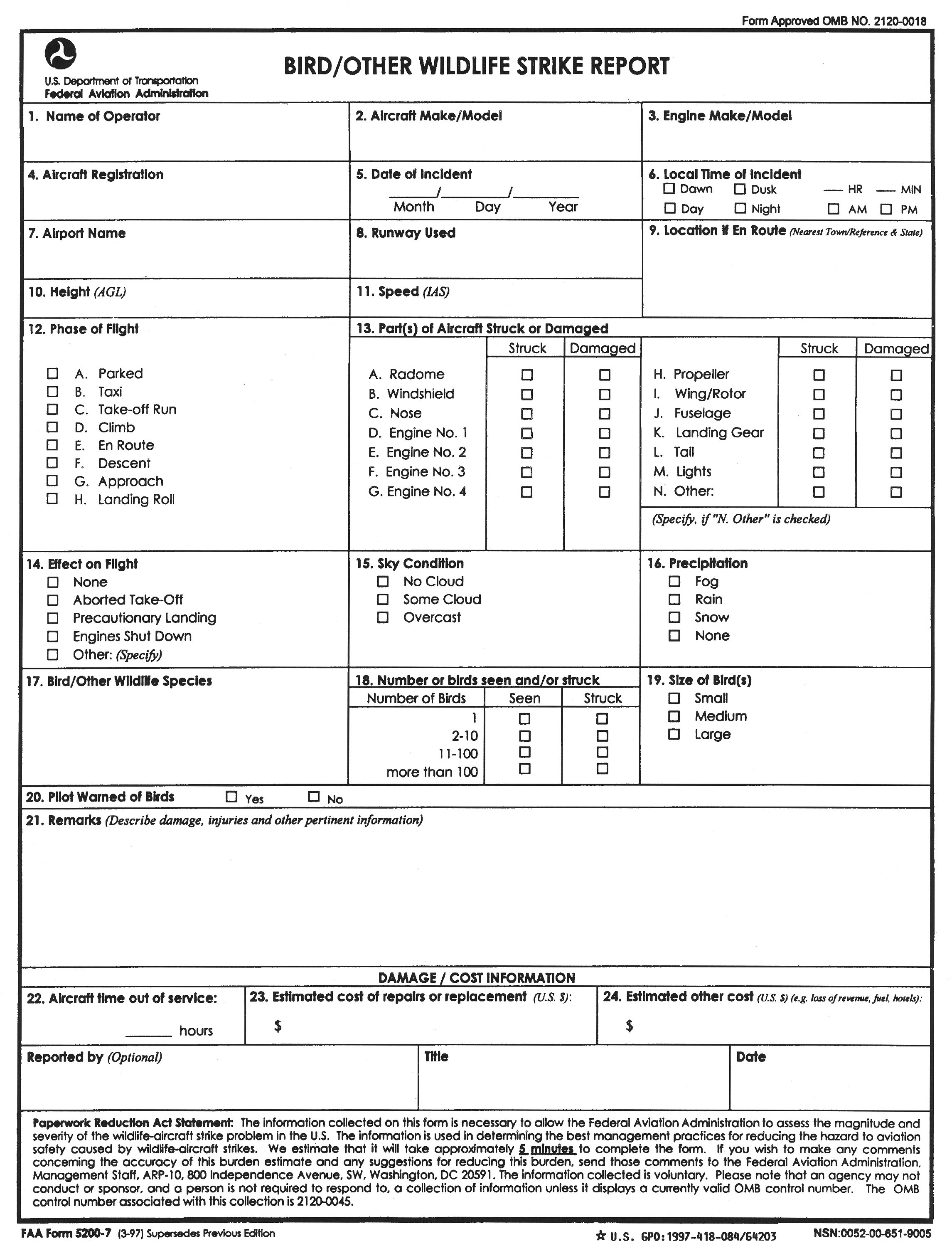
Appendix 1. Bird/Other Wildlife Strike Report
FOLD AND TAPE HERE
Appendix 2. Volcanic Activity Reporting Form (VAR)
VOLCANIC ACTIVITY REPORT
Air-reports are critically important in assessing the hazards which volcanic ash cloud presents to aircraft operations.
Date: 07/19/2010
Appendix 3. Abbreviations/Acronyms
As used in this manual, the following abbreviations/acronyms have the meanings indicated.
|
Abbreviation/Acronym |
Meaning |
|
AAWU |
Alaskan Aviation Weather Unit |
|
AAS |
Airport Advisory Service |
|
AAM |
Advanced Air Mobility |
|
AC |
Advisory Circular |
|
ACAR |
Aircraft Communications Addressing and Reporting System |
|
ADCUS |
Advise Customs |
|
ADDS |
Aviation Digital Data Service |
|
ADF |
Automatic Direction Finder |
|
ADIZ |
Air Defense Identification Zone |
|
ADS-B |
Automatic Dependent Surveillance-Broadcast |
|
AFB |
Air Force Base |
|
AFCS |
Automatic Flight Control System |
|
AFIS |
Automatic Flight Information Service |
|
AFM |
Aircraft Flight Manual |
|
AGL |
Above Ground Level |
|
AHRS |
Attitude Heading Reference System |
|
AIM |
Aeronautical Information Manual |
|
AIRMET |
Airmen's Meteorological Information |
|
AIS |
Aeronautical Information Services |
|
ALD |
Available Landing Distance |
|
ALDARS |
Automated Lightning Detection and Reporting System |
|
ALS |
Approach Light Systems |
|
AMSL |
Above Mean Sea Level |
|
ANP |
Actual Navigation Performance |
|
AOCC |
Airline Operations Control Center |
|
AP |
Autopilot System |
|
APV |
Approach with Vertical Guidance |
|
AR |
Authorization Required |
|
ARENA |
Areas Noted for Attention |
|
ARFF IC |
Aircraft Rescue and Fire Fighting Incident Commander |
|
ARINC |
Aeronautical Radio Incorporated |
|
ARO |
Airport Reservations Office |
|
ARSA |
Airport Radar Service Area |
|
ARSR |
Air Route Surveillance Radar |
|
ARTCC |
Air Route Traffic Control Center |
|
ASDE-X |
Airport Surface Detection Equipment - Model X |
|
ASOS |
Automated Surface Observing System |
|
ASR |
Airport Surveillance Radar |
|
ASRS |
Aviation Safety Reporting System |
|
ASSC |
Airport Surface Surveillance Capability |
|
ATC |
Air Traffic Control |
|
ATCRBS |
Air Traffic Control Radar Beacon System |
|
ATCSCC |
Air Traffic Control System Command Center |
|
ATCT |
Airport Traffic Control Tower |
|
ATD |
Along-Track Distance |
|
ATIS |
Automatic Terminal Information Service |
|
ATO |
Air Traffic Organization |
|
ATT |
Attitude Retention System |
|
AWC |
Aviation Weather Center |
|
AWOS |
Automated Weather Observing System |
|
AWTT |
Aviation Weather Technology Transfer |
|
AWW |
Severe Weather Forecast Alert |
|
BAASS |
Bigelow Aerospace Advanced Space Studies |
|
BBS |
Bulletin Board System |
|
BC |
Back Course |
|
BECMG |
Becoming group |
|
BVLOS |
Beyond Visual Line of Sight |
|
C/A |
Coarse Acquisition |
|
CAT |
Clear Air Turbulence |
|
CBO |
Community-Based Organization |
|
CD |
Controller Display |
|
CDI |
Course Deviation Indicator |
|
CDR |
Coded Departure Route |
|
CERAP |
Combined Center/RAPCON |
|
CFA |
Controlled Firing Area |
|
CFIT |
Controlled Flight into Terrain |
|
CFR |
Code of Federal Regulations |
|
COA |
Certificate of Waiver or Authorization |
|
CPDLC |
Controller Pilot Data Link Communications |
|
CTAF |
Common Traffic Advisory Frequency |
|
CVFP |
Charted Visual Flight Procedure |
|
CVRS |
Computerized Voice Reservation System |
|
CWA |
Center Weather Advisory |
|
CWSU |
Center Weather Service Unit |
|
DA |
Decision Altitude |
|
DCA |
Ronald Reagan Washington National Airport |
|
DCP |
Data Collection Package |
|
DER |
Departure End of Runway |
|
DH |
Decision Height |
|
DME |
Distance Measuring Equipment |
|
DME/N |
Standard DME |
|
DME/P |
Precision DME |
|
DoD |
Department of Defense |
|
DP |
Instrument Departure Procedure |
|
DPU |
Data Processor Unit |
|
DRT |
Diversion Recovery Tool |
|
DRVSM |
Domestic Reduced Vertical Separation Minimum |
|
DVA |
Diverse Vector Area |
|
DVFR |
Defense Visual Flight Rules |
|
DVRSN |
Diversion |
|
EDCT |
Expect Departure Clearance Time |
|
EFAS |
En Route Flight Advisory Service |
|
EFV |
Enhanced Flight Visibility |
|
EFVS |
Enhanced Flight Vision System |
|
ELT |
Emergency Locator Transmitter |
|
EMAS |
Engineered Materials Arresting System |
|
EPE |
Estimate of Position Error |
|
ESV |
Expanded Service Volume |
|
ETA |
Estimated Time of Arrival |
|
ETD |
Estimated Time of Departure |
|
ETE |
Estimated Time En Route |
|
EWINS |
Enhanced Weather Information System |
|
EWR |
Newark International Airport |
|
FA |
Area Forecast |
|
FAA |
Federal Aviation Administration |
|
FAF |
Final Approach Fix |
|
FAWP |
Final Approach Waypoint |
|
FB |
Fly-by |
|
FCC |
Federal Communications Commission |
|
FD |
Flight Director System |
|
FDC |
Flight Data Center |
|
FDE |
Fault Detection and Exclusion |
|
FIR |
Flight Information Region |
|
FIS |
Flight Information Service |
|
FISDL |
Flight Information Services Data Link |
|
FLIP |
Flight Information Publication |
|
FMS |
Flight Management System |
|
FO |
Fly-over |
|
FPA |
Flight Path Angle |
|
FPV |
Flight Path Vector |
|
FPNM |
Feet Per Nautical Mile |
|
FRIA |
FAA-Recognized Identification Area |
|
FSDO |
Flight Standards District Office |
|
FSS |
Flight Service Station |
|
GBAS |
Ground Based Augmentation System |
|
GEO |
Geostationary Satellite |
|
GLS |
GBAS Landing System |
|
GNSS |
Global Navigation Satellite System |
|
GNSSP |
Global Navigation Satellite System Panel |
|
GPS |
Global Positioning System |
|
GRI |
Group Repetition Interval |
|
GSD |
Geographical Situation Display |
|
GUS |
Ground Uplink Station |
|
HAT |
Height Above Touchdown |
|
HAZMAT |
Hazardous Material |
|
HDTA |
High Density Traffic Airports |
|
HEMS |
Helicopter Emergency Medical Services |
|
HIRL |
High Intensity Runway Lights |
|
HRR |
Helicopter Rapid Refueling Procedures |
|
HUD |
Head-Up Display |
|
Hz |
Hertz |
|
IAF |
Initial Approach Fix |
|
IAP |
Instrument Approach Procedure |
|
IAS |
Indicated Air Speed |
|
IAWP |
Initial Approach Waypoint |
|
ICAO |
International Civil Aviation Organization |
|
IF |
Intermediate Fix |
|
IFR |
Instrument Flight Rules |
|
ILS |
Instrument Landing System |
|
ILS/PRM |
Instrument Landing System/Precision Runway Monitor |
|
IM |
Inner Marker |
|
IMC |
Instrument Meteorological Conditions |
|
InFO |
Information For Operators |
|
INS |
Inertial Navigation System |
|
IOC |
Initial Operational Capability |
|
IR |
IFR Military Training Route |
|
IRU |
Inertial Reference Unit |
|
ITWS |
Integrated Terminal Weather System |
|
JFK |
John F. Kennedy International Airport |
|
kHz |
Kilohertz |
|
LAA |
Local Airport Advisory |
|
LAANC |
Low Altitude Authorization and Notification Capability |
|
LAAS |
Local Area Augmentation System |
|
LAHSO |
Land and Hold Short Operations |
|
LAWRS |
Limited Aviation Weather Reporting Station |
|
LDA |
Localizer Type Directional Aid |
|
LDA/PRM |
Localizer Type Directional Aid/Precision Runway Monitor |
|
LGA |
LaGuardia Airport |
|
LIRL |
Low Intensity Runway Lights |
|
LLWAS |
Low Level Wind Shear Alert System |
|
LLWAS NE |
Low Level Wind Shear Alert System Network Expansion |
|
LLWAS-RS |
Low Level Wind Shear Alert System Relocation/Sustainment |
|
LNAV |
Lateral Navigation |
|
LOC |
Localizer |
|
LOP |
Line-of-position |
|
LORAN |
Long Range Navigation System |
|
LP |
Localizer Performance |
|
LPV |
Localizer Performance with Vertical Guidance |
|
LUAW |
Line Up and Wait |
|
LZ |
Landing Zone |
|
MAHWP |
Missed Approach Holding Waypoint |
|
MAP |
Missed Approach Point |
|
MAWP |
Missed Approach Waypoint |
|
MDA |
Minimum Descent Altitude |
|
MEA |
Minimum En Route Altitude |
|
MEARTS |
Micro En Route Automated Radar Tracking System |
|
METAR |
Aviation Routine Weather Report |
|
MGOW |
Maximum Gross Operating Weight |
|
MHz |
Megahertz |
|
MIRL |
Medium Intensity Runway Lights |
|
MM |
Middle Marker |
|
MOA |
Military Operations Area |
|
MOCA |
Minimum Obstruction Clearance Altitude |
|
MRA |
Minimum Reception Altitude |
|
MRB |
Magnetic Reference Bearing |
|
MSA |
Minimum Safe Altitude |
|
MSAW |
Minimum Safe Altitude Warning |
|
MSL |
Mean Sea Level |
|
MTI |
Moving Target Indicator |
|
MTOS |
Mountain Obscuration |
|
MTR |
Military Training Route |
|
MVA |
Minimum Vectoring Altitude |
|
MWA |
Mountain Wave Activity |
|
MWO |
Meteorological Watch Office |
|
NAS |
National Airspace System |
|
NASA |
National Aeronautics and Space Administration |
|
NAVAID |
Navigational Aid |
|
NAVCEN |
Coast Guard Navigation Center |
|
NCWF |
National Convective Weather Forecast |
|
NDB |
Nondirectional Radio Beacon |
|
NEXRAD |
Next Generation Weather Radar |
|
NGA |
National Geospatial-Intelligence Agency |
|
NM |
Nautical Mile |
|
NMAC |
Near Midair Collision |
|
NOAA |
National Oceanic and Atmospheric Administration |
|
NOPAC |
North Pacific |
|
NoPT |
No Procedure Turn Required |
NOTAM | Notice to Airmen |
|
NPA |
Nonprecision Approach |
|
NRS |
Navigation Reference System |
|
NSA |
National Security Area |
|
NSW |
No Significant Weather |
|
NTSB |
National Transportation Safety Board |
|
NTZ |
No Transgression Zone |
|
NWS |
National Weather Service |
|
OAT |
Outside Air Temperature |
|
OBS |
Omni-bearing Selector |
|
ODP |
Obstacle Departure Procedure |
|
OIS |
Operational Information System |
|
OIS |
Obstacle Identification Surface |
|
OM |
Outer Marker |
|
OOP |
Operations Over People |
|
ORD |
Chicago O'Hare International Airport |
|
P/CG |
Pilot/Controller Glossary |
|
PA |
Precision Approach |
|
PAO |
Public Aircraft Operation |
|
PAPI |
Precision Approach Path Indicator |
|
PAR |
Precision Approach Radar |
|
PAR |
Preferred Arrival Route |
|
PC |
Personal Computer |
|
PDC |
Pre-departure Clearance |
|
PFD |
Personal Flotation Device |
|
PIC |
Pilot-in-Command |
|
PinS |
Point-in-Space |
|
PIREP |
Pilot Weather Report |
|
POB |
Persons on Board |
|
POFZ |
Precision Obstacle Free Zone |
|
POI |
Principal Operations Inspector |
|
PPS |
Precise Positioning Service |
|
PRM |
Precision Runway Monitor |
|
PT |
Procedure Turn |
|
QICP |
Qualified Internet Communications Provider |
|
RA |
Resolution Advisory |
|
RAA |
Remote Advisory Airport |
|
RAIM |
Receiver Autonomous Integrity Monitoring |
|
RAIS |
Remote Airport Information Service |
|
RBDT |
Ribbon Display Terminals |
|
RC |
Radio-Controlled |
|
RCAG |
Remote Center Air/Ground |
|
RCC |
Rescue Coordination Center |
|
RCLS |
Runway Centerline Lighting System |
|
RCO |
Remote Communications Outlet |
|
RID |
Remote Identification |
|
RPIC |
Remote Pilot-in-Command |
|
RD |
Rotor Diameter |
|
REIL |
Runway End Identifier Lights |
|
REL |
Runway Entrance Lights |
|
RFM |
Rotorcraft Flight Manual |
|
RLIM |
Runway Light Intensity Monitor |
|
RMI |
Radio Magnetic Indicator |
|
RNAV |
Area Navigation |
|
RNP |
Required Navigation Performance |
|
ROC |
Required Obstacle Clearance |
|
RPAT |
RNP Parallel Approach Runway Transitions |
|
RVR |
Runway Visual Range |
|
RVSM |
Reduced Vertical Separation Minimum |
|
RWSL |
Runway Status Light |
|
SAA |
Sense and Avoid |
|
SAFO |
Safety Alerts For Operators |
|
SAM |
System Area Monitor |
|
SAR |
Search and Rescue |
|
SAS |
Stability Augmentation System |
|
SATR |
Special Air Traffic Rules |
|
SBAS |
Satellite-based Augmentation System |
|
SDF |
Simplified Directional Facility |
|
SFL |
Sequenced Flashing Lights |
|
SFR |
Special Flight Rules |
|
SFRA |
Special Flight Rules Area |
|
SGI |
Special Government Interest |
|
SIAP |
Standard Instrument Approach Procedure |
|
SID |
Standard Instrument Departure |
|
SIGMET |
Significant Meteorological Information |
|
SM |
Statute Mile |
|
SMGCS |
Surface Movement Guidance Control System |
|
SNR |
Signal-to-noise Ratio |
|
SOIA |
Simultaneous Offset Instrument Approaches |
|
SOP |
Standard Operating Procedure |
|
SPC |
Storm Prediction Center |
|
SPS |
Standard Positioning Service |
|
STAR |
Standard Terminal Arrival |
|
STARS |
Standard Terminal Automation Replacement System |
|
STMP |
Special Traffic Management Program |
|
sUAS |
Small UAS |
|
TA |
Traffic Advisory |
|
TAA |
Terminal Arrival Area |
|
TAC |
Terminal Area Chart |
|
TACAN |
Tactical Air Navigation |
TAF | Aerodrome Forecast |
|
TAS |
True Air Speed |
|
TCAS |
Traffic Alert and Collision Avoidance System |
|
TCH |
Threshold Crossing Height |
|
TD |
Time Difference |
|
TDLS |
Tower Data Link System |
|
TDWR |
Terminal Doppler Weather Radar |
|
TDZ |
Touchdown Zone |
|
TDZE |
Touchdown Zone Elevation |
|
TDZL |
Touchdown Zone Lights |
|
TEC |
Tower En Route Control |
|
THL |
Takeoff Hold Lights |
|
TIS |
Traffic Information Service |
|
TIS-B |
Traffic Information Service-Broadcast |
|
TLS |
Transponder Landing System |
|
TPP |
Terminal Procedures Publications |
|
TRSA |
Terminal Radar Service Area |
|
TRUST |
The Recreational UAS Safety Test |
|
TSO |
Technical Standard Order |
|
TWIB |
Terminal Weather Information for Pilots System |
|
U.S. |
United States |
|
UA |
Unmanned Aircraft |
|
UAM |
Urban Air Mobility |
|
UAS |
Unmanned Aircraft System |
|
UASFM |
UAS Facility Map |
|
UAV |
Unmanned Aerial Vehicle |
|
UFO |
Unidentified Flying Object |
|
UHF |
Ultrahigh Frequency |
|
USCG |
United States Coast Guard |
|
UTC |
Coordinated Universal Time |
|
UTM |
UAS Traffic Management |
|
UWS |
Urgent Weather SIGMET |
|
UWS |
Urgent Weather SIGMET |
|
VAR |
Volcanic Activity Reporting |
|
VASI |
Visual Approach Slope Indicator |
|
VCOA |
Visual Climb Over the Airport |
|
VDA |
Vertical Descent Angle |
|
VDP |
Visual Descent Point |
|
VFR |
Visual Flight Rules |
|
VGSI |
Visual Glide Slope Indicator |
|
VHF |
Very High Frequency |
|
VIP |
Video Integrator Processor |
|
VLOS |
Visual Line of Sight |
|
VMC |
Visual Meteorological Conditions |
|
VMINI |
Instrument flight minimum speed, utilized in complying with minimum limit speed requirements for instrument flight |
|
VNAV |
Vertical Navigation |
|
VNE |
Never exceed speed |
|
VNEI |
Instrument flight never exceed speed, utilized instead of VNE for compliance with maximum limit speed requirements for instrument flight |
|
VO |
Visual Observer |
|
VOR |
Very High Frequency Omni-directional Range |
|
VORTAC |
VHF Omni-directional Range/Tactical Air Navigation |
|
VOT |
VOR Test Facility |
|
VR |
VFR Military Training Route |
|
VREF |
The reference landing approach speed, usually about 1.3 times Vso plus 50 percent of the wind gust speed in excess of the mean wind speed. |
|
VSO |
The stalling speed or the minimum steady flight speed in the landing configuration at maximum weight. |
|
VTF |
Vector to Final |
|
VV |
Vertical Visibility |
|
VVI |
Vertical Velocity Indicator |
|
VY |
Speed for best rate of climb |
|
VYI |
Instrument climb speed, utilized instead of VY for compliance with the climb requirements for instrument flight |
|
WA |
AIRMET |
|
WAAS |
Wide Area Augmentation System |
|
WFO |
Weather Forecast Office |
|
WGS-84 |
World Geodetic System of 1984 |
|
WMO |
World Meteorological Organization |
|
WMS |
Wide-Area Master Station |
|
WMSC |
Weather Message Switching Center |
|
WMSCR |
Weather Message Switching Center Replacement |
|
WP |
Waypoint |
|
WRA |
Weather Reconnaissance Area |
|
WRS |
Wide-Area Ground Reference Station |
|
WS |
SIGMET |
|
WSO |
Weather Service Office |
|
WSP |
Weather Systems Processor |
|
WST |
Convective Significant Meteorological Information |
|
WW |
Severe Weather Watch Bulletin |
Appendix 4. FAA Form 7233-4 - International Flight Plan
a. The FAA will accept a flight plan in international format for IFR, VFR, SFRA, and DVFR flights. File the flight plan electronically via a Flight Service Station (FSS), FAA contracted flight plan filing service, or other commercial flight plan filing service. Depending on the filing service chosen, the method of entering data may be different but the information required is generally the same.
b. The international flight plan format is mandatory for:
1. Any flight plan filed through a FSS or FAA contracted flight plan filing service; with the exception of Department of Defense flight plans and civilian stereo route flight plans, which can still be filed using the format prescribed in FAA Form 7233-1.
NOTE-
DoD Form DD-175 and FAA Form 7233-1 are considered to follow the same format.
2. Any flight that will depart U.S. domestic airspace. For DoD flight plan purposes, offshore Warning Areas may use FAA Form 7233-1 or military equivalent.
3. Any flight requesting routing that requires Performance Based Navigation.
4. Any flight requesting services that require filing of capabilities only supported in the international flight plan format.
c. Flight Plan Contents
1. A flight plan will include information shown below:
(a) Flight Specific Information (TBL 4-1)
(b) Aircraft Specific Information (TBL 4-19)
(c) Flight Routing Information (TBL 4-20)
(d) Flight Specific Supplementary Information (Item 19)
2. The tables indicate where the information is located in the international flight plan format, the information required for U.S. domestic flights, and the location of equivalent information in the domestic flight plan format.
3. International flights, including those that temporarily leave domestic U.S. airspace and return, require all applicable information in the international flight plan. Additional information can be found in ICAO Doc. 4444 (Procedures for Air Navigation Services, Air Traffic Management), and ICAO Doc. 7030 (Regional Supplemental Procedures) as well as the Aeronautical Information Publications (AIPs), Aeronautical Information Circulars (AICs), and NOTAMs of applicable other countries.
TBL 4-1
Flight Specific Information
|
Item |
International Flight |
Domestic U.S. Requirements |
Equivalent Item on Domestic Flight Plan (FAA Form 7233-1) |
|
Aircraft Identification |
Item 7 |
Required |
Item 2 |
|
Flight Rules |
Item 8 |
Required |
Item 1 |
|
Type of Flight |
Item 8 |
No need to file for domestic U.S. flight |
N/A |
|
Equipment and Capabilities |
Item 10 |
Required |
Item 3 |
|
Date of Flight |
Item 18 DOF/ |
Include when date of flight is not today |
N/A |
|
Reasons for Special Handling |
Item 18 STS/; RMK/ |
Include when special category is applicable |
Item 11 |
|
Remarks |
Item 18 RMK/ |
Include when necessary |
Item 11 |
|
Operator |
Item 18 OPR/ |
No need to file for domestic U.S. flight |
N/A |
|
Flight Plan Originator |
Item 18 ORGN/ |
No need to file for domestic U.S. flight |
N/A |
d. Instructions for Flight-Specific Information Items
1. Aircraft Identification (Item 7) Aircraft Identification is always required. Aircraft identification must not exceed seven alphanumeric characters and be either:
(a) The ICAO designator for the aircraft operating agency, followed by the flight identification (for example, KLM511, NGA213, JTR25). When in radiotelephony the call sign to be used by the aircraft will consist of the ICAO telephony designator for the operating agency followed by the flight identification (for example, KLM511, NIGERIA213, JESTER25);
(b) The nationality or common mark and registration of the aircraft (for example, EIAKO, 4XBCD, N2567GA), when:
(1) In radiotelephony, the call sign to be used by the aircraft will consist of this identification alone (for example, CGAJS) or preceded by the ICAO telephony designator for the aircraft operating agency (for example, BLIZZARD CGAJS); or
(2) The aircraft is not equipped with radio.
NOTE-
1. Standards for nationality, common and registration marks to be used are contained in Annex 7, Chapter 2.
2. Provisions for using radiotelephony call signs are contained in Annex 10, Volume II, Chapter 5. ICAO designators and telephony designators for aircraft operating agencies are contained in Doc 8585—Designators for Aircraft Operating Agencies, Aeronautical Authorities and Services.
NOTE-
Some countries' aircraft identifications begin with a number, which cannot be processed by U.S. ATC automation. The FAA will add a leading letter temporarily to gain automation acceptance for aircraft identifications that begin with a numeral. For flight-processing systems (e.g., ERAM or STARS) which will not accept a call sign that begins with a number, if the call sign is 6 characters or less, add a Q at the beginning of the call sign. If the call sign is 7 characters, delete the first character and replace it with a Q. Put the original call sign in the remarks section of the flight plan.
EXAMPLE-
9HRA becomes Q9HRA
5744233 becomes Q744233
2. Flight Rules (Item 8a)
(a) Flight rules are always required.
(b) Flight rules must indicate IFR (I) or VFR (V).
(c) For composite flight plans, submit separate flight plans for the IFR and VFR portions of the flight. Specify in Item 15 the point or points where change of flight rules is planned. The IFR plan will be routed to ATC, and the VFR plan will be routed to a Flight Service for Search and Rescue services.
NOTE-
The pilot is responsible for opening and closing the VFR flight plan. ATC does not have knowledge of a VFR flight plan's status.
3. Type of Flight (Item 8b)
(a) The type of flight is optional for flights remaining wholly within U.S. domestic airspace.
(b) Indicate the type of flight as follows:
• G - General Aviation
• S - Scheduled Air Service
• N - Non-Scheduled Air Transport Operation
• M - Military
• X - other than any of the defined categories above
4. Equipment and Capabilities (Item 10, Item 18 NAV/, COM/, DAT/, SUR/)
(a) Equipment and capabilities that can be filed in a flight plan include:
• Navigation capabilities in Item 10a, Item 18 PBN/, and Item 18 NAV/
• Voice communication capabilities in Item 10a and Item 18 COM/
• Data communication capabilities in Item 10a and Item 18 DAT/
• Approach capabilities in Item 10a and Item 18 NAV/
• Surveillance capabilities in Item 10b and Item 18 SUR/
(b) Codes allowed in Item 10a are shown in Table 4-2. Codes allowed in Item 10b are shown in TBL 4-3. Codes recognized in Item 18 NAV/, COM/, DAT/, and SUR/ are shown in TBL 4-4. Note that other service providers may define additional allowable (and required) codes for use in Item 18 NAV/, COM/, DAT/, or SUR/. Codes to designate PBN capability are described in TBL 4-5.
Radio communication, navigation and approach aid equipment and capabilities
ENTER one letter as follows:
N if no COM/NAV/approach aid equipment for the route to be flown is carried, or the equipment is unserviceable,
OR
S if standard COM/NAV/approach aid equipment for the route to be flown is carried and serviceable (see Note 1),
AND/OR
ENTER one or more of the following letters from TBL 4-2 to indicate the serviceable COM/NAV/ approach aid equipment and capabilities available.
TBL 4-2
Item 10a Navigation, Communication, and Approach Aid Capabilities
Any alphanumeric characters not indicated above are reserved.
NOTE-
1. If the letter “S” is used, standard equipment is considered to be VHF RTF, VOR, and ILS, unless another combination is prescribed by the appropriate ATS authority.
2. If the letter “G” is used, the types of external GNSS augmentation, if any, are specified in Item 18 following the indicator NAV/ and separated by a space.
EXAMPLE-
NAV/SBAS
3. See RTCA/EUROCAE Interoperability Requirements Standard for ATN Baseline 1 (ATN B1 INTEROP Standard - DO -280B/ED-110B) for data link services air traffic control clearance and information/air traffic control communications management/air traffic control microphone check.
4. If the letter “R” is used, the performance-based navigation levels that can be met are specific in Item 18 following the indicator PBN/. Guidance material on the application of performance-based navigation to a specific route segment, route, or area is contained in the Performance-based Navigation (PBN) Manual (Doc 9613)
5. If the letter “Z” is used, specify in Item 18 the other equipment carried or other capabilities, preceded by COM/, NAV/, and/or DAT, as appropriate.
6. Information on navigation capability is provided to ATC for clearance and routing purposes.
7. Guidance on the application of performance-based communication, which prescribes RCP to an air traffic service in a specific area, is contained in the Performance-based Communication and Surveillance (PBCS) Manual (Doc 9869).
TBL 4-3
Item 10b Surveillance Capabilities
|
ENTER “N” if no surveillance equipment for the route to be flown is carried, or the equipment is unserviceable, or ENTER One or more of the following descriptors, to a maximum of 20 characters, to describe the serviceable surveillance equipment and/or capabilities on board.
ENTER no more than one transponder code (Modes A, C, or S) SSR Modes A and C: A Transponder Mode A (4 digits - 4096 codes) C Transponder Mode A (4 digits - 4096 codes) and Mode C SSR Mode S: E Transponder Mode S, including aircraft identification, pressure-altitude, and extended squitter (ADS-B) capability H Transponder Mode S, including aircraft identification, pressure-altitude, and enhanced surveillance capability I Transponder Mode S, including aircraft identification, but no pressure-altitude capability L Transponder Mode S, including aircraft identification, pressure-altitude, extended squitter (ADS-B), and enhanced surveillance capability P Transponder Mode S, including pressure-altitude, but no aircraft identification capability S Transponder Mode S, including both pressure-altitude and aircraft identification capability X Transponder Mode S, with neither aircraft identification nor pressure-altitude NOTE- ADS-B: B1 ADS-B with dedicated 1090 MHz ADS-B “out” capability B2 ADS-B with dedicated 1090 MHz ADS-B “out” and “in” capability U1 ADS-B with “out” capability using UAT U2 ADS-B with “out” and “in” capability using UAT V1 ADS-B with “out” capability using VDL Mode 4 V2 ADS-B with “out” and “in” capability using VDL Mode 4 NOTE- ADS-C: D1 ADS-C with FANS 1/A capabilities G1 ADS-C with ATN capabilities Alphanumeric characters not included above are reserved. EXAMPLE- NOTE- 2. List additional surveillance equipment or capabilities in Item 18 following the indicator SUR/. |
TBL 4-4
Item 18 NAV/, COM/, DAT/, and SUR/ capabilities used by FAA
|
Item |
Purpose |
Entry |
Explanation |
|
NAV/ entries used by FAA |
Radius to Fix (RF) capability |
Z1 |
RNP-capable flight is authorized for Radius to Fix operations. |
|
Fixed Radius Transitions (FRT) |
Z2 |
RNP-capable flight is authorized for Fixed Radius Transitions. |
|
|
Time of Arrival Control (TOAC) |
Z5 |
RNP-capable flight is authorized for Time of Arrival Control. |
|
|
Advanced RNP (A-RNP) |
P1 |
Flight is authorized for A-RNP operations. |
|
|
Helicopter RNP 0.3 |
R1 |
Flight is authorized for RNP 0.3 operations (pertains to helicopters only). |
|
|
RNP 2 Continental |
M1 |
Flight is authorized for RNP 2 continental operations. |
|
|
RNP 2 Oceanic/Remote |
M2 |
Flight is authorized for RNP 2 oceanic/remote operations. |
|
|
COM/ entries used by FAA |
N/A |
N/A |
The FAA currently does not use any entries in COM/. |
|
DAT/ entries used by FAA |
Capability and preference for delivery of pre-departure clearance |
Priority number followed by: |
Entries are combined with a priority number, for example; 1FANS2PDC means a preference for departure clearance delivered via FANS 1/A; with capability to also receive the clearance via ACARS PDC. |
|
SUR/ entries used by FAA |
Req. Surveillance Performance |
RSP180 |
Aircraft is authorized for Required Surveillance Performance RSP180 |
|
RSP400 |
Aircraft is authorized for Required Surveillance Performance RSP400 |
||
|
ADS-B |
A2 |
Aircraft has 1090 MHz Extended Squitter ADS-B compliant with RTCA DO-260B (complies with FAA requirements) |
|
|
A2 |
Aircraft has 978 MHz UAT ADS-B compliant with RTCA DO-282B (complies with FAA requirements) |
NOTE-
1. Other entries in NAV/, COM/, DAT/, and SUR/ are permitted for international flights when instructed by other service providers. Direction on use of these capabilities by the FAA is detailed in the following sections.
2. In NAV/, descriptors for advanced capabilities (Z1, P1, R1, M1, and M2) should be entered as a single character string with no intervening spaces, and separated from any other entries in NAV/ by a space.
EXAMPLE-
NAV/Z1P1M2 SBAS
TBL 4-5
Item 18. PBN/ Specifications
(Include as many of the applicable descriptors, up to a maximum of 8 entries (not more than 16 characters).
|
PBN/ |
RNAV SPECIFICATIONS |
|
A1 |
RNAV 10 (RNP 10) |
|
B1 |
RNAV 5 all permitted sensors |
|
B2 |
RNAV 5 GNSS |
|
B3 |
RNAV 5 DME/DME |
|
B4 |
RNAV 5 VOR/DME |
|
B5 |
RNAV 5 INS or IRS |
|
B6 |
RNAV 5 LORAN C |
|
C1 |
RNAV 2 all permitted sensors |
|
C2 |
RNAV 2 GNSS |
|
C3 |
RNAV 2 DME/DME |
|
C4 |
RNAV 2 DME/DME/IRU |
|
D1 |
RNAV 1 all permitted sensors |
|
D2 |
RNAV 1 GNSS |
|
D3 |
RNAV 1 DME/DME |
|
D4 |
RNAV 1 DME/DME/IRU |
|
PBN/ |
RNP SPECIFICATIONS |
|
L1 |
RNP 4 |
|
O1 |
Basic RNP 1 all permitted sensors |
|
O2 |
Basic RNP 1 GNSS |
|
O3 |
Basic RNP 1 DME/DME |
|
O4 |
Basic RNP 1 DME/DME/IRU |
|
S1 |
RNP APCH |
|
S2 |
RNP APCH with BARO-VNAV |
|
T1 |
RNP AR APCH with RF (special authorization required) |
|
T2 |
RNP AR APCH without RF (special authorization required) |
NOTE-
1. PBN Codes B1-B6 indicates RNAV 5 capability. The FAA considers these B codes to be synonymous and qualifying for point-to-point routing but not for assignment to the PBN routes shown in the table.
2. Combinations of alphanumeric characters not included above are reserved.
3. The PBN/ specifications are allowed per ICAO Doc. 4444. The FAA makes use of a subset of these codes as described in the section on filing navigation capability.
(c) The following sections detail what capabilities need to be provided to obtain services from the FAA for:
• IFR flights (general).
• Assignment of Performance-Based Navigation (PBN) routes.
• Automated Departure clearance (via Datacom DCL or PDC).
• Reduced Vertical Separation Minima (if requesting FL 290 or above).
• Reduced Separation in Oceanic Airspace.
(d) Capabilities such as voice communications, required communications performance, approach aids, and ADS-C, are not required in a flight plan that remains entirely within domestic airspace.
(e) Flights that leave domestic United States airspace may be required to include additional capabilities, per requirements for the FIRs being overflown. Consult the appropriate State Aeronautical Information Publications for requirements.
(f) Include the capability only if:
• The requisite equipment is installed and operational;
• The crew is trained as required; and
• Any required Operations Specification, Letter of Authorization, or other approvals are in hand.
NOTE-
Do not include a capability solely based on the installed equipment if an operational approval is required. For example, all U.S. civil operators require either Operations Specification, Management Specification, or Letter of Authorization B036, as applicable, in order to include NAV/M2 (RNP 2 (oceanic/remote)), PBN/A1 (RNAV 10 (RNP 10)), or PBN/L1 (RNP 4) in Item 18.
5. Filing equipment and capability in an IFR Flight Plan. This section details the minimum requirements to identify capabilities in an IFR flight plan for flights in the domestic United States. Other requirements to file a capability are associated with obtaining specific services as described in subsequent sections. The basic capabilities that must be addressed include Navigation, Transponder, Voice, and ADS-B Out as described below. A designator for “Standard” capability is also allowed to cover a suite of commonly carried voice, navigation, and approach equipment with one code.
(a) Standard Capability and No Capability (Item 10a)
• Use “S” if VHF radio, VOR, and ILS equipment for the route to be flown are carried and serviceable. Use of the 'S' removes the need to list these three capabilities separately.
• Use “N” if no communications, navigation, or approach aid equipment for the route to be flown are carried or the equipment is unserviceable.
• When there is no transponder, ADS-B, or ADS-C capability then file only the letter 'N' in Item 10b.
(b) Navigation Capabilities (Item 10a, Item 18 NAV/)
• Indicate radio navigation capability by filing one or more of the codes in TBL 4-6.
• Indicate Area Navigation (RNAV) capability by filing one or more of the codes in TBL 4-7.
TBL 4-6
Radio Navigation Capabilities
|
Capability |
Item 10a |
Item 18 NAV/ |
|
VOR |
O |
|
|
DME |
D |
|
|
TACAN |
T |
|
TBL 4-7
Area Navigation Capabilities
|
Capability |
Item 10a |
Item 18 NAV/ |
|
GNSS |
G |
SBAS (if WAAS equipped) |
|
INS |
I |
|
|
DME / DME |
DR |
|
|
VOR / DME |
DOR |
|
NOTE-
1. SBAS - Space-Based Augmentation System
GBAS - Ground-Based Augmentation System
2. No PBN/ code needs to be filed to indicate the ability to fly point-to-point routes using GNSS or INS.
3. Filing one of these four area navigation capabilities as shown does not indicate performance based navigation sufficient for flying Q-Routes, T-Routes, or RNAV SIDs or STARs. To qualify for these routes, see the section on Performance Based Navigation Routes.
(c) Transponder Capabilities (Item 10b)
• For domestic flights, it is not necessary to indicate Mode S capability. It is acceptable to simply file one of the following codes in TBL 4-8.
TBL 4-8
Mode C
|
Capability |
Item 10b |
|
Transponder with no Mode C |
A |
|
Transponder with Mode C |
C |
• International flights must file in accordance with relevant AIPs and regional supplements. Include one of the Mode S codes in TBL 4-9, if appropriate.
NOTE-
File only one transponder code.
TBL 4-9
Mode S
|
Capability |
Aircraft ID |
Altitude Encoding |
Item 10b |
|
Mode S Transponder |
No |
No |
X |
|
Mode S Transponder |
No |
Yes |
P |
|
Mode S Transponder |
Yes |
No |
I |
|
Mode S Transponder |
Yes |
Yes |
S |
|
Mode S Transponder with Extended Squitter |
Yes |
Yes |
E |
|
Enhanced Mode S Transponder |
Yes |
Yes |
H |
|
Enhanced Mode S Transponder with Extended Squitter |
Yes |
Yes |
L |
(d) ADS-B Capabilities (Item 10b, Item 18 SUR/ and Item 18 CODE/)
• Indicate ADS-B capability as shown in TBL 4-10. The accompanying entry in Item 18 indicates that the equipment is compliant with 14 CFR §91.227. Some ADS-B equipment used in other countries is based on an earlier standard and does not meet U.S. requirements.
• Do not file an ADS-B code for “in” capability only. There is currently no way to indicate that an aircraft has “in” capability but no “out” capability.
• For aircraft with ADS-B “out” on one frequency and “in” on another, include only the ADS-B “out” code. For example, B1 or U1, (See TBL 4-10).
TBL 4-10
ADS-B Capabilities
|
Capability |
Item 10b |
Item 18 SUR/ |
|
1090 ES Out Capability |
B1 |
A2 |
|
1090 ES Out and In Capability |
B2 |
A2 |
|
UAT Out Capability |
U1 |
A2 |
|
UAT Out and In Capability |
U2 |
A2 |
(e) Voice Communication Capabilities (Item 10a)
The FAA does not require indication of voice communication capabilities in a flight plan for domestic flights, but it is permissible. For flights outside the domestic United States, all relevant capabilities must be indicated as follows (See TBL 4-11):
TBL 4-11
Voice Communication Capabilities
|
Capability |
Item 10a |
|
VHF Radio |
V |
|
UHF Radio |
U |
|
HF Radio |
H |
|
VHF Radio (8.33 kHZ Spacing) |
Y |
|
ATC SATVOICE (INMARSAT) |
M1 |
|
ATC SATVOICE (Iridium) |
M3 |
(f) Approach Aid Capabilities (Item 10a).
The FAA does not require filing of approach aid capability in order to request a specific type of approach, however any of the codes indicated in TBL 4-12 in 10a are permissible.
• International flights may be required to indicate approach capability, based on instructions from relevant service providers.
TBL 4-12
Approach Aid Capabilities
|
Capability |
Item 10a |
|
ILS |
L |
|
MLS |
K |
|
LPV Approach (APV with SBAS) (WAAS) |
B |
|
GBAS Landing System (LAAS) |
A |
6. Performance-Based Navigation Routes (Item 10a, Item 18 PBN/, Item 18 NAV/)- When planning to fly routes that require PBN capability, file the appropriate capability as shown in TBL 4-13.
TBL 4-13
Filing for Performance Based Navigation (PBN) Routes
|
Type of Routing |
Capability Required |
Item 10a |
Item 18 PBN/ See NOTE 2 |
Item 18 NAV/ See NOTE 3 |
Notes |
|
RNAV SID or STAR (See NOTE 1) |
RNAV 1 |
GR |
D2 |
|
If GNSS |
|
DIR |
D4 |
|
If DME/DME/IRU |
||
|
RNP SID or STAR (See NOTE 2) |
RNP 1 |
GR |
O2 |
|
If GNSS only |
|
RNP 1 |
DGIR |
O1 |
|
If GNSS primary and DME/DME/IRU backup |
|
|
RNP SID or STAR with RF required (See NOTE 2) |
RNP 1 |
GRZ |
O2 |
Z1 |
If GNSS only |
|
RNP 1 |
DGIRZ |
O1 |
Z1 |
If GNSS primary and DME/DME/IRU backup |
|
|
Domestic Q-Route (see separate requirements for Gulf of America Q-Routes) |
RNAV 2 |
GR |
C2 |
|
If GNSS |
|
DIR |
C4 |
|
If DME/DME/IRU |
||
|
T-Route |
RNAV 2 |
GR |
C2 |
|
GNSS is required for T-Routes |
|
RNAV (GPS) Approach |
RNP Approach, GPS |
GR |
S1 |
|
Domestic arrivals do not need to file PBN approach capabilities to request the approach. |
|
RNAV (GPS) Approach |
RNP Approach, GPS Baro-VNAV |
GR |
S2 |
|
|
|
RNAV (GPS) Approach with RF required |
RNP Approach, GPS |
GRZ |
S2 |
Z1 |
|
|
RNP AR Approach with RF |
RNP (Special Authorization Required) RF Leg Capability |
GR |
T1 |
|
|
|
RNP AR Approach without RF |
RNP (Special Authorization Required) |
GR |
T2 |
|
NOTE-
1. If the flight is requesting an RNAV SID only (no RNAV STAR) or RNAV STAR only (no RNAV SID) then consult guidance on the FAA website athttps://www.faa.gov/about/office_org/headquarters_offices/ato/service_units/air_traffic_services/flight_plan_filing.
2. PBN descriptor D1 includes the capabilities of D2, D3, and D4. PBN descriptor B1 includes the capabilities of B2, B3, B4, and B5. PBN descriptor C1 includes the capabilities of C2, C3, and C4.
3. In NAV/, descriptors for advanced capabilities (Z1, P1, R1, M1, and M2) should be entered as a single character string with no intervening spaces, and separated from any other entries in NAV/ by a space.
EXAMPLE-
NAV/Z1P1M2 SBAS
7. Automated Departure Clearance Delivery (DCL or PDC). When planning to use automated pre-departure clearance delivery capability, file as indicated below.
(a) PDC provides pre-departure clearances from the FAA to the operator's designated flight operations center, which then delivers the clearance to the pilot by various means. Use of PDC does not require any special flight plan entry.
(b) DCL provides pre-departure clearances from the FAA directly to the cockpit/FMS via Controller Pilot Datalink Communications (CPDLC). Use of DCL requires flight plan entries as follows:
• Include CPDLC codes in Item 10a only if the flight is capable of en route/oceanic CPDLC, the codes are not required for DCL.
• Include Z in Item 10a to indicate there is information provided in Item 18 DAT/.
• Include the clearance delivery methods of which the flight is capable, and order of preference in Item 18 DAT/. (See AIM 5-2-2)
○ VOICE - deliver clearance via Voice
○ PDC - deliver clearance via PDC
○ FANS - deliver clearance via FANS 1/A
○ FANSP - deliver clearance via FANS 1/A+
EXAMPLE-
DAT/1FANS2PDC
DAT/1FANSP2VOICE
8. Operating in Reduced Vertical Separation Minima (RVSM) Airspace (Item 10a). When planning to fly in RVSM airspace (FL 290 up to and including FL 410) then file as indicated below.
(a) If capable and approved for RVSM operations, per AIM 4-6-1, Applicability and RVSM Mandate (Date/Time and Area), file a W in Item 10a. Include the aircraft registration mark in Item 18 REG/, which is used to post-operationally monitor the safety of RVSM operations.
• Do not file a “W” in Item 10a if the aircraft is capable of RVSM operations, but is not approved to operate in RVSM airspace.
• If RVSM capability is lost after the flight plan is filed, request that ATC remove the 'W' from Item 10a.
(b) When requesting to operate non-RVSM in RVSM airspace, using one of the exceptions identified in AIM 4-6-10, do not include a “W” in Item 10a. Include STS/NONRVSM in Item 18. STS/NONRVSM is used only as part of a request to operate non-RVSM in RVSM airspace.
9. Eligibility for Reduced Oceanic Separation. Indicate eligibility for the listed reduced separation minima as indicated in the tables below. Full Operational Requirements for these services are found in the U.S. Aeronautical Information Publication (AIP) ENR 7, Oceanic Operations, available at http://www.faa.gov/air_traffic/publications/atpubs/aip_html/index.html.
TBL 4-14
Filing for Gulf of America CTA
|
Dimension of Separation |
Separation Minima |
ADS-C Surveillance Requirements |
Comm. Requirement |
PBN Requirement
|
Flight Plan Entries |
|||
|
ADS-C in Item 10b |
CPDLC in Item 10a |
PBN in Item 18 PBN/ |
PBN in Item 18 NAV/ |
|||||
|
Lateral |
50 NM |
N/A |
Voice comm-HF or VHF as required to maintain contact over the entire route to be flown. |
RNP10 |
N/A |
N/A |
A1 or L1 |
N/A |
NOTE-
If not RNAV10/RNP10 capable and planning to operate in the Gulf of America CTA, then put the notation NONRNP10 in Item 18 RMK/, preferably first.
TBL 4-15
Filing for 50 NM Lateral Separation in Anchorage Arctic FIR
|
Dimension of Separation |
Separation Minima |
ADS-C Surveillance Requirements |
Comm. Requirement |
PBN Requirement
|
Flight Plan Entries |
|||
|
ADS-C in Item 10b |
CPDLC in Item 10a |
PBN in Item 18 PBN/ |
PBN in Item 18 NAV/ |
|||||
|
Lateral |
50 NM |
N/A |
None beyond normal requirements for the airspace |
RNP10 or RNP4 |
N/A |
N/A |
A1 or L1 |
N/A |
TBL 4-16
Filing for 30 NM Lateral, 30 NM Longitudinal, and 50 NM Longitudinal Oceanic Separation
in Anchorage, Oakland, and New York Oceanic CTAs
|
Dimension of Separation |
Separation Minima |
ADS-C Surveillance Requirements |
Comm. Requirement |
PBN Requirement |
Flight Plan Entries |
|||
|
ADS-C in Item 10b |
CPDLC in Item 10a |
PBN in Item 18 PBN/ |
PBN in Item 18 NAV/ |
|||||
|
Longitudinal |
50 NM |
Position report at least every 27 minutes (at least every 32 minutes if both aircraft are approved for RNP-4 operations) |
CPDLC |
RNP10 |
D1 |
J5 and/or J7 |
A1 |
N/A |
|
Longitudinal |
30 NM |
ADS-C position report at least every 10 minutes |
CPDLC |
RNP4 |
D1 |
J5 and/or J7
|
L1 |
N/A |
|
Lateral |
30 NM |
ADS-C-based lateral deviation event contract with 5NM lateral deviation from planned routing set as threshold for triggering ADS report of lateral deviation event |
CPDLC |
RNP4 |
D1 |
J5 and/or J7 |
L1 |
N/A |
TBL 4-17
Filing for Reduced Oceanic Separation when RSP/RCP Required on March 29, 2018
|
Dimension of Separation |
Separation Minima |
RSP Requirement |
RCP Requirement |
PBN Requirement
|
Flight Plan Entries |
||||
|
RSP in Item 18 SUR/ |
RCP in Item 10a |
CDPLC in Item10a |
PBN in Item 18 PBN/ (also File 'R' in Item 10a) |
PBN in Item 18 NAV/ |
|||||
|
Lateral |
55.5 km |
180 |
240 |
RNP 2 or RNP 4 |
RSP180 |
P2 |
J5, and/or
|
L1 |
|
|
Performance-based |
5 Minutes |
180 |
240 |
RNAV 10 (RNP 10) RNP 4, or RNP 2 oceanic/ remote |
RSP180 |
P2 |
J5, and/or
|
A1 or L1 |
M2 |
|
Performance-based |
55.5 km |
180 |
240 |
RNP 4 or RNP 2 oceanic/ remote |
RSP180 |
P2 |
J5, and/or
|
L1 |
M2 |
|
Performance-based |
93 km |
180 |
240 |
RNAV 10 (RNP 10) or RNP 4 |
RSP180 |
P2 |
J5, and/or
|
A1 or L1 |
|
NOTE-
1. Filing of RNP 2 alone is not supported in FAA controlled airspace; PBN/L1 (for RNP 4) or PBN/A1 (for RNP 10) must be filed to obtain the indicated separation.
2. Use of “RNP2” in NAV/ signifies continental RNP 2 (and means the same as M1). Continental RNP 2 is not adequate for reduced oceanic separation. Descriptor M2 indicates RNP 2 global/oceanic RNP 2 capability.
10. Date of Flight (Item 18 DOF/)
Flights planned more than 23 hours after the time the flight plan is filed, must include the date of flight in DOF/ expressed in a six-digit format YYMMDD, where YY equals the year (Y), MM equals the month, and DD equals the day.
NOTE-
FAA ATC systems will not accept flight plans more than 23 hours prior to their proposed departure time. FAA Flight Service and commercial flight planning services generally accept flight plans earlier and forward to ATC at an appropriate time, typically 2 to 4 hours before the flight.
EXAMPLE-
DOF/171130
11. Reasons for Special Handling (Item 18 STS/)
(a) Indicate the applicable Special Handling in Item 18 STS/ as shown in TBL 4-18.
NOTE-
Priority for a flight is not automatically granted based on filing one of these codes but is based on documented procedures. In some cases, additional information may also be required in remarks; follow all such instructions as well.
TBL 4-18
Special Handling
|
Special Handling |
Item 18 STS/ |
|
Flight operating in accordance with an altitude reservation |
ALTRV |
|
Flight approved for exemption from ATFM measures by the appropriate ATS authority |
ATFMX |
|
Fire Fighting |
FFR |
|
Flight check for calibration of NAVAIDS |
FLTCK |
|
Flight carrying hazardous material(s) |
HAZMAT |
|
Flight with Head of State status |
HEAD |
|
Medical flight declared by medical authorities |
HOSP |
|
Flight operating on a humanitarian mission |
HUM |
|
Flight for which a military entity assumes responsibility for separation of military aircraft |
MARSA |
|
Life critical medical emergency evacuation |
MEDEVAC |
|
Non-RVSM capable flight intending to operate in RVSM airspace |
NONRVSM |
|
Flight engaged in a search and rescue mission |
SAR |
|
Flight engaged in military, customs, or police services |
STATE |
(b) Any other requests for special handling must be made in Item 18 RMK/.
(c) Include plain-language remarks when required by ATC or deemed necessary. Do not use special characters, for example; / * - = +.
EXAMPLE-
RMK/NRP
RMK/DVRSN
12. Remarks
Include when necessary.
13. Operator (Item 18 OPR/)
When the operator is not obvious from the aircraft identification, the operator may be indicated.
EXAMPLE-
OPR/NETJETS
14. Flight Plan Originator (Item 18 ORGN/)
(a) VFR flight plans originating outside of FAA FSS or FAA contracted flight plan filing services must enter the 8-letter AFTN address of the service where the flight plan was originally filed. Alternately, enter the name of the service where the FPL was originally filed. This information is critical to locating the FPL originator in the event additional information is needed.
(b) For IFR flight plans, the original filers AFTN address may be indicated, which is helpful in cases where a flight plan has been forwarded.
EXAMPLE-
ORGN/Acme Flight Plans
ORGN/KDENXLDS
TBL 4-19
Aircraft Specific Information
|
Item |
International Flight Plan |
Domestic U.S. Requirements |
Equivalent Item on Domestic Flight Plan (FAA Form 7233-1) |
|
Number of Aircraft |
Item 9 |
Included when more than one a/c in flight |
Item 3 |
|
Type of Aircraft |
Item 9 |
Required |
Item 3 |
|
Wake Turbulence Category |
Item 9 |
Required |
N/A |
|
Aircraft Registration |
Item 18 REG/ |
Include when planning to operate in RVSM airspace |
N/A |
|
Mode S Address |
Item 18 CODE/ |
Not required within U.S. controlled airspace |
N/A |
|
SELCAL Codes |
Item 18 SEL/ |
Include when SELCAL equipped |
N/A |
|
Performance Category |
Item 18 PER/ |
Not required for domestic flights |
N/A |
e. Instructions for Aircraft-Specific Information.
1. Number of Aircraft (Item 9) when there is more than one aircraft in the flight; indicate the number of aircraft up to 99.
2. Type of Aircraft (Item 9)
(a) Provide the appropriate 2-4 character aircraft type designator listed in FAA Order JO 7360.1, Aircraft Type Designators. FAA Order JO 7360.1 may be located at: Orders & Notices (faa.gov), then enter 7360.1 in the Search box.
(b) When there is no designator for the aircraft type use 'ZZZZ', and provide a description in Item 18 TYP/.
3. Wake Turbulence Category (Item 9)
A Wake Turbulence Category is required for all aircraft types. Provide the appropriate wake turbulence category for the aircraft type as listed in FAA Order 7360.1. The categories include:
(a) J - SUPER, aircraft types specified as such in FAA Order JO 7360.1, Aircraft Type Designators.
(b) H - HEAVY, to indicate an aircraft type with a maximum certificated take-off mass of 300,000 lbs. or more, with the exception of aircraft types listed in FAA Order JO 7360.1 in the SUPER (J) category.
(c) M - MEDIUM, to indicate an aircraft type with a maximum certificated take-off mass of less than 300,000 lbs. but more than 15,500 lbs.
(d) L - LIGHT, to indicate an aircraft type with a maximum certificated take-off mass of 15,500 lbs. or less.
4. Aircraft Registration (Item 18 REG/)
The aircraft registration must be provided here if different from the Item 7 entry. The registration mark must not include any spaces or hyphens. Additionally, the actual aircraft registration must also be included if Item 7 would have contained a leading numeric and was modified to be prefixed with the appropriate alphabetic character for U.S. ATC acceptance.
EXAMPLE-
U.S. aircraft with registration N789AK
REG/N789AK
Belgian aircraft with registration OO-FAH
REG/OOFAH
5. Mode S Address (Item 18 CODE/)
There is no U.S. requirement to file the aircraft Mode S Code in Item 18.
6. SELCAL code (Item 18 SEL/)
(a) Flights with HF radio and Selective Calling capability should include their 4-letter SELCAL code. Per the U.S. AIP, GEN 3.4, Paragraph 9, Selective Calling System (SELCAL) Facilities Available.
(b) The SELCAL is a communication system that permits the selective calling of individual aircraft over radio-telephone channels from the ground station to properly equipped aircraft, to eliminate the need for the flight crew to constantly monitor the frequency in use.
EXAMPLE-
SEL/CLEF
7. Performance Category (Item 18 PER/)
Include the appropriate single-letter Aircraft Approach Category as defined in the Pilot/Controller Glossary.
EXAMPLE-
PER/A
TBL 4-20
Flight Routing Information
|
Item |
International Flight Plan |
Domestic U.S. Requirements |
Equivalent Item on Domestic Flight Plan (FAA Form 7233-1) |
|
Departure Airport |
Item 13 |
Required |
Item 2 |
|
Departure Time |
Item 13 |
Required |
Item 1 |
|
Cruise Speed |
Item 15 |
Required |
N/A |
|
Requested Altitude |
Item 15 |
Required |
Item 3 |
|
Route |
Item 15 |
Required |
N/A |
|
Delay En Route |
Item 15, Item 18 DLE/ |
Required |
N/A |
|
Destination Airport |
Item 16 |
Required |
Item 11 |
|
Total Estimated Elapsed Time |
Item 16 |
Required |
Item |
|
Alternate Airport |
Item 16 |
If necessary |
N/A |
|
Estimated Elapsed Times |
Item 18 EET/ |
Include when filing flight plan with center other than departure center |
N/A |
f. Instructions for Flight Routing Items
1. Departure Airport (Item 13, Item 18 DEP/)
(a) Enter the departure airport. The airport should be identified using the four-letter location identifier from FAA Order JO 7350.9, Location Identifiers, or from ICAO Document 7910. FSS and FAA contracted flight plan filing services will allow up to 11 characters in the departure field. This will permit entry of non-ICAO identifier airports, and other fixes such as an intersection, fix/radial/distance, and latitude/longitude coordinates. Other electronic filing services may require a different format.
NOTE-
While user interfaces for flight plan filing are not specified, all flight plan filing services must adhere to the appropriate Interface Control Document upon transmission of the flight plan to the control facility.
(b) When the intended departure airport (Item 13) is outside of domestic U.S. airspace, or if using the paper version of FAA Form 7233-4, or DoD equivalent, if the chosen flight plan filing service does not allow non-ICAO airport identifiers in Item 13 or Item 16, use the following ICAO procedure. Enter four Z's (ZZZZ) in Item 13 and include the non-ICAO airport location identifier, fix, or waypoint location in Item 18 DEP/. A text description following the location identifier is permissible in Item 18 DEP/.
NOTE-
Use of non-ICAO identifiers in Item 13 and Item 16 is only permissible when flight destination is within U.S. airspace. If the destination is outside of the U.S., then both Item 13 and Item 16 must contain either a valid ICAO airport identifier or ZZZZ. Use of non-ICAO departure point is not permitted in Item 13 if destination in Item 16 is outside of U.S.
EXAMPLE-
DEP/MD21
DEP/W29 BAY BRIDGE AIRPORT
DEP/EMI211017
DEP/3925N07722W
2. Departure Time (Item 13)
Indicate the expected departure time using 4 digits, 2 digits for hours and 2 digits for minutes. Time is to be entered as Coordinated Universal Time (UTC).
3. Requested Cruising Speed (Item 15)
(a) Include the requested cruising speed as True Airspeed in knots using an N followed by four digits.
EXAMPLE-
N0450
(b) Indicate the requested cruising speed in Mach using an M followed by three digits.
EXAMPLE-
M081
4. Requested Cruising Altitude or Flight Level (Item 15)
(a) Indicate a Requested Flight Level using the letter F followed by 3 digits.
EXAMPLE-
F350
(b) Indicate a Requested Altitude in hundreds of feet using the letter A followed by 3 digits.
EXAMPLE-
A080
5. Route (Item 15)
Provide the requested route of flight using a combination of published routes, latitude/longitude, and/or fixes in the following formats.
(a) Consecutive fixes, lat/long points, NAVAIDs, and waypoints should be separated by the characters “DCT”, meaning direct.
EXAMPLE-
FLACK DCT IRW DCT IRW12503
4020N07205W DCT MONEY
(b) A published route should be preceded by a fix that is published on the route, indicating where the route will be joined. The published route should be followed by a fix that is published as part of the route, indicating where the route will be exited.
EXAMPLE-
DALL3 EIC V18 MEI LGC4
(c) It is acceptable to specify intended speed and altitude changes along the route by appending an oblique stroke followed by the next speed and altitude. However, note that FAA ATC systems will neither process this information nor display it to ATC personnel. Pilots are expected to maintain the last assigned altitude and request revised altitude clearances from ATC.
EXAMPLE-
DCT APN J177 LEXOR/N0467F380 J177 TAM/N0464F390 J177
6. Delay En Route (Item 15, Item 18 DLE/)
(a) ICAO defines Item 18 DLE/ to provide information about a delay en route. International flights with a delay outside U.S. domestic airspace should indicate the place and duration of the delay in Item 18 DLE/. The delay is expressed by a fix identifier followed by the duration in hours (H) and minutes (M), HHMM.
EXAMPLE-
DLE/EMI0140
(b) U.S. ATC systems will accept but not process information in DLE/. Therefore, for flights in the lower 48 states, it is preferable to include the delay as part of the route (Item 15). Delay in this format is specified by an oblique stroke (/) followed by the letter D, followed by 2 digits for hours (H) of delay, followed by a plus sign (+), followed by 2 digits for minutes (M) of delay: /DHH+MM.
EXAMPLE-
DCT EMI/D01+40 DCT MAPEL/D00+30 V143 DELRO DCT
7. Destination Airport (Item 16, Item 18 DEST/)
(a) Enter the destination airport. The airport should be identified using the four-letter location identifier from FAA Order JO 7350.9, Location Identifiers, or from ICAO Document 7910. FSS and FAA contracted flight plan filing services will allow up to 11 characters in the destination field. This will permit entry of non-ICAO identifier airports, and other fixes such as an intersection, fix/radial/distance, and latitude/longitude coordinates. Other electronic filing services may require a different format.
NOTE-
While user interfaces for flight plan filing are not specified, all flight plan filing services must adhere to the appropriate Interface Control Document upon transmission of the flight plan to the control facility.
(b) When the intended destination (Item 16) is outside of domestic U.S. airspace, or if using the paper version of FAA Form 7233-4, or if the chosen flight plan filing service does not allow non-ICAO airport identifiers in Item 13 or Item 16, use the following ICAO procedure. Enter four Z's (ZZZZ) in Item 13 and include the non-ICAO airport location identifier, fix, or waypoint location in Item 18 DEP/. A text description following the location identifier is permissible in Item 18 DEP/.
EXAMPLE-
DEST/06A MOTON FIELD
DEST/4AK6
DEST/MONTK
DEST /3925N07722W
8. Total Estimated Elapsed Time (Item 16)
All flight plans must include the total estimated elapsed time from departure to destination in hours (H) and minutes (M), format HHMM.
9. Alternate Airport (Item 16, Item 18 ALTN/)
(a) When necessary, specify an alternate airport in Item 16 using the four-letter location identifier from FAA Order 7350.9 or ICAO Document 7910. When the airport does not have a four-letter location identifier, include ZZZZ in Item 16c and file the non-standard identifier in Item 18 ALTN/.
(b) While the FAA does not require filing of alternate airports in the flight plan provided to ATC, rules for establishing alternate airports must be followed.
(c) Adding an alternate may assist during Search and Rescue by identifying additional areas to search.
(d) Although alternate airport information filed in a flight plan will be accepted by air traffic computer systems, it will not be presented to controllers. If diversion to an alternate airport becomes necessary, pilots are expected to notify ATC and request an amended clearance.
EXAMPLE-
ALTN/W50 2W2
10. Estimated Elapsed Times (EET) at boundaries or reporting points (Item 18 EET/)
EETs are required for international or oceanic flights when crossing a Flight Information Region (FIR) boundary. The EET will include the ICAO four-letter location identifier for the FIR followed by the elapsed time to the FIR boundary (e.g., KZNY0245 indicates 2 hours, 45 minutes from departure until the New York FIR boundary).
EXAMPLE-
EET/MMFR0011 MMTY0039 KZAB0105
11. Remarks (Item 18 RMK/)
Enter only those remarks pertinent to ATC or to the clarification of other flight plan information. Items of a personal nature are not accepted.
NOTE-
1. “DVRSN” should be placed in Item 11 only if the pilot/company is requesting priority handling to their original destination from ATC as a result of a diversion as defined in the Pilot/Controller Glossary.
2. Do not assume that remarks will be automatically transmitted to every controller. Specific ATC or en route requests should be made directly to the appropriate controller.
g. Flight Specific Supplemental Information (Item 19)
1. Item 19 data must be included when completing FAA Form 7233-4. This information will be retained by the facility/organization that transmits the flight plan to Air Traffic Control (ATC), for Search and Rescue purposes, but it will not be transmitted to ATC as part of the flight plan.
2. Do not include Supplemental Information as part of Item 18. The information in Item 19 is retained with the flight plan filing service for retrieval only if necessary.
NOTE-
Supplemental Information within Item 19 will be transmitted as a separate message to the destination FSS for VFR flight plans filed with a FSS or FAA contracted flight plan filing service. This will reduce the time necessary to conduct SAR actions should the flight become overdue, as this information will be readily available to the destination Flight Service Station.
3. Minimum required Item 19 entries for a domestic flight are Endurance, Persons on Board, Pilot Name and Contact Information, and Color of Aircraft. Additional entries may be required by foreign air traffic services, or at pilot discretion.
(a) After E/ Enter fuel endurance time in hours and minutes.
(b) After P/ Enter total number of persons on board using up to 30 alphanumeric characters. Enter TBN (to be notified) if the total number of persons is not known at the time of filing.
EXAMPLE-
P/005
P/TBN
P/ON FILE CAPEAIR OPERATIONS
(c) R/ (Radio) Cross out items not carried
(d) S/ (Survival Equipment) Cross out items not carried.
(e) J/ (Jackets) Cross out items not carried.
(f) D/ (Life Raft/Dinghies) Enter number carried and total capacity. Indicate if covered and color.
(g) A/ (Aircraft Color and Markings) Enter aircraft color(s).
EXAMPLE-
White Yellow Blue
4. N/ (Remarks. Not for ATC) select N if no remarks. Enter comments concerning survival equipment and information concerning personal GPS locating service, if utilized. Enter name and contact information for responsible party to verify VFR arrival/closure, if desired. Ensure party will be available for contact at ETA. (for example; FBO is open at ETA)
5. C/ (Pilot) Enter name and contact information, including telephone number, of pilot-in-command. Ensure contact information will be valid at ETA in case SAR is necessary.
FIG 4-1
FAA Form 7233-4, Pre-Flight Pilot Checklist and International Flight Plan
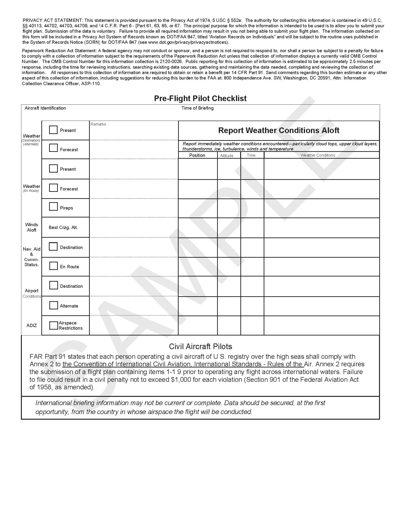
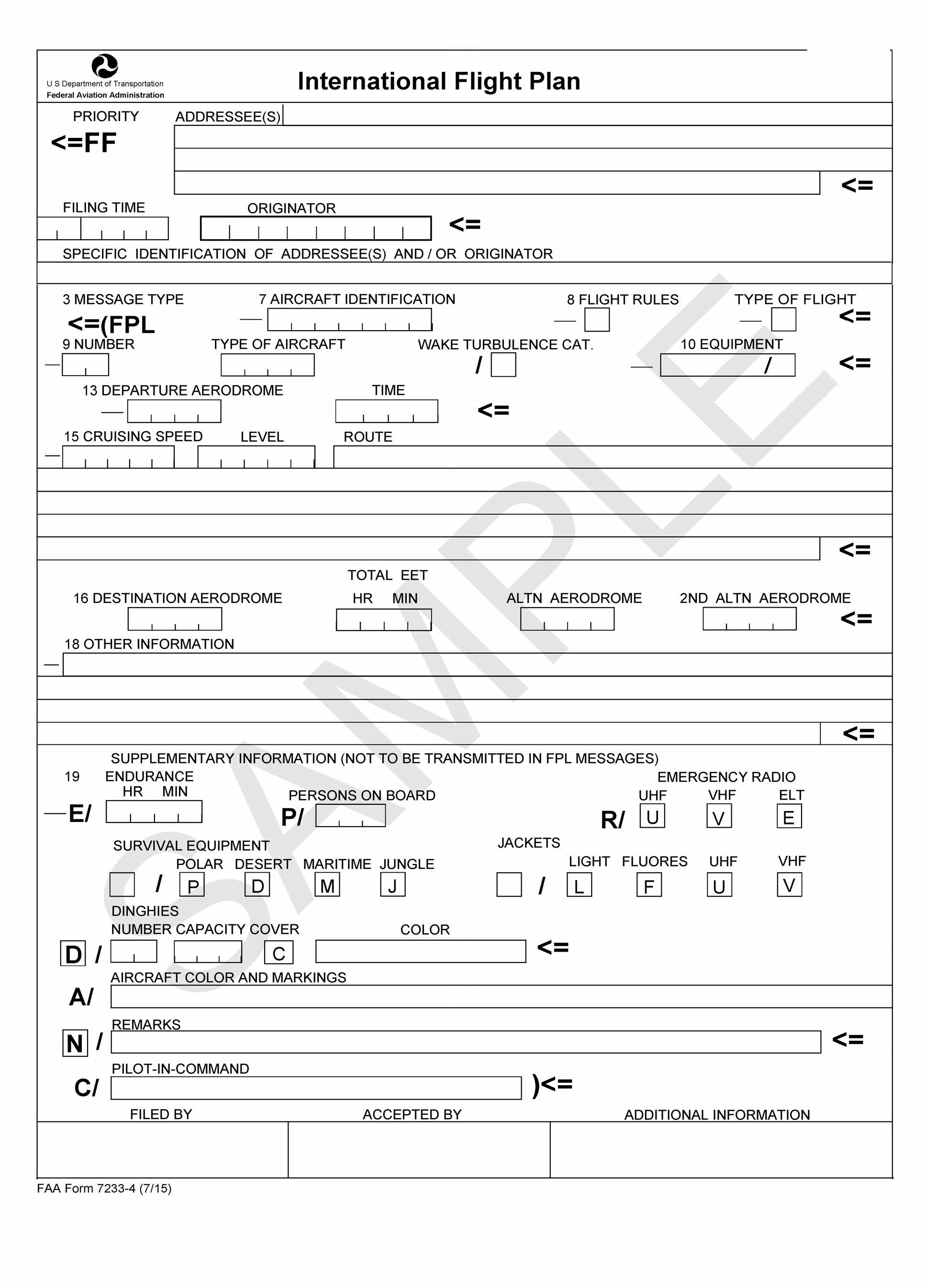
NOTE-
Current FAA Form 7233-4 available at https://www.faa.gov/forms/.
Appendix 5. FAA Form 7233-1 - Flight Plan
Throughout this document where references are made to FAA Form 7233-1, Flight Plan, and FAA Form 7233-4, International Flight Plan, DoD use of the equivalent DoD Forms 175 and 1801 respectively, are implied and acceptable. Within U.S. controlled air space, FAA Form 7233-1, Flight Plan, may be used by filers of DoD/military flight plans and civilian stereo route flight plans. Use of the international format flight plan format is mandatory for:
a. Any flight plan filed through a FSS or FAA contracted flight plan filing service; with the exception of Department of Defense flight plans and civilian stereo route flight plans, which can still be filed using the format prescribed in FAA Form 7233-1.
NOTE-
DoD Form DD-175 and FAA Form 7233-1 are considered to follow the same format.
b. Any flight that will depart U.S. domestic airspace. For DoD flight plan purposes, offshore Warning Areas may use FAA Form 7233-1 or military equivalent.
c. Any flight requesting routing that requires Performance Based Navigation.
d. Any flight requesting services that require filing of capabilities only supported in the international flight plan format.
NOTE-
The order of flight plan elements in FAA Form 7233-1 is equivalent to the DD-175.
e. Explanation of IFR/VFR Flight Plan Items.
(1) Block 1. Check the type of flight plan.
(2) Block 2. Enter your complete aircraft identification.
(3) Block 3. Enter the aircraft type.
(4) Block 4. Enter the true airspeed (TAS).
(5) Block 5. Enter the departure airport identifier.
(6) Block 6. Enter the proposed departure time in Zulu (Z). If airborne, specify the actual or proposed departure time as appropriate.
(7) Block 7. Enter the appropriate altitude.
(8) Block 8. Define the route of flight by using NAVAID identifier codes and airways.
(9) Block 9. Enter the destination airport identifier code.
(10) Block 10. Enter the estimated time en route in hours and minutes.
(11) Block 11. Enter remarks, if necessary.
(12) Block 12. Specify the fuel on board in hours and minutes.
(13) Block 13. Specify an alternate airport if desired.
(14) Block 14. Enter name and contact information for pilot in command.
NOTE-
This information is essential in the event of search and rescue operations.
(15) Block 15. Enter total number of persons on board (POB) including crew.
(16) Block 16. Enter the aircraft color.
FIG 5-1
FAA Form 7233-1 - Flight Plan
For Military/DoD, Civilian Stereo Route Flight Plan Use Only
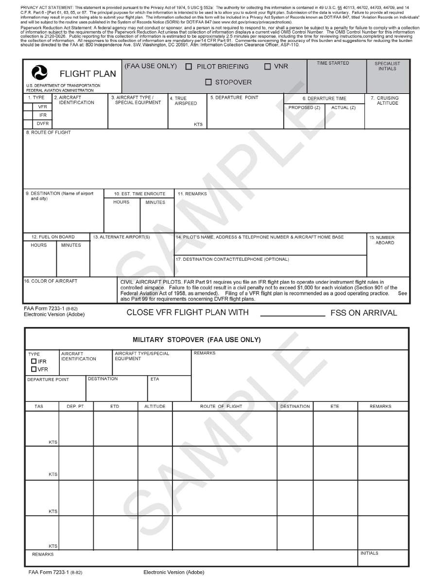
NOTE-
Current FAA Form 7233-1 available at https://www.faa.gov/forms/.