You have 0 items in your cart

FAR/AIM
>
Aeronautical Information Manual
>
Chapter 5. Air Traffic Procedures
>
Section 2. Departure Procedures
Section 2. Departure Procedures
-
Pre‐taxi Clearance Procedures
-
Certain airports have established pre‐taxi clearance programs whereby pilots of departing instrument flight rules (IFR) aircraft may elect to receive their IFR clearances before they start taxiing for takeoff. The following provisions are included in such procedures:
- Pilot participation is not mandatory.
- Participating pilots call clearance delivery or ground control not more than 10 minutes before proposed taxi time.
- IFR clearance (or delay information, if clearance cannot be obtained) is issued at the time of this initial call‐up.
- When the IFR clearance is received on clearance delivery frequency, pilots call ground control when ready to taxi.
- Normally, pilots need not inform ground control that they have received IFR clearance on clearance delivery frequency. Certain locations may, however, require that the pilot inform ground control of a portion of the routing or that the IFR clearance has been received.
- If a pilot cannot establish contact on clearance delivery frequency or has not received an IFR clearance before ready to taxi, the pilot should contact ground control and inform the controller accordingly.
- Locations where these procedures are in effect are indicated in the Chart Supplement.
-
Certain airports have established pre‐taxi clearance programs whereby pilots of departing instrument flight rules (IFR) aircraft may elect to receive their IFR clearances before they start taxiing for takeoff. The following provisions are included in such procedures:
-
Automated Pre-Departure Clearance Procedures
- Many airports in the National Airspace System are equipped with the Terminal Data Link System (TDLS) that includes the Pre-Departure Clearance (PDC) and Controller Pilot Data Link Communication-Departure Clearance (CPDLC-DCL) functions. Both the PDC and CPDLC-DCL functions automate the Clearance Delivery operations in the ATCT for participating users. Both functions display IFR clearances from the ARTCC to the ATCT. The Clearance Delivery controller in the ATCT can append local departure information and transmit the clearance via data link to participating airline/service provider computers for PDC. The airline/service provider will then deliver the clearance via the Aircraft Communications Addressing and Reporting System (ACARS) or a similar data link system, or for non-data link equipped aircraft, via a printer located at the departure gate. For CPDLC-DCL, the departure clearance is uplinked from the ATCT via the Future Air Navigation System (FANS) to the aircraft avionics and requires a response from the flight crew. Both PDC and CPDLC-DCL reduce frequency congestion, controller workload, and are intended to mitigate delivery/read back errors.
- Both services are available only to participating aircraft that have subscribed to the service through an approved service provider.
-
In all situations, the pilot is encouraged to contact clearance delivery if a question or concern exists regarding an automated clearance. Due to technical reasons, the following limitations/differences exist between the two services:
-
PDC
- Aircraft filing multiple flight plans are limited to one PDC clearance per departure airport within an 18-hour period. Additional clearances will be delivered verbally.
- If the clearance is revised or modified prior to delivery, it will be rejected from PDC and the clearance will need to be delivered verbally.
- No acknowledgment of receipt or read back is required for a PDC.
-
CPDLC-DCL
- No limitation to the number of clearances received.
- Allows delivery of revised flight data, including revised departure clearances.
- A response from the flight crew is required.
- Requires a logon to the FAA National Single Data Authority - KUSA - utilizing the ATC FANS application.
- To be eligible, operators must have received CPDLC/FANS authorization from the responsible civil aviation authority, and file appropriate equipment information in ICAO field 10a and in the ICAO field 18 DAT (Other Data Applications) of the flight plan.
-
PDC
-
IFR Clearances Off Uncontrolled Airports
- Pilots departing on an IFR flight plan should consult the Chart Supplement to determine the frequency or telephone number to use to contact clearance delivery. On initial contact, pilots should advise that the flight is IFR and state the departure and destination airports.
- Air traffic facilities providing clearance delivery services via telephone will have their telephone number published in the Chart Supplement of that airport's entry. This same section may also contain a telephone number to use for cancellation of an IFR flight plan after landing.
- Except in Alaska, pilots of MEDEVAC flights may obtain a clearance by calling 1-877-543-4733.
-
Taxi Clearance
Pilots on IFR flight plans should communicate with the control tower on the appropriate ground control or clearance delivery frequency prior to starting engines, to receive engine start time, taxi, and/or clearance information.
-
Line Up and Wait (LUAW)
-
Line up and wait is an air traffic control (ATC) procedure designed to position an aircraft onto the runway for an imminent departure. The ATC instruction “LINE UP AND WAIT” is used to instruct a pilot to taxi onto the assigned departure runway, align the aircraft with the correct departure direction and await for further ATC instructions. LUAW is not an authorization to takeoff.
EXAMPLE-
Tower: “N234AR Runway 24L, line up and wait.”
NOTE-
Previous reviews of air traffic events, involving LUAW instructions, revealed that a significant number of pilots read back LUAW instructions correctly and departed without a takeoff clearance. LUAW instructions are not to be confused with a departure clearance; the outcome could be catastrophic, especially during intersecting runway operations.
- In instances where the pilot has been instructed to LUAW and has been advised of a reason/condition (wake turbulence, traffic on an intersecting runway, etc.) or the reason/condition is clearly visible (another aircraft that has landed on or is taking off on the same runway), and the reason/condition is satisfied, the pilot should expect an imminent takeoff clearance, unless advised of a delay. If you are uncertain about any ATC instruction or clearance, contact ATC immediately.
-
If a takeoff clearance is not received within a reasonable amount of time after instructed to LUAW, ATC should be contacted.
EXAMPLE-
Aircraft: Cessna 234AR holding in position Runway 24L.
Aircraft: Cessna 234AR holding in position Runway 24L at Bravo.
NOTE-
FAA analysis of accidents and incidents involving aircraft holding in position indicate that two minutes or more elapsed between the time the instruction was issued to line up and wait and the resulting event (for example, land-over or go-around). Pilots should consider the length of time that they have been holding in position whenever they HAVE NOT been advised of any expected delay to determine when it is appropriate to query the controller.
REFERENCE-
Advisory Circulars 91-73A, Part 91 and Part 135 Single-Pilot Procedures during Taxi Operations, and 120-74A, Parts 91, 121, 125, and 135 Flightcrew Procedures during Taxi Operations.
- Situational awareness during line up and wait operations is enhanced by monitoring ATC instructions/clearances issued to other aircraft. Pilots should listen carefully if another aircraft is on frequency that has a similar call sign and pay close attention to communications between ATC and other aircraft. If you are uncertain of an ATC instruction or clearance, query ATC immediately. Care should be taken to not inadvertently execute a clearance/instruction for another aircraft.
-
Pilots should be especially vigilant when conducting LUAW operations at night, when intersecting runway operations are being conducted, or during reduced visibility conditions. Pilots should scan the full length of the runway and look for aircraft crossing the runway, on final approach, or landing roll (including intersecting runways) prior to and while taxiing onto the runway. ATC should be contacted anytime there is a concern about a potential conflict or clarity is needed with assigned instructions.
NOTE-
Pilots are reminded of the importance of maintaining situational awareness during LUAW operations with intersecting/crossing runways. Ensure a takeoff clearance has been received before beginning a takeoff roll.
- When two or more runways are active, aircraft may be instructed to “LINE UP AND WAIT” on two or more runways. When multiple runway operations are being conducted, it is important to listen closely for your call sign and runway. Be alert for similar sounding call signs and acknowledge all instructions with your call sign. When you are holding in position and are not sure if the takeoff clearance was for you, ask ATC before you begin takeoff roll. ATC prefers that you confirm a takeoff clearance rather than mistake another aircraft's clearance for your own.
-
When ATC issues intersection “line up and wait” and takeoff clearances, the intersection designator will be used. If ATC omits the intersection designator, call ATC for clarification.
EXAMPLE-
Aircraft: “Cherokee 234AR, Runway 24L at November 4, line up and wait.”
-
If landing traffic is a factor during line up and wait operations, ATC will inform the aircraft in position of the closest traffic within 6 flying miles requesting a full-stop, touch-and-go, stop-and-go, or an unrestricted low approach to the same runway. Pilots should take care to note the position of landing traffic. ATC will also advise the landing traffic when an aircraft is authorized to “line up and wait” on the same runway.
EXAMPLE-
Tower: “Cessna 234AR, Runway 24L, line up and wait. Traffic a Boeing 737, six mile final.”
Tower: “Delta 1011, continue, traffic a Cessna 210 holding in position Runway 24L.”NOTE-
ATC will normally withhold landing clearance to arrival aircraft when another aircraft is in position and holding on the runway.
-
Never land on a runway that is occupied by another aircraft, even if a landing clearance was issued. Do not hesitate to ask the controller about the traffic on the runway and be prepared to execute a go-around.
NOTE-
Always clarify any misunderstanding or confusion concerning ATC instructions or clearances. ATC should be advised immediately if there is any uncertainty about the ability to comply with any of their instructions.
-
Line up and wait is an air traffic control (ATC) procedure designed to position an aircraft onto the runway for an imminent departure. The ATC instruction “LINE UP AND WAIT” is used to instruct a pilot to taxi onto the assigned departure runway, align the aircraft with the correct departure direction and await for further ATC instructions. LUAW is not an authorization to takeoff.
-
Abbreviated IFR Departure Clearance (Cleared. . .as Filed) Procedures
-
ATC facilities will issue an abbreviated IFR departure clearance based on the ROUTE of flight filed in the IFR flight plan, provided the filed route can be approved with little or no revision. These abbreviated clearance procedures are based on the following conditions:
- The aircraft is on the ground or it has departed visual flight rules (VFR) and the pilot is requesting IFR clearance while airborne.
- That a pilot will not accept an abbreviated clearance if the route or destination of a flight plan filed with ATC has been changed by the pilot or the company or the operations officer before departure.
- That it is the responsibility of the company or operations office to inform the pilot when they make a change to the filed flight plan.
-
That it is the responsibility of the pilot to inform ATC in the initial call‐up (for clearance) when the filed flight plan has been either:
- Amended, or
-
Canceled and replaced with a new filed flight plan.
NOTE-
The facility issuing a clearance may not have received the revised route or the revised flight plan by the time a pilot requests clearance.
- Controllers will issue a detailed clearance when they know that the original filed flight plan has been changed or when the pilot requests a full route clearance.
- The clearance as issued will include the destination airport filed in the flight plan.
- ATC procedures now require the controller to state the DP name, the current number and the DP transition name after the phrase “Cleared to (destination) airport” and prior to the phrase, “then as filed,” for ALL departure clearances when the DP or DP transition is to be flown. The procedures apply whether or not the DP is filed in the flight plan.
- STARs, when filed in a flight plan, are considered a part of the filed route of flight and will not normally be stated in an initial departure clearance. If the ARTCC's jurisdictional airspace includes both the departure airport and the fix where a STAR or STAR transition begins, the STAR name, the current number and the STAR transition name MAY be stated in the initial clearance.
- “Cleared to (destination) airport as filed” does NOT include the en route altitude filed in a flight plan. An en route altitude will be stated in the clearance or the pilot will be advised to expect an assigned or filed altitude within a given time frame or at a certain point after departure. This may be done verbally in the departure instructions or stated in the DP.
-
In both radar and nonradar environments, the controller will state “Cleared to (destination) airport as filed” or:
-
If a DP or DP transition is to be flown, specify the DP name, the current DP number, the DP transition name, the assigned altitude/flight level, and any additional instructions (departure control frequency, beacon code assignment, etc.) necessary to clear a departing aircraft via the DP or DP transition and the route filed.
EXAMPLE-
National Seven Twenty cleared to Miami Airport Intercontinental one departure, Lake Charles transition then as filed, maintain Flight Level two seven zero.
-
When there is no DP or when the pilot cannot accept a DP, the controller will specify the assigned altitude or flight level, and any additional instructions necessary to clear a departing aircraft via an appropriate departure routing and the route filed.
NOTE-
A detailed departure route description or a radar vector may be used to achieve the desired departure routing.
-
If it is necessary to make a minor revision to the filed route, the controller will specify the assigned DP or DP transition (or departure routing), the revision to the filed route, the assigned altitude or flight level and any additional instructions necessary to clear a departing aircraft.
EXAMPLE-
Jet Star One Four Two Four cleared to Atlanta Airport, South Boston two departure then as filed except change route to read South Boston Victor 20 Greensboro, maintain one seven thousand.
-
Additionally, in a nonradar environment, the controller will specify one or more fixes, as necessary, to identify the initial route of flight.
EXAMPLE-
Cessna Three One Six Zero Foxtrot cleared to Charlotte Airport as filed via Brooke, maintain seven thousand.
-
If a DP or DP transition is to be flown, specify the DP name, the current DP number, the DP transition name, the assigned altitude/flight level, and any additional instructions (departure control frequency, beacon code assignment, etc.) necessary to clear a departing aircraft via the DP or DP transition and the route filed.
-
To ensure success of the program, pilots should:
- Avoid making changes to a filed flight plan just prior to departure.
-
State the following information in the initial call‐up to the facility when no change has been made to the filed flight plan: Aircraft call sign, location, type operation (IFR) and the name of the airport (or fix) to which you expect clearance.
EXAMPLE-
“Washington clearance delivery (or ground control if appropriate) American Seventy Six at gate one, IFR Los Angeles.”
-
If the flight plan has been changed, state the change and request a full route clearance.
EXAMPLE-
“Washington clearance delivery, American Seventy Six at gate one. IFR San Francisco. My flight plan route has been amended (or destination changed). Request full route clearance.”
- Request verification or clarification from ATC if ANY portion of the clearance is not clearly understood.
-
When requesting clearance for the IFR portion of a VFR/IFR flight, request such clearance prior to the fix where IFR operation is proposed to commence in sufficient time to avoid delay. Use the following phraseology:
EXAMPLE-
“Los Angeles center, Apache Six One Papa, VFR estimating Paso Robles VOR at three two, one thousand five hundred, request IFR to Bakersfield.”
-
ATC facilities will issue an abbreviated IFR departure clearance based on the ROUTE of flight filed in the IFR flight plan, provided the filed route can be approved with little or no revision. These abbreviated clearance procedures are based on the following conditions:
-
Departure Restrictions, Clearance Void Times, Hold for Release, and Release Times
-
ATC may assign departure restrictions, clearance void times, hold for release, and release times, when necessary, to separate departures from other traffic or to restrict or regulate the departure flow. Departures from an airport without an operating control tower must be issued either a departure release (along with a release time and/or void time if applicable), or a hold for release.
REFERENCE-
FAA Order JO 7110.65, Para 4-3-4, Departure Release, Hold for Release, Release Times, Departure Restrictions, and Clearance Void Times.
-
Clearance Void Times.A pilot may receive a clearance, when operating from an airport without a control tower, which contains a provision for the clearance to be void if not airborne by a specific time. A pilot who does not depart prior to the clearance void time must advise ATC as soon as possible of their intentions. ATC will normally advise the pilot of the time allotted to notify ATC that the aircraft did not depart prior to the clearance void time. This time cannot exceed 30 minutes. Failure of an aircraft to contact ATC within 30 minutes after the clearance void time will result in the aircraft being considered overdue and search and rescue procedures initiated.
NOTE-
- Other IFR traffic for the airport where the clearance is issued is suspended until the aircraft has contacted ATC or until 30 minutes after the clearance void time or 30 minutes after the clearance release time if no clearance void time is issued.
- If the clearance void time expires, it does not cancel the departure clearance or IFR flight plan. It withdraws the pilot's authority to depart IFR until a new departure release/release time has been issued by ATC and is acknowledged by the pilot.
- Pilots who depart at or after their clearance void time are not afforded IFR separation and may be in violation of 14 CFR section 91.173 which requires that pilots receive an appropriate ATC clearance before operating IFR in controlled airspace.
- Pilots who choose to depart VFR after their clearance void time has expired should not depart using the previously assigned IFR transponder code.
EXAMPLE-
Clearance void if not off by (clearance void time) and, if required, if not off by (clearance void time) advise (facility) not later than (time) of intentions.
-
Hold for Release.ATC may issue “hold for release” instructions in a clearance to delay an aircraft's departure for traffic management reasons (i.e., weather, traffic volume, etc.). When ATC states in the clearance, “hold for release,” the pilot may not depart utilizing that IFR clearance until a release time or additional instructions are issued by ATC. In addition, ATC will include departure delay information in conjunction with “hold for release” instructions. The ATC instruction, “hold for release,” applies to the IFR clearance and does not prevent the pilot from departing under VFR. However, prior to takeoff the pilot should cancel the IFR flight plan and operate the transponder/ADS-B on the appropriate VFR code. An IFR clearance may not be available after departure.
EXAMPLE-
(Aircraft identification) cleared to (destination) airport as filed, maintain (altitude), and, if required (additional instructions or information), hold for release, expect (time in hours and/or minutes) departure delay.
-
Release Times.A “release time” is a departure restriction issued to a pilot by ATC, specifying the earliest time an aircraft may depart. ATC will use “release times” in conjunction with traffic management procedures and/or to separate a departing aircraft from other traffic.
EXAMPLE-
(Aircraft identification) released for departure at (time in hours and/or minutes).
- Expect Departure Clearance Time (EDCT). The EDCT is the runway release time assigned to an aircraft included in traffic management programs. Aircraft are expected to depart no earlier than 5 minutes before, and no later than 5 minutes after the EDCT.
-
Clearance Void Times.A pilot may receive a clearance, when operating from an airport without a control tower, which contains a provision for the clearance to be void if not airborne by a specific time. A pilot who does not depart prior to the clearance void time must advise ATC as soon as possible of their intentions. ATC will normally advise the pilot of the time allotted to notify ATC that the aircraft did not depart prior to the clearance void time. This time cannot exceed 30 minutes. Failure of an aircraft to contact ATC within 30 minutes after the clearance void time will result in the aircraft being considered overdue and search and rescue procedures initiated.
- If practical, pilots departing uncontrolled airports should obtain IFR clearances prior to becoming airborne when two‐way communications with the controlling ATC facility is available.
-
ATC may assign departure restrictions, clearance void times, hold for release, and release times, when necessary, to separate departures from other traffic or to restrict or regulate the departure flow. Departures from an airport without an operating control tower must be issued either a departure release (along with a release time and/or void time if applicable), or a hold for release.
-
Departure Control
- Departure Control is an approach control function responsible for ensuring separation between departures. So as to expedite the handling of departures, Departure Control may suggest a takeoff direction other than that which may normally have been used under VFR handling. Many times it is preferred to offer the pilot a runway that will require the fewest turns after takeoff to place the pilot on course or selected departure route as quickly as possible. At many locations particular attention is paid to the use of preferential runways for local noise abatement programs, and route departures away from congested areas.
-
Departure Control utilizing radar will normally clear aircraft out of the terminal area using vectors, a diverse vector area (DVA), or published DPs.
- When a departure is to be vectored immediately following takeoff using vectors, a DVA, or published DPs that begins with an ATC assigned heading off the ground, the pilot will be advised prior to takeoff of the initial heading to be flown but may not be advised of the purpose of the heading. When ATC assigns an initial heading with the takeoff clearance that will take the aircraft off an assigned procedure (for example, an RNAV SID with a published lateral path to a waypoint and crossing restrictions from the departure end of runway), the controller will assign an altitude to maintain with the initial heading and, if necessary, a speed to maintain.
-
At some airports when a departure will fly an RNAV SID that begins at the runway, ATC may advise aircraft of the initial fix/waypoint on the RNAV route. The purpose of the advisory is to remind pilots to verify the correct procedure is programmed in the FMS before takeoff. Pilots must immediately advise ATC if a different RNAV SID is entered in the aircraft's FMC. When this advisory is absent, pilots are still required to fly the assigned SID as published.
EXAMPLE-
Delta 345 RNAV to MPASS, Runway26L, cleared for takeoff.
NOTE-
- The SID transition is not restated as it is contained in the ATC clearance.
- Aircraft cleared via RNAV SIDs designed to begin with a vector to the initial waypoint are assigned a heading before departure.
- Pilots operating in a radar environment are expected to associate departure headings or an RNAV departure advisory with vectors or the flight path to their planned route or flight. When given a vector taking the aircraft off a previously assigned nonradar route, the pilot will be advised briefly what the vector is to achieve. Thereafter, radar service will be provided until the aircraft has been reestablished “on‐course” using an appropriate navigation aid and the pilot has been advised of the aircraft's position or a handoff is made to another radar controller with further surveillance capabilities.
- Controllers will inform pilots of the departure control frequencies and, if appropriate, the transponder code before takeoff. Pilots must ensure their transponder/ADS-B is adjusted to the “on” or normal operating position as soon as practical and remain on during all operations unless otherwise requested to change to “standby” by ATC. Pilots should not change to the departure control frequency until requested. Controllers may omit the departure control frequency if a DP has or will be assigned and the departure control frequency is published on the DP.
-
Instrument Departure Procedures (DP) - Obstacle Departure Procedures (ODP), Standard Instrument Departures (SID), and Diverse Vector Areas (DVA)
- Instrument departure procedures are preplanned instrument flight rule (IFR) procedures which provide obstruction clearance from the terminal area to the appropriate en route structure. There are two types of DPs, Obstacle Departure Procedures (ODP), printed either textually or graphically, and Standard Instrument Departures (SID), always printed graphically. All DPs, either textual or graphic may be designed using either conventional or RNAV criteria. RNAV procedures will have RNAV printed in the title; for example, SHEAD TWO DEPARTURE (RNAV). ODPs provide obstruction clearance via the least onerous route from the terminal area to the appropriate en route structure. ODPs are recommended for obstruction clearance and may be flown without ATC clearance unless an alternate departure procedure (SID or radar vector) has been specifically assigned by ATC. Graphic ODPs will have (OBSTACLE) printed in the procedure title; for example, GEYSR THREE DEPARTURE (OBSTACLE), or, CROWN ONE DEPARTURE (RNAV) (OBSTACLE). Standard Instrument Departures are air traffic control (ATC) procedures printed for pilot/controller use in graphic form to provide obstruction clearance and a transition from the terminal area to the appropriate en route structure. SIDs are primarily designed for system enhancement and to reduce pilot/controller workload. ATC clearance must be received prior to flying a SID. All DPs provide the pilot with a way to depart the airport and transition to the en route structure safely.
- A Diverse Vector Area (DVA) is an area in which ATC may provide random radar vectors during an uninterrupted climb from the departure runway until above the MVA/MIA, established in accordance with the TERPS criteria for diverse departures. The DVA provides obstacle and terrain avoidance in lieu of taking off from the runway under IFR using an ODP or SID.
- Pilots operating under 14 CFR part 91 are strongly encouraged to file and fly a DP at night, during marginal Visual Meteorological Conditions (VMC) and Instrument Meteorological Conditions (IMC), when one is available. The following paragraphs will provide an overview of the DP program, why DPs are developed, what criteria are used, where to find them, how they are to be flown, and finally pilot and ATC responsibilities.
-
Why are DPs necessary? The primary reason is to provide obstacle clearance protection information to pilots. A secondary reason, at busier airports, is to increase efficiency and reduce communications and departure delays through the use of SIDs. When an instrument approach is initially developed for an airport, the need for DPs is assessed. The procedure designer conducts an obstacle analysis to support departure operations. If an aircraft may turn in any direction from a runway within the limits of the assessment area (see paragraph 5-2-9e3) and remain clear of obstacles, that runway passes what is called a diverse departure assessment and no ODP will be published. A SID may be published if needed for air traffic control purposes. However, if an obstacle penetrates what is called the 40:1 obstacle identification surface, then the procedure designer chooses whether to:
- Establish a steeper than normal climb gradient; or
- Establish a steeper than normal climb gradient with an alternative that increases takeoff minima to allow the pilot to visually remain clear of the obstacle(s); or
- Design and publish a specific departure route; or
- A combination or all of the above.
-
What criteria is used to provide obstruction clearance during departure?
-
Unless specified otherwise, required obstacle clearance for all departures, including diverse, is based on the pilot crossing the departure end of the runway at least 35 feet above the departure end of runway elevation, climbing to 400 feet above the departure end of runway elevation before making the initial turn, and maintaining a minimum climb gradient of 200 feet per nautical mile (FPNM), unless required to level off by a crossing restriction, until the minimum IFR altitude. A greater climb gradient may be specified in the DP to clear obstacles or to achieve an ATC crossing restriction. If an initial turn higher than 400 feet above the departure end of runway elevation is specified in the DP, the turn should be commenced at the higher altitude. If a turn is specified at a fix, the turn must be made at that fix. Fixes may have minimum and/or maximum crossing altitudes that must be adhered to prior to passing the fix. In rare instances, obstacles that exist on the extended runway centerline may make an “early turn” more desirable than proceeding straight ahead. In these cases, the published departure instructions will include the language “turn left(right) as soon as practicable.” These departures will also include a ceiling and visibility minimum of at least 300 and 1. Pilots encountering one of these DPs should preplan the climb out to gain altitude and begin the turn as quickly as possible within the bounds of safe operating practices and operating limitations. This type of departure procedure is being phased out.
NOTE-
“Practical” or “feasible” may exist in some existing departure text instead of “practicable.”
- ODPs, SIDs, and DVAs assume normal aircraft performance, and that all engines are operating. Development of contingency procedures, required to cover the case of an engine failure or other emergency in flight that may occur after liftoff, is the responsibility of the operator. (More detailed information on this subject is available in Advisory Circular AC 120-91, Airport Obstacle Analysis, and in the “Departure Procedures” section of chapter 2 in the Instrument Procedures Handbook, FAA-H-8083-16.)
-
The 40:1 obstacle identification surface (OIS) begins at the departure end of runway (DER) and slopes upward at 152 FPNM until reaching the minimum IFR altitude or entering the en route structure. This assessment area is limited to 25 NM from the airport in nonmountainous areas and 46 NM in designated mountainous areas. Beyond this distance, the pilot is responsible for obstacle clearance if not operating on a published route, if below (having not reached) the MEA or MOCA of a published route, or an ATC assigned altitude. See FIG 5-2-1. (Ref 14 CFR 91.177 for further information on en route altitudes.)
NOTE-
ODPs are normally designed to terminate within these distance limitations, however, some ODPs will contain routes that may exceed 25/46 NM; these routes will ensure obstacle protection until reaching the end of the ODP.
FIG 5-2-1
Diverse Departure Obstacle Assessment to 25/46 NM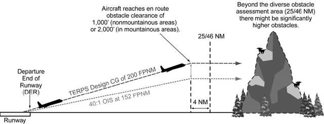
-
Takeoff Obstacles. Takeoff Obstacles Notes in the “Takeoff Minimums and (OBSTACLE) Departure Procedures” section of the Terminal Procedures Publication (TPP) identifies obstacle(s) that penetrate the 40:1 OCS. The obstacle notes alert the pilot to the height and location of the obstacles relative to the DER so they can be avoided. This can be accomplished in a variety of ways: the pilot may be able to see and avoid the obstruction; early liftoff/climb performance may allow the aircraft to cross well above the obstacle(s); or if the obstacle(s) cannot be visually acquired during departure, the takeoff should be delayed or another runway selected for the IFR departure.
-
Takeoff obstacles will be published as low, close-in and/or takeoff minimums obstacle notes.
- Low, close-in obstacles require a higher than standard climb gradient (within 1 NM or less from DER) to an altitude of 200 feet or less above DER elevation and do not require increased takeoff minimums.
- Takeoff minimums obstacles require a higher than standard climb gradient (within 2.6 NM from DER) to an altitude greater than 200 feet above the DER elevation and require increased takeoff minimums. These obstacles are published with higher than standard ceiling and visibility takeoff minimums and are published in the same obstacle listing.
- Obstacle notes are not required to be charted on SIDs. When a pilot is assigned a SID for departure refer to the airport entry in the TPP or the graphic ODP to obtain information on the takeoff obstacles.
-
The FAA redefined the initial climb area criteria that are used to evaluate and identify the obstacles that penetrate the 40:1 OCS. The takeoff obstacle notes are published in a different manner and an additional minimums option is added for the departure. To ensure the pilot knows which evaluation was accomplished, the charting will be different by bolding certain headers and runway information. Until the FAA can amend all departures the legacy obstacle notes will still be published.
- For textual departures, the headers Takeoff Minimums, Departure Procedures, and Takeoff Obstacle Notes will be bolded and underlined. The specific runway entries under each header will continue to be bolded.
- For graphic departure procedures, the headers Takeoff Minimums and Takeoff Obstacle Notes will be bolded and continue to be underlined. The specific runway entries for these headers will be bolded. In the Departure Route Description section of the graphic departure, the heading will be bolded and underlined and the runway information will just be bolded.
- Legacy takeoff obstacle notes combine low, close-in and takeoff obstacles for each runway.
- New takeoff obstacle notes separate low, close-in and takeoff minimums obstacle notes. There is also a DER crossing altitude included in the notes section, providing the pilot with a DER crossing height that clears all obstacles that penetrate the 40:1 OCS.
- The obstacles are described with an inner limit from the DER, using the word “beginning,” expressed in 1/4 SM increments rounded down and an outer limit, using the words “extending to” expressed in 1/4 SM increments rounded up. They will also be described in relation to the extended runway centerline as “left, right, or crossing.” Crossing means they are within 100ft of the centerline. Left or right means they are greater than 100 ft from centerline. Both an MSL altitude and height above DER elevation will be provided for the obstacle that penetrates the 40:1 OCS the most. This allows the pilot to determine when the reported weather conditions are adequate to see and avoid the low, close-in obstacle(s) if aircraft performance does not permit the aircraft to climb over them. It also allows the pilot to correlate the position of the obstacles and the MSL elevation and height above DER for the controlling obstacle for the published higher than standard takeoff minimums.
-
A DER crossing height using standard ceiling/visibility is provided as a new takeoff minimums option for pilots in addition to the current options (higher than standard ceiling/visibility or standard ceiling/visibility with a higher than standard climb gradient, or a reduced takeoff runway length with a standard climb gradient and standard ceiling/visibility).
EXAMPLE-
Legacy takeoff minimums and obstacle notes
TAKEOFF MINIMUMS:
Rwy12 L/R, 400-2 1/2 or std. w/min. climb of 261’ per NM to 500.
TAKEOFF OBSTACLE NOTES:
Rwy 14, trees 2011' from DER, 29' left of centerline, 100' AGL/3829' MSL.
Rwy 32, trees 1009' from DER, 697' left of centerline, 100' AGL/3839' MSL.
Tower 4448' from DER, 1036' left of centerline, 165' AGL/3886' MSL.
EXAMPLE-
New takeoff minimums and obstacle notes
TAKEOFF MINIMUMS:
Rwy12 L/R: 400-2 1/2 or std. w/min. climb of 261' per NM to 500 or standard and crossing DER 66' above DER Elev clears takeoff minimums obstacles.
TAKEOFF OBSTACLE NOTES:
Rwy 12L LOW, CLOSE-IN OBSTACLES: trees beginning 600' from DER, extending to 1/2 SM, crossing centerline, up to 156' MSL, 86' above DER, crossing DER 49' above DER Elev clears low, close-in obstacles.
Rwy 12L TAKEOFF MINIMUMS OBSTACLES: buildings, crane, tower beginning 1 1/2 SM from DER, extending to 1 3/4 SM, left, right, and crossing centerline, up to 373' MSL, 284' above DER, crossing DER at 66' above DER Elev clears takeoff minimums obstacles.
Rwy 12R LOW, CLOSE-IN OBSTACLES: obstacles 35' and below.
Rwy 12R TAKEOFF MINIMUMS OBSTACLES: buildings, crane, tower beginning 1 1/2 SM from DER, extending to 1 3/4 SM, left, right, and crossing centerline, up to 373' MSL, 284' above DER, crossing DER at 66' above DER Elev clears takeoff minimums obstacles.
Rwy 30L/R LOW, CLOSE-IN OBSTACLES: obstacles 35' and below.
- Compliance with 14 CFR part 121 or 135 one-engine-inoperative (OEI) departure performance requirements, or similar ICAO/State rules, cannot be assured by the sole use of takeoff obstacle note data as published in the TPP. Operators conducting these operations should refer to precise data sources (GIS database, etc.) specifically intended for OEI departure planning (see AC 120-91).
-
Takeoff obstacles will be published as low, close-in and/or takeoff minimums obstacle notes.
-
Climb gradients greater than 200 FPNM are specified when required to support procedure design constraints, obstacle clearance, and/or airspace restrictions. Compliance with a climb gradient for these purposes is mandatory when the procedure is part of the ATC clearance, unless increased takeoff minimums are provided and weather conditions allow compliance with these minimums.
NOTE-
Climb gradients for ATC purposes are being phased out on SIDs.
EXAMPLE-
“Cross ALPHA intersection at or below 4000; maintain 6000.” The pilot climbs at least 200 FPNM to 6000. If 4000 is reached before ALPHA, the pilot levels off at 4000 until passing ALPHA; then immediately resumes at least 200 FPNM climb.
EXAMPLE-
“TAKEOFF MINIMUMS: RWY 27, Standard with a minimum climb of 280' per NM to 2500.” A climb of at least 280 FPNM is required to 2500 and is mandatory when the departure procedure is included in the ATC clearance.
NOTE-
Some SIDs still retain labeled “ATC” climb gradients published or have climb gradients that are established to meet a published altitude restriction that is not required for obstacle clearance or procedure design criteria. These procedures will be revised in the course of the normal procedure amendment process.
-
Climb gradients may be specified only to an altitude/fix, above which the normal gradient applies. An ATC-required altitude restriction published at a fix, will not have an associated climb gradient published with that restriction. Pilots are expected to determine if crossing altitudes can be met, based on the performance capability of the aircraft they are operating.
EXAMPLE-
“Minimum climb 340 FPNM to ALPHA.” The pilot climbs at least 340 FPNM to ALPHA, then at least 200 FPNM to MIA.
-
A Visual Climb Over Airport (VCOA) procedure is a departure option for an IFR aircraft, operating in visual meteorological conditions equal to or greater than the specified visibility and ceiling, to visually conduct climbing turns over the airport to the published “at or above” altitude. At this point, the pilot may proceed in instrument meteorological conditions to the first en route fix using a diverse departure, or to proceed via a published routing to a fix from where the aircraft may join the IFR en route structure, while maintaining a climb gradient of at least 200 feet per nautical mile. VCOA procedures are developed to avoid obstacles greater than 3 statute miles from the departure end of the runway as an alternative to complying with climb gradients greater than 200 feet per nautical mile. Pilots are responsible to advise ATC as early as possible of the intent to fly the VCOA option prior to departure. Pilots are expected to remain within the distance prescribed in the published visibility minimums during the climb over the airport until reaching the “at or above” altitude for the VCOA procedure. If no additional routing is published, then the pilot may proceed in accordance with their IFR clearance. If additional routing is published after the “at-or-above” altitude, the pilot must comply with the route to a fix that may include a climb-in-holding pattern to reach the MEA/MIA for the en route portion of their IFR flight. These textual procedures are published in the Takeoff Minimums and (Obstacle) Departure Procedures section of the TPP and/or appear as an option on a Graphic ODP.
EXAMPLE-
TAKEOFF MINIMUMS: Rwy 32, standard with minimum climb of 410' per NM to 3000' or 1100-3 for VCOA.
VCOA: Rwy 32, obtain ATC approval for VCOA when requesting IFR clearance. Climb in visual conditions to cross Broken Bow Muni/Keith Glaze Field at or above 3500' before proceeding on course.
-
Unless specified otherwise, required obstacle clearance for all departures, including diverse, is based on the pilot crossing the departure end of the runway at least 35 feet above the departure end of runway elevation, climbing to 400 feet above the departure end of runway elevation before making the initial turn, and maintaining a minimum climb gradient of 200 feet per nautical mile (FPNM), unless required to level off by a crossing restriction, until the minimum IFR altitude. A greater climb gradient may be specified in the DP to clear obstacles or to achieve an ATC crossing restriction. If an initial turn higher than 400 feet above the departure end of runway elevation is specified in the DP, the turn should be commenced at the higher altitude. If a turn is specified at a fix, the turn must be made at that fix. Fixes may have minimum and/or maximum crossing altitudes that must be adhered to prior to passing the fix. In rare instances, obstacles that exist on the extended runway centerline may make an “early turn” more desirable than proceeding straight ahead. In these cases, the published departure instructions will include the language “turn left(right) as soon as practicable.” These departures will also include a ceiling and visibility minimum of at least 300 and 1. Pilots encountering one of these DPs should preplan the climb out to gain altitude and begin the turn as quickly as possible within the bounds of safe operating practices and operating limitations. This type of departure procedure is being phased out.
-
Obstacle Clearance Responsibilities. DPs are designed so that the pilot's adherence to the procedure's lateral path and vertical climb requirements will ensure obstacle protection.
- Obstacle clearance responsibility rests with the pilot when he/she chooses to depart IFR under 14 CFR part 91 and has not filed or been cleared for an ODP or an ATC-assigned SID or assigned headings for a DVA from the departure runway. Standard takeoff minimums are one statute mile for aircraft having two engines or less and one-half statute mile for aircraft having more than two engines. Higher than standard ceiling and visibility minimums will allow visual avoidance of the obstacles during the initial climb at the standard climb gradient.
-
When cleared to depart IFR using the ODP, SID, VCOA, or assigned headings for DVA, pilots must reference the published takeoff minimums and takeoff obstacle notes.
- Since the presence of low, close-in obstacles do not require publishing increased takeoff minimums the pilot should consider, if necessary to see and avoid these obstacles, the weather at time of takeoff. Based on the position of low, close-in obstacles, weather no less than 300 ft and 1 NM may be necessary to visually avoid obstacles.
- Takeoff minimums obstacles are especially critical to aircraft that do not lift off until close to the departure end of the runway or which climb at the minimum rate. When departing IFR using the higher than standard takeoff minimums option, pilots are responsible for visually avoiding takeoff minimums obstacles. Pilots should also consider drift following lift-off to ensure sufficient clearance from these obstacles. The segment of the procedure that requires the pilot to see and avoid obstacles ends when the aircraft is beyond or above the ceiling and visibility published to avoid these obstacles.
- When departing using the VCOA, obstacle avoidance is not guaranteed if the pilot maneuvers farther from the airport than the published visibility minimum for the VCOA prior to reaching the published VCOA altitude. Pilots are responsible for maintaining clearance from low, close-in obstacles.
-
When departing using a DVA, pilots are responsible for maintaining clearance from low, close-in obstacles. DVAs may also require a higher than standard climb gradient. Standard takeoff minimums apply when departing a runway under IFR when using the DVA. The existence of a DVA will be noted in the Takeoff Minimums and (Obstacle) Departure Procedure section of the TPP.
EXAMPLE-
DIVERSE VECTOR AREA (RADAR VECTORS) AMDT 1 14289 (FAA)
Rwy 6R, headings as assigned by ATC; requires minimum climb of 290' per NM to 400.
Rwys 6L, 7L, 7R, 24R, 25R, headings as assigned by ATC.
-
In all cases, continued obstacle clearance is based on having climbed a minimum of 200 feet per nautical mile to the specified point and then continuing to climb at least 200 feet per nautical mile during the departure until reaching the minimum en route altitude, unless higher than standard climb gradient is published. When a higher than standard climb gradient is published and used, that climb gradient is maintained, until reaching the climb gradient termination altitude, after which the standard 200 feet per nautical mile is maintained until reaching the minimum en route altitude.
NOTE-
As is always the case, when used by the controller during departure, the term “radar contact” should not be interpreted as relieving pilots of their responsibility to maintain appropriate terrain and obstruction clearance, which may include flying the obstacle DP.
-
Where are DPs located? DPs and DVAs will be listed by airport in the IFR Takeoff Minimums and (Obstacle) Departure Procedures Section, Section L, of the TPP. If the DP is textual, it will be described in TPP Section L. SIDs and complex ODPs will be published graphically and named. The name will be listed by airport name and runway in Section L. Graphic ODPs will also have the term “(OBSTACLE)” printed in the charted procedure title, differentiating them from SIDs.
- An ODP that has been developed solely for obstacle avoidance will be indicated with the symbol “T” on appropriate Instrument Approach Procedure (IAP) charts and DP charts for that airport. The “T” symbol will continue to refer users to TPP Section C. In the case of a graphic ODP, the TPP Section C will only contain the name of the ODP. Since there may be both a textual and a graphic DP, Section C should still be checked for additional information. The nonstandard takeoff minimums and minimum climb gradients found in TPP Section C also apply to charted DPs and radar vector departures unless different minimums are specified on the charted DP. Takeoff minimums and departure procedures apply to all runways unless otherwise specified. New graphic DPs will have all the information printed on the graphic depiction. As a general rule, ATC will only assign an ODP from a non-towered airport when compliance with the ODP is necessary for aircraft to aircraft separation. Pilots may use the ODP to help ensure separation from terrain and obstacles.
-
Responsibilities
-
Each pilot, prior to departing an airport on an IFR flight should:
- Consider the type of terrain and other obstacles on or in the vicinity of the departure airport;
- Determine whether an ODP is available;
- Determine if obstacle avoidance can be maintained visually or if the ODP should be flown; and
-
Consider the effect of degraded climb performance and the actions to take in the event of an engine loss during the departure. Pilots should notify ATC as soon as possible of reduced climb capability in that circumstance.
NOTE-
Guidance concerning contingency procedures that address an engine failure on takeoff after V1 speed on a large or turbine-powered transport category airplane may be found in AC 120-91, Airport Obstacle Analysis.
- Determine if a DVA is published and whether the aircraft is capable of meeting the published climb gradient. Advise ATC when requesting the IFR clearance, or as soon as possible, if unable to meet the DVA climb gradient.
- Check for Takeoff Obstacle Notes published in the TPP for the takeoff runway.
- Pilots should not exceed a published speed restriction associated with a SID waypoint until passing that waypoint.
- After an aircraft is established on a SID and subsequently vectored or cleared to deviate off of the SID or SID transition, pilots must consider the SID canceled, unless the controller adds “expect to resume SID;” pilots should then be prepared to rejoin the SID at a subsequent fix or procedure leg. If the SID contains published altitude and/or speed restrictions, those restrictions are canceled and pilots will receive an altitude to maintain and, if necessary, a speed. ATC may also interrupt the vertical navigation of a SID and provide alternate altitude instructions while the aircraft remains established on the published lateral path. Aircraft may be vectored off of an ODP, or issued an altitude lower than a published altitude on an ODP, at which time the ODP is canceled. In these cases, ATC assumes responsibility for terrain and obstacle clearance. In all cases, the minimum 200 FPNM climb gradient is assumed.
- Aircraft instructed to resume a SID procedure such as a DP or SID which contains speed and/or altitude restrictions, must be:
- A clearance for a SID which does not contain published crossing restrictions, and/or is a SID with a Radar Vector segment or a Radar Vector SID, will be issued using the phraseology “Maintain (altitude).”
-
A clearance for a SID which contains published altitude restrictions may be issued using the phraseology “climb via.” Climb via is an abbreviated clearance that requires compliance with the procedure lateral path, associated speed and altitude restrictions along the cleared route or procedure. Clearance to “climb via” authorizes the pilot to:
- When used in the IFR departure clearance, in a PDC, DCL or whencleared to a waypoint depicted on a SID, to join the procedure after departure or to resume the procedure.
- When vertical navigation is interrupted and an altitude is assigned to maintain which is not contained on the published procedure, to climb from that previously-assigned altitude at pilot's discretion to the altitude depicted for the next waypoint.
-
Once established on the depicted departure, to navigate laterally and climb to meet all published or assigned altitude and speed restrictions.
NOTE-
- When otherwise cleared along a route or procedure that contains published speed restrictions, the pilot must comply with those speed restrictions independent of a climb via clearance.
- ATC anticipates pilots will begin adjusting speed the minimum distance necessary prior to a published speed restriction so as to cross the waypoint/fix at the published speed. Once at the published speed ATC expects pilots will maintain the published speed until additional adjustment is required to comply with further published or ATC assigned speed restrictions or as required to ensure compliance with 14 CFR section 91.117.
- If ATC interrupts lateral/vertical navigation while an aircraft is flying a SID, ATC must ensure obstacle clearance. When issuing a “climb via” clearance to join or resume a procedure ATC must ensure obstacle clearance until the aircraft is established on the lateral and vertical path of the SID.
- ATC will assign an altitude to cross if no altitude is depicted at a waypoint/fix or when otherwise necessary/ required, for an aircraft on a direct route to a waypoint/fix where the SID will be joined or resumed.
- SIDs will have a “top altitude;” the “top altitude” is the charted “maintain” altitude contained in the procedure description or assigned by ATC.
REFERENCE-
FAA Order JO 7110.65, Para 5-6-2, Methods.PCG, Climb Via, Top Altitude.
EXAMPLE-
- Lateral route clearance:
“Cleared Loop Six departure.”
NOTE-
The aircraft must comply with the SID lateral path, and any published speed restrictions.
- Routing with assigned altitude:
“Cleared Loop Six departure, climb and maintain four thousand.”
NOTE-
The aircraft must comply with the SID lateral path, and any published speed restriction while climbing unrestricted to four thousand.
- (A pilot filed a flight plan to the Johnston Airport using the Scott One departure, Jonez transition, then Q-145. The pilot filed for FL350. The Scott One includes altitude restrictions, a top altitude and instructions to expect the filed altitude ten minutes after departure). Before departure ATC uses PDC, DCL or clearance delivery to issue the clearance:“Cleared to Johnston Airport, Scott One departure, Jonez transition, Q-OneForty-five. Climb via SID.”
NOTE-
In Example 3, the aircraft must comply with the Scott One departure lateral path and any published speed and altitude restrictions while climbing to the SID top altitude.
- (Using the Example 3 flight plan, ATC determines the top altitude must be changed to FL180). The clearance will read:
“Cleared to Johnston Airport, Scott One departure, Jonez transition, Q-One Forty-five, Climb via SID except maintain flight level one eight zero.”
NOTE-
In Example 4, the aircraft must comply with the Scott One departure lateral path and any published speed and altitude restrictions while climbing to FL180. The aircraft must stop climb at FL180 until issued further clearance by ATC.
- (An aircraft was issued the Suzan Two departure, “climb via SID” in the IFR departure clearance. After departure ATC must change a waypoint crossing restriction). The clearance will be:“Climb via SID except cross Mkala at or above seven thousand.”
NOTE-
In Example 5, the aircraft will comply with the Suzan Two departure lateral path and any published speed and altitude restrictions and climb so as to cross Mkala at or above 7,000; remainder of the departure must be flown as published.
- (An aircraft was issued the Teddd One departure, “climb via SID” in the IFR departure clearance. An interim altitude of 10,000 was issued instead of the published top altitude of FL 230). After departure ATC is able to issue the published top altitude. The clearance will be:
“Climb via SID.”
NOTE-
In Example 6, the aircraft will track laterally and vertically on the Teddd One departure and initially climb to 10,000; Once re-issued the “climb via” clearance the interim altitude is canceled aircraft will continue climb to FL230 while complying with published restrictions.
- (An aircraft was issued the Bbear Two departure, “climb via SID” in the IFR departure clearance. An interim altitude of 16,000 was issued instead of the published top altitude of FL 190). After departure, ATC is able to issue a top altitude of FL300 and still requires compliance with the published SID restrictions. The clearance will be: “Climb via SID except maintain flight level three zero zero.”
NOTE-
In Example 7, the aircraft will track laterally and vertically on the Bbear Two departure and initially climb to 16,000; Once re-issued the “climb via” clearance the interim altitude is canceled and the aircraft will continue climb to FL300 while complying with published restrictions.
- (An aircraft was issued the Bizee Two departure, “climb via SID.” After departure, ATC vectors the aircraft off of the SID, and then issues a direct routing to rejoin the SID at Rockr waypoint which does not have a published altitude restriction. ATC wants the aircraft to cross at or above 10,000). The clearance will read:“Proceed direct Rockr, cross Rockr at or above one-zero thousand, climb via the Bizee Two departure.”
NOTE-
In Example 8, the aircraft will join the Bizee Two SID at Rockr at or above 10,000 and then comply with the published lateral path and any published speed or altitude restrictions while climbing to the SID top altitude.
- (An aircraft was issued the Suzan Two departure, “climb via SID” in the IFR departure clearance. After departure ATC vectors the aircraft off of the SID, and then clears the aircraft to rejoin the SID at Dvine waypoint, which has a published crossing restriction). The clearance will read:
“Proceed direct Dvine, Climb via the Suzan Two departure.”
NOTE-
In Example 9, the aircraft will join the Suzan Two departure at Dvine, at the published altitude, and then comply with the published lateral path and any published speed or altitude restrictions.
-
Pilots cleared for vertical navigation using the phraseology “climb via” must inform ATC, upon initial contact, of the altitude leaving and any assigned restrictions not published on the procedure.
EXAMPLE-
- (Cactus 711 is cleared to climb via the Laura Two departure. The Laura Two has a top altitude of FL190):
“Cactus Seven Eleven leaving two thousand, climbing via the Laura Two departure.” - (Cactus 711 is cleared to climb via the Laura Two departure, but ATC changed the top altitude to16,000):
“Cactus Seven Eleven leaving two thousand for one-six thousand, climbing via the Laura Two departure.”
- (Cactus 711 is cleared to climb via the Laura Two departure. The Laura Two has a top altitude of FL190):
-
If prior to or after takeoff an altitude restriction is issued by ATC, all previously issued “ATC" altitude restrictions are canceled including those published on a SID. Pilots must still comply with all speed restrictions and lateral path requirements published on the SID unless canceled by ATC.
EXAMPLE-
Prior to takeoff or after departure ATC issues an altitude change clearance to an aircraft cleared to climb via a SID but ATC no longer requires compliance with published altitude restrictions:“Climb and maintain flight level two four zero.”
NOTE-
The published SID altitude restrictions are canceled; The aircraft should comply with the SID lateral path and begin an unrestricted climb to FL240. Compliance with published speed restrictions is still required unless specifically deleted by ATC.
- Altitude restrictions published on an ODP are necessary for obstacle clearance and/or design constraints. Crossing altitudes and speed restrictions on ODPs cannot be canceled or amended by ATC.
-
Each pilot, prior to departing an airport on an IFR flight should:
-
PBN Departure Procedures
- All public PBN SIDs and graphic ODPs are normally designed using RNAV 1, RNP 1, or A-RNP NavSpecs. These procedures generally start with an initial track or heading leg near the departure end of runway (DER). In addition, these procedures require system performance currently met by GPS or DME/DME/IRU PBN systems that satisfy the criteria discussed in the latest AC 90-100, U.S. Terminal and En Route Area Navigation (RNAV) Operations. RNAV 1 and RNP 1 procedures must maintain a total system error of not more than 1 NM for 95 percent of the total flight time. Minimum values for A-RNP procedures will be charted in the PBN box (for example, 1.00 or 0.30).
- In the U.S., a specific procedure's PBN requirements will be prominently displayed in separate, standardized notes boxes. For procedures with PBN elements, the “PBN box” will contain the procedure's NavSpec(s); and, if required: specific sensors or infrastructure needed for the navigation solution, any additional or advanced functional requirements, the minimum RNP value, and any amplifying remarks. Items listed in this PBN box are REQUIRED for the procedure's PBN elements.