You have 0 items in your cart

FAR/AIM
>
Aeronautical Information Manual
>
Chapter 2. Aeronautical Lighting and Other Airport Visual Aids
Chapter 2. Aeronautical Lighting and Other Airport Visual Aids
- Section 1. Airport Lighting Aids
- Section 2. Air Navigation and Obstruction Lighting
- Section 3. Airport Marking Aids and Signs
Section 1. Airport Lighting Aids
-
Approach Light Systems (ALS)
- ALS provide the basic means to transition from instrument flight to visual flight for landing. Operational requirements dictate the sophistication and configuration of the approach light system for a particular runway.
- ALS are a configuration of signal lights starting at the landing threshold and extending into the approach area a distance of 2400-3000 feet for precision instrument runways and 1400-1500 feet for nonprecision instrument runways. Some systems include sequenced flashing lights which appear to the pilot as a ball of light traveling towards the runway at high speed (twice a second). (See FIG 2-1-1.)
-
Visual Glideslope Indicators
-
Visual Approach Slope Indicator (VASI)
- VASI installations may consist of either 2, 4, 6, 12, or 16 light units arranged in bars referred to as near, middle, and far bars. Most VASI installations consist of 2 bars, near and far, and may consist of 2, 4, or 12 light units. Some VASIs consist of three bars, near, middle, and far, which provide an additional visual glide path to accommodate high cockpit aircraft. This installation may consist of either 6 or 16 light units. VASI installations consisting of 2, 4, or 6 light units are located on one side of the runway, usually the left. Where the installation consists of 12 or 16 light units, the units are located on both sides of the runway.
- Two-bar VASI installations provide one visual glide path which is normally set at 3 degrees. Three-bar VASI installations provide two visual glide paths. The lower glide path is provided by the near and middle bars and is normally set at 3 degrees while the upper glide path, provided by the middle and far bars, is normally 1/4 degree higher. This higher glide path is intended for use only by high cockpit aircraft to provide a sufficient threshold crossing height. Although normal glide path angles are three degrees, angles at some locations may be as high as 4.5 degrees to give proper obstacle clearance. Pilots of high performance aircraft are cautioned that use of VASI angles in excess of 3.5 degrees may cause an increase in runway length required for landing and rollout.
- The basic principle of the VASI is that of color differentiation between red and white. Each light unit projects a beam of light having a white segment in the upper part of the beam and red segment in the lower part of the beam. The light units are arranged so that the pilot using the VASIs during an approach will see the combination of lights shown below.
-
The VASI is a system of lights so arranged to provide visual descent guidance information during the approach to a runway. These lights are visible from 3-5 miles during the day and up to 20 miles or more at night. The visual glide path of the VASI provides safe obstruction clearance within plus or minus 10 degrees of the extended runway centerline and to 4 NM from the runway threshold. Descent, using the VASI, should not be initiated until the aircraft is visually aligned with the runway. Lateral course guidance is provided by the runway or runway lights. In certain circumstances, the safe obstruction clearance area may be reduced by narrowing the beam width or shortening the usable distance due to local limitations, or the VASI may be offset from the extended runway centerline. This will be noted in the Chart Supplement and/or applicable Notices to Airmen (NOTAMs).
FIG 2-1-1
Precision & Nonprecision Configurations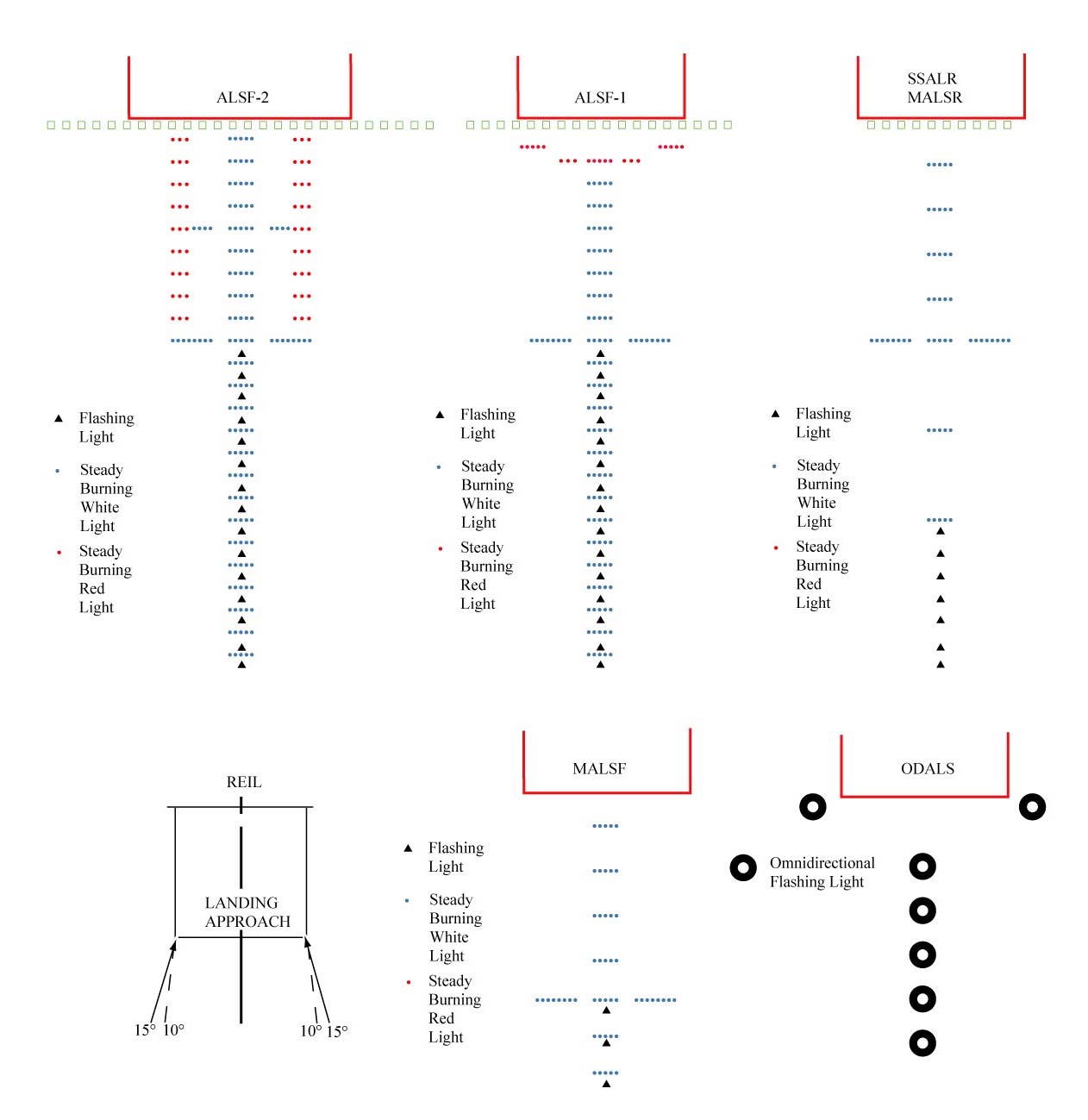
NOTE-
Civil ALSF-2 may be operated as SSALR during favorable weather conditions.
-
For 2-bar VASI (4 light units) see FIG 2-1-2.
FIG 2-1-2
2-Bar VASI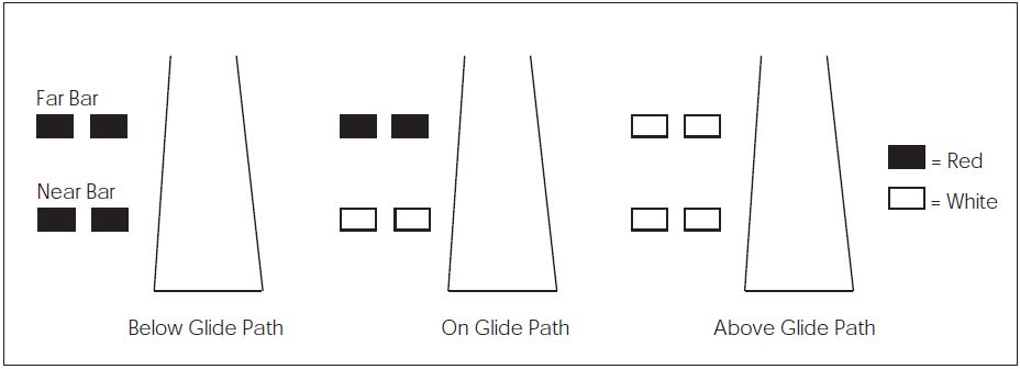
-
For 3-bar VASI (6 light units) see FIG 2-1-3.
FIG 2-1-3
3-Bar VASI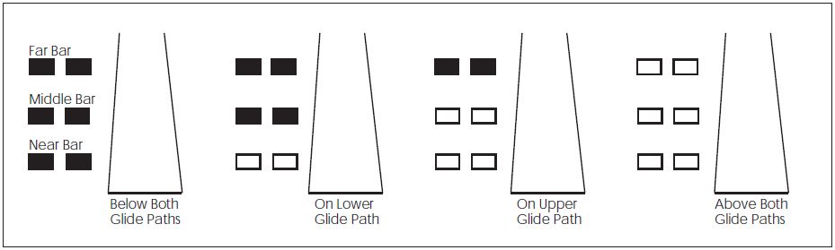
-
For other VASI configurations see FIG 2-1-4.
FIG 2-1-4
VASI Variations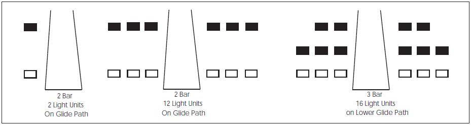
-
Precision Approach Path Indicator (PAPI).The precision approach path indicator (PAPI) uses light units similar to the VASI but are installed in a single row of either two or four light units. These lights are visible from about 5 miles during the day and up to 20 miles at night. The visual glide path of the PAPI typically provides safe obstruction clearance within plus or minus 10 degrees of the extended runway centerline and to 3.4 NM from the runway threshold. Descent, using the PAPI, should not be initiated until the aircraft is visually aligned with the runway. The row of light units is normally installed on the left side of the runway and the glide path indications are as depicted. Lateral course guidance is provided by the runway or runway lights. In certain circumstances, the safe obstruction clearance area may be reduced by narrowing the beam width or shortening the usable distance due to local limitations, or the PAPI may be offset from the extended runway centerline. This will be noted in the Chart Supplement and/or applicable NOTAMs. (See FIG 2-1-5.)
FIG 2-1-5
Precision Approach Path Indicator (PAPI)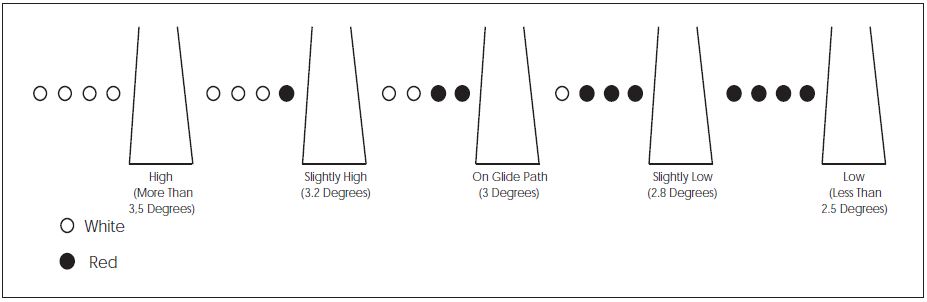
-
Tri-color Systems. Tri-color visual approach slope indicators normally consist of a single light unit projecting a three-color visual approach path into the final approach area of the runway upon which the indicator is installed. The below glide path indication is red, the above glide path indication is amber, and the on glide path indication is green. These types of indicators have a useful range of approximately one-half to one mile during the day and up to five miles at night depending upon the visibility conditions. (See FIG 2-1-6.)
FIG 2-1-6
Tri-Color Visual Approach Slope Indicator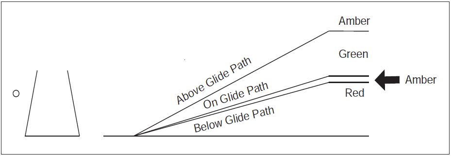
NOTE-
- Since the tri-color VASI consists of a single light source which could possibly be confused with other light sources, pilots should exercise care to properly locate and identify the light signal.
- When the aircraft descends from green to red, the pilot may see a dark amber color during the transition from green to red.
FIG 2-1-7
Pulsating Visual Approach Slope Indicator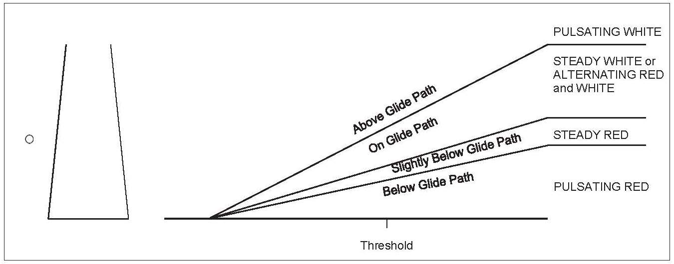
NOTE-
Since the PVASI consists of a single light source which could possibly be confused with other light sources, pilots should exercise care to properly locate and identify the light signal.
FIG 2-1-8
Alignment of Elements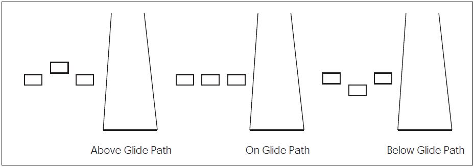
- Pulsating Systems. Pulsating visual approach slope indicators normally consist of a single light unit projecting a two-color visual approach path into the final approach area of the runway upon which the indicator is installed. The on glide path indication may be a steady white light or alternating RED and WHITE light. The slightly below glide path indication is a steady red light. If the aircraft descends further below the glide path, the red light starts to pulsate. The above glide path indication is a pulsating white light. The pulsating rate increases as the aircraft gets further above or below the desired glide slope. The useful range of the system is about four miles during the day and up to ten miles at night. (See FIG 2-1-7.)
- Alignment of Elements Systems. Alignment of elements systems are installed on some small general aviation airports and are a low-cost system consisting of painted plywood panels, normally black and white or fluorescent orange. Some of these systems are lighted for night use. The useful range of these systems is approximately three-quarter miles. To use the system the pilot positions the aircraft so the elements are in alignment. The glide path indications are shown in FIG 2-1-8.
-
Visual Approach Slope Indicator (VASI)
-
Runway End Identifier Lights (REIL)
REILs are installed at many airfields to provide rapid and positive identification of the approach end of a particular runway. The system consists of a pair of synchronized flashing lights located laterally on each side of the runway threshold. REILs may be either omnidirectional or unidirectional facing the approach area. They are effective for:
- Identification of a runway surrounded by a preponderance of other lighting.
- Identification of a runway which lacks contrast with surrounding terrain.
- Identification of a runway during reduced visibility.
-
Runway Edge Light Systems
- Runway edge lights are used to outline the edges of runways during periods of darkness or restricted visibility conditions. These light systems are classified according to the intensity or brightness they are capable of producing: they are the High Intensity Runway Lights (HIRL), Medium Intensity Runway Lights (MIRL), and the Low Intensity Runway Lights (LIRL). The HIRL and MIRL systems have variable intensity controls, whereas the LIRLs normally have one intensity setting.
- The runway edge lights are white, except on instrument runways yellow replaces white on the last 2,000 feet or half the runway length, whichever is less, to form a caution zone for landings.
- The lights marking the ends of the runway emit red light toward the runway to indicate the end of runway to a departing aircraft and emit green outward from the runway end to indicate the threshold to landing aircraft.
-
In-runway Lighting
- Runway Centerline Lighting System (RCLS). Runway centerline lights are installed on some precision approach runways to facilitate landing under adverse visibility conditions. They are located along the runway centerline and are spaced at 50-foot intervals. When viewed from the landing threshold, the runway centerline lights are white until the last 3,000 feet of the runway. The white lights begin to alternate with red for the next 2,000 feet, and for the last 1,000 feet of the runway, all centerline lights are red.
- Touchdown Zone Lights (TDZL). Touchdown zone lights are installed on some precision approach runways to indicate the touchdown zone when landing under adverse visibility conditions. They consist of two rows of transverse light bars disposed symmetrically about the runway centerline. The system consists of steady-burning white lights which start 100 feet beyond the landing threshold and extend to 3,000 feet beyond the landing threshold or to the midpoint of the runway, whichever is less.
- Taxiway Centerline Lead-Off Lights. Taxiway centerline lead-off lights provide visual guidance to persons exiting the runway. They are color-coded to warn pilots and vehicle drivers that they are within the runway environment or instrument landing system (ILS) critical area, whichever is more restrictive. Alternate green and yellow lights are installed, beginning with green, from the runway centerline to one centerline light position beyond the runway holding position or ILS critical area holding position.
- Taxiway Centerline Lead-On Lights. Taxiway centerline lead-on lights provide visual guidance to persons entering the runway. These “lead-on” lights are also color-coded with the same color pattern as lead-off lights to warn pilots and vehicle drivers that they are within the runway environment or instrument landing system (ILS) critical area, whichever is more conservative. The fixtures used for lead-on lights are bidirectional, i.e., one side emits light for the lead-on function while the other side emits light for the lead-off function. Any fixture that emits yellow light for the lead-off function must also emit yellow light for the lead-on function. (See FIG 2-1-12.)
-
Land and Hold Short Lights. Land and hold short lights are used to indicate the hold short point on certain runways which are approved for Land and Hold Short Operations (LAHSO). Land and hold short lights consist of a row of pulsing white lights installed across the runway at the hold short point. Where installed, the lights will be on anytime LAHSO is in effect. These lights will be off when LAHSO is not in effect.
REFERENCE-
AIM, Para 4-3-11, Pilot Responsibilities When Conducting Land and Hold Short Operations (LAHSO).
-
Runway Status Light (RWSL) System
- Introduction. RWSL is a fully automated system that provides runway status information to pilots and surface vehicle operators to clearly indicate when it is unsafe to enter, cross, takeoff from, or land on a runway. The RWSL system processes information from surveillance systems and activates Runway Entrance Lights (REL) and Takeoff Hold Lights (THL), in accordance with the position and velocity of the detected surface traffic and approach traffic. REL and THL are in-pavement light fixtures that are directly visible to pilots and surface vehicle operators. RWSL is an independent safety enhancement that does not substitute for or convey an ATC clearance. Clearance to enter, cross, takeoff from, land on, or operate on a runway must still be received from ATC. Although ATC has limited control over the system, personnel do not directly use and may not be able to view light fixture activations and deactivations during the conduct of daily ATC operations.
-
Runway Entrance Lights (REL): The REL system is composed of flush mounted, in-pavement, unidirectional light fixtures that are parallel to and focused along the taxiway centerline and directed toward the pilot at the hold line. An array of REL lights include the first light at the hold line followed by a series of evenly spaced lights to the runway edge; one additional light at the runway centerline is in line with the last two lights before the runway edge (see FIG 2-1-9 and FIG 2-1-10). When activated, the red lights indicate that there is high speed traffic on the runway or there is an aircraft on final approach within the activation area.
- REL Operating Characteristics - Departing Aircraft: When a departing aircraft reaches a site adaptable speed of approximately 30 knots, all taxiway intersections with REL arrays along the runway ahead of the aircraft will illuminate (see FIG 2-1-9). As the aircraft approaches an REL equipped taxiway intersection, the lights at that intersection extinguish approximately 3 to 4 seconds before the aircraft reaches it. This allows controllers to apply “anticipated separation" to permit ATC to move traffic more expeditiously without compromising safety. After the aircraft is declared “airborne" by the system, all REL lights associated with this runway will extinguish.
- REL Operating Characteristics - Arriving Aircraft: When an aircraft on final approach is approximately 1 mile from the runway threshold, all sets of taxiway REL light arrays that intersect the runway illuminate. The distance is adjustable and can be configured for specific operations at particular airports. Lights extinguish at each equipped taxiway intersection approximately 3 to 4 seconds before the aircraft reaches it to apply anticipated separation until the aircraft has slowed to approximately 80 knots (site adjustable parameter). Below 80 knots, all arrays that are not within 30 seconds of the aircraft's forward path are extinguished. Once the arriving aircraft slows to approximately 34 knots (site adjustable parameter), it is declared to be in a taxi state, and all lights extinguish.
- What a pilot would observe: A pilot at or approaching the hold line to a runway will observe RELs illuminate and extinguish in reaction to an aircraft or vehicle operating on the runway, or an arriving aircraft operating less than 1 mile from the runway threshold.
-
When a pilot observes the red lights of the REL, that pilot will stop at the hold line or remain stopped. The pilot will then contact ATC for resolution if the clearance is in conflict with the lights. Should pilots note illuminated lights under circumstances when remaining clear of the runway is impractical for safety reasons (for example, aircraft is already on the runway), the crew should proceed according to their best judgment while understanding the illuminated lights indicate the runway is unsafe to enter or cross. Contact ATC at the earliest possible opportunity.
FIG 2-1-9
Runway Status Light System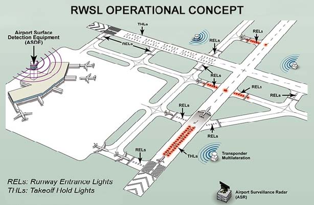
-
Takeoff Hold Lights (THL) : The THL system is composed of flush mounted, in-pavement, unidirectional light fixtures in a double longitudinal row aligned either side of the runway centerline lighting. Fixtures are focused toward the arrival end of the runway at the “line up and wait" point. THLs extend for 1,500 feet in front of the holding aircraft starting at a point 375 feet from the departure threshold (see FIG 2-1-11). Illuminated red lights provide a signal, to an aircraft in position for takeoff or rolling, that it is unsafe to takeoff because the runway is occupied or about to be occupied by another aircraft or ground vehicle. Two aircraft, or a surface vehicle and an aircraft, are required for the lights to illuminate. The departing aircraft must be in position for takeoff or beginning takeoff roll. Another aircraft or a surface vehicle must be on or about to cross the runway.
-
THL Operating Characteristics - Departing Aircraft: THLs will illuminate for an aircraft in position for departure or departing when there is another aircraft or vehicle on the runway or about to enter the runway (see FIG 2-1-9.) Once that aircraft or vehicle exits the runway, the THLs extinguish. A pilot may notice lights extinguish prior to the downfield aircraft or vehicle being completely clear of the runway but still moving. Like RELs, THLs have an “anticipated separation" feature.
NOTE-
When the THLs extinguish, this is not clearance to begin a takeoff roll. All takeoff clearances will be issued by ATC.
- What a pilot would observe: A pilot in position to depart from a runway, or has begun takeoff roll, will observe THLs illuminate in reaction to an aircraft or vehicle on the runway or entering or crossing it. Lights will extinguish when the runway is clear. A pilot may observe several cycles of illumination and extinguishing depending on the amount of crossing traffic.
- When a pilot observes the red light of the THLs, the pilot should safely stop if it's feasible or remain stopped. The pilot must contact ATC for resolution if any clearance is in conflict with the lights. Should pilots note illuminated lights while in takeoff roll and under circumstances when stopping is impractical for safety reasons, the crew should proceed according to their best judgment while understanding the illuminated lights indicate that continuing the takeoff is unsafe. Contact ATC at the earliest possible opportunity.
-
THL Operating Characteristics - Departing Aircraft: THLs will illuminate for an aircraft in position for departure or departing when there is another aircraft or vehicle on the runway or about to enter the runway (see FIG 2-1-9.) Once that aircraft or vehicle exits the runway, the THLs extinguish. A pilot may notice lights extinguish prior to the downfield aircraft or vehicle being completely clear of the runway but still moving. Like RELs, THLs have an “anticipated separation" feature.
-
Pilot Actions:
- When operating at airports with RWSL, pilots will operate with the transponder/ADS-B “On" when departing the gate or parking area until it is shut down upon arrival at the gate or parking area. This ensures interaction with the FAA surveillance systems such as ASDE-X/Airport Surface Surveillance Capability (ASSC) which provide information to the RWSL system.
- Pilots must always inform the ATCT when they have stoppeddue to an RWSL indication that is in conflict with ATC instructions. Pilots must request clarification of the taxi or takeoff clearance.
- Never cross over illuminated red lights. Under normal circumstances, RWSL will confirm the pilot's taxi or takeoff clearance previously issued by ATC. If RWSL indicates that it is unsafe to takeoff from, land on, cross, or enter a runway, immediately notify ATC of the conflict and re-confirm the clearance.
- Do not proceed when lights have extinguished without an ATC clearance. RWSL verifies an ATC clearance; it does not substitute for an ATC clearance.
-
ATC Control of RWSL System:
- Controllers can set in-pavement lights to one of five (5) brightness levels to assure maximum conspicuity under all visibility and lighting conditions. REL and THL subsystems may be independently set.
- System lights can be disabled should RWSL operations impact the efficient movement of air traffic or contribute, in the opinion of the assigned ATC Manager, to unsafe operations. REL and THL light fixtures may be disabled separately. Whenever the system or a component is disabled, a NOTAM must be issued, and the Automatic Terminal Information System (ATIS) must be updated.
-
Control of Lighting Systems
- Operation of approach light systems and runway lighting is controlled by the control tower (ATCT). At some locations the FSS may control the lights where there is no control tower in operation.
- Pilots may request that lights be turned on or off. Runway edge lights, in-pavement lights and approach lights also have intensity controls which may be varied to meet the pilots request. Sequenced flashing lights (SFL) may be turned on and off. Some sequenced flashing light systems also have intensity control.
-
Pilot Control of Airport Lighting
Radio control of lighting is available at selected airports to provide airborne control of lights by keying the aircraft's microphone. Control of lighting systems is often available at locations without specified hours for lighting and where there is no control tower or FSS or when the tower or FSS is closed (locations with a part-time tower or FSS) or specified hours. All lighting systems which are radio controlled at an airport, whether on a single runway or multiple runways, operate on the same radio frequency. (See TBL 2-1-1 and TBL 2-1-2.)
FIG 2-1-10
Runway Entrance Lights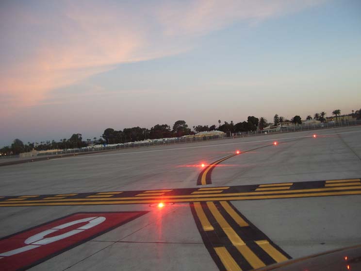
FIG 2-1-11
Takeoff Hold Lights
FIG 2-1-12
Taxiway Lead-On Light Configuration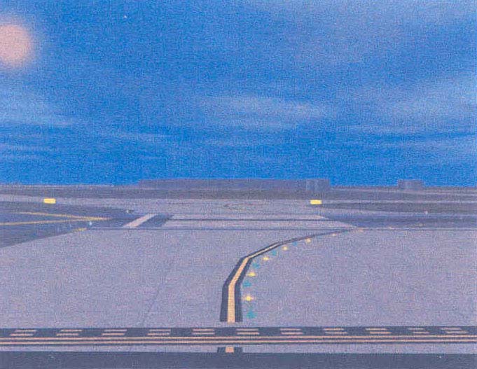
TBL 2-1-1
Runways With Approach LightsLighting System
No. of Int. Steps
Status During Nonuse Period
Intensity Step Selected Per No. of Mike Clicks
3 Clicks
5 Clicks
7 Clicks
Approach Lights (Med. Int.)
2
Off
Low
Low
High
Approach Lights (Med. Int.)
3
Off
Low
Med
High
MIRL
3
Off or Low
◆
◆
◆
HIRL
5
Off or Low
◆
◆
◆
VASI
2
Off
✬
✬
✬
NOTES:
◆ Predetermined intensity step.
✬ Low intensity for night use. High intensity for day use as determined by photocell control.TBL 2-1-2
Runways Without Approach LightsLighting System
No. of Int. Steps
Status During Nonuse Period
Intensity Step Selected Per No. of Mike Clicks
3 Clicks
5 Clicks
7 Clicks
MIRL
3
Off or Low
Low
Med.
High
HIRL
5
Off or Low
Step 1 or 2
Step 3
Step 5
LIRL
1
Off
On
On
On
VASI✬
2
Off
◆
◆
◆
REIL✬
1
Off
Off
On/Off
On
REIL✬
3
Off
Low
Med.
High
NOTES:
◆ Low intensity for night use. High intensity for day use as determined by photocell control.
✬ The control of VASI and/or REIL may be independent of other lighting systems.- With FAA approved systems, various combinations of medium intensity approach lights, runway lights, taxiway lights, VASI and/or REIL may be activated by radio control. On runways with both approach lighting and runway lighting (runway edge lights, taxiway lights, etc.) systems, the approach lighting system takes precedence for air-to-ground radio control over the runway lighting system which is set at a predetermined intensity step, based on expected visibility conditions. Runways without approach lighting may provide radio controlled intensity adjustments of runway edge lights. Other lighting systems, including VASI, REIL, and taxiway lights may be either controlled with the runway edge lights or controlled independently of the runway edge lights.
- The control system consists of a 3-step control responsive to 7, 5, and/or 3 microphone clicks. This 3-step control will turn on lighting facilities capable of either 3-step, 2-step or 1-step operation. The 3-step and 2-step lighting facilities can be altered in intensity, while the 1-step cannot. All lighting is illuminated for a period of 15 minutes from the most recent time of activation and may not be extinguished prior to end of the 15 minute period (except for 1-step and 2-step REILs which may be turned off when desired by keying the mike 5 or 3 times respectively).
-
Suggested use is to always initially key the mike 7 times; this assures that all controlled lights are turned on to the maximum available intensity. If desired, adjustment can then be made, where the capability is provided, to a lower intensity (or the REIL turned off) by keying 5 and/or 3 times. Due to the close proximity of airports using the same frequency, radio controlled lighting receivers may be set at a low sensitivity requiring the aircraft to be relatively close to activate the system. Consequently, even when lights are on, always key mike as directed when overflying an airport of intended landing or just prior to entering the final segment of an approach. This will assure the aircraft is close enough to activate the system and a full 15 minutes lighting duration is available. Approved lighting systems may be activated by keying the mike (within 5 seconds) as indicated in TBL 2-1-3.
TBL 2-1-3
Radio Control SystemKey Mike
Function
7 times within 5 seconds
Highest intensity available
5 times within 5 seconds
Medium or lower intensity (Lower REIL or REIL-off)
3 times within 5 seconds
Lowest intensity available (Lower REIL or REIL-off)
-
For all public use airports with FAA standard systems the Chart Supplement contains the types of lighting, runway and the frequency that is used to activate the system. Airports with IAPs include data on the approach chart identifying the light system, the runway on which they are installed, and the frequency that is used to activate the system.
NOTE-
Although the CTAF is used to activate the lights at many airports, other frequencies may also be used. The appropriate frequency for activating the lights on the airport is provided in the Chart Supplement and the standard instrument approach procedures publications. It is not identified on the sectional charts.
- Where the airport is not served by an IAP, it may have either the standard FAA approved control system or an independent type system of different specification installed by the airport sponsor. The Chart Supplement contains descriptions of pilot controlled lighting systems for each airport having other than FAA approved systems, and explains the type lights, method of control, and operating frequency in clear text.
-
Airport/Heliport Beacons
-
Airport and heliport beacons have a vertical light distribution to make them most effective from one to ten degrees above the horizon; however, they can be seen well above and below this peak spread. The beacon may be an omnidirectional capacitor-discharge device, or it may rotate at a constant speed which produces the visual effect of flashes at regular intervals. Flashes may be one or two colors alternately. The total number of flashes are:
- 24 to 30 per minute for beacons marking airports, landmarks, and points on Federal airways.
- 30 to 45 per minute for beacons marking heliports.
-
The colors and color combinations of beacons are:
- White and Green- Lighted land airport.
- *Green alone- Lighted land airport.
- White and Yellow- Lighted water airport.
- *Yellow alone- Lighted water airport.
-
Green, Yellow, and White- Lighted heliport.
NOTE-
*Green alone or yellow alone is used only in connection with a white-and-green or white-and-yellow beacon display, respectively.
- Military airport beacons flash alternately white and green, but are differentiated from civil beacons by dualpeaked (two quick) white flashes between the green flashes.
- In Class B, Class C, Class D and Class E surface areas, operation of the airport beacon during the hours of daylight often indicates that the ground visibility is less than 3 miles and/or the ceiling is less than 1,000 feet. ATC clearance in accordance with 14 CFR part 91 is required for landing, takeoff and flight in the traffic pattern. Pilots should not rely solely on the operation of the airport beacon to indicate if weather conditions are IFR or VFR. At some locations with operating control towers, ATC personnel turn the beacon on or off when controls are in the tower. At many airports the airport beacon is turned on by a photoelectric cell or time clocks and ATC personnel cannot control them. There is no regulatory requirement for daylight operation and it is the pilot's responsibility to comply with proper preflight planning as required by 14 CFR section 91.103.
-
Airport and heliport beacons have a vertical light distribution to make them most effective from one to ten degrees above the horizon; however, they can be seen well above and below this peak spread. The beacon may be an omnidirectional capacitor-discharge device, or it may rotate at a constant speed which produces the visual effect of flashes at regular intervals. Flashes may be one or two colors alternately. The total number of flashes are:
-
Taxiway Lights
-
Taxiway Edge Lights. Taxiway edge lights are used to outline the edges of taxiways during periods of darkness or restricted visibility conditions. These fixtures emit blue light.
NOTE-
At most major airports these lights have variable intensity settings and may be adjusted at pilot request or when deemed necessary by the controller.
- Taxiway Centerline Lights. Taxiway centerline lights are used to facilitate ground traffic under low visibility conditions. They are located along the taxiway centerline in a straight line on straight portions, on the centerline of curved portions, and along designated taxiing paths in portions of runways, ramp, and apron areas. Taxiway centerline lights are steady burning and emit green light.
- Clearance Bar Lights. Clearance bar lights are installed at holding positions on taxiways in order to increase the conspicuity of the holding position in low visibility conditions. They may also be installed to indicate the location of an intersecting taxiway during periods of darkness. Clearance bars consist of three in-pavement steady-burning yellow lights.
-
Runway Guard Lights. Runway guard lights are installed at taxiway/runway intersections. They are primarily used to enhance the conspicuity of taxiway/runway intersections during low visibility conditions, but may be used in all weather conditions. Runway guard lights consist of either a pair of elevated flashing yellow lights installed on either side of the taxiway, or a row of in-pavement yellow lights installed across the entire taxiway, at the runway holding position marking.
NOTE-
Some airports may have a row of three or five in-pavement yellow lights installed at taxiway/runway intersections. They should not be confused with clearance bar lights described in paragraph 2-1-10c, Clearance Bar Lights.
-
Stop Bar Lights. Stop bar lights, when installed, are used to confirm the ATC clearance to enter or cross the active runway in low visibility conditions (below 1,200 ft Runway Visual Range). A stop bar consists of a row of red, unidirectional, steady-burning in-pavement lights installed across the entire taxiway at the runway holding position, and elevated steady-burning red lights on each side. A controlled stop bar is operated in conjunction with the taxiway centerline lead-on lights which extend from the stop bar toward the runway. Following the ATC clearance to proceed, the stop bar is turned off and the lead-on lights are turned on. The stop bar and lead-on lights are automatically reset by a sensor or backup timer.
CAUTION-
Pilots should never cross a red illuminated stop bar, even if an ATC clearance has been given to proceed onto or across the runway.
NOTE-
If after crossing a stop bar, the taxiway centerline lead-on lights inadvertently extinguish, pilots should hold their position and contact ATC for further instructions.
-
Taxiway Edge Lights. Taxiway edge lights are used to outline the edges of taxiways during periods of darkness or restricted visibility conditions. These fixtures emit blue light.
Section 2. Air Navigation and Obstruction Lighting
-
Aeronautical Light Beacons
- An aeronautical light beacon is a visual NAVAID displaying flashes of white and/or colored light to indicate the location of an airport, a heliport, a landmark, a certain point of a Federal airway in mountainous terrain, or an obstruction. The light used may be a rotating beacon or one or more flashing lights. The flashing lights may be supplemented by steady burning lights of lesser intensity.
- The color or color combination displayed by a particular beacon and/or its auxiliary lights tell whether the beacon is indicating a landing place, landmark, point of the Federal airways, or an obstruction. Coded flashes of the auxiliary lights, if employed, further identify the beacon site.
-
Code Beacons and Course Lights
- Code Beacons. The code beacon, which can be seen from all directions, is used to identify airports and landmarks. The code beacon flashes the three or four character airport identifier in International Morse Code six to eight times per minute. Green flashes are displayed for land airports while yellow flashes indicate water airports.
-
Course Lights. The course light, which can be seen clearly from only one direction, is used only with rotating beacons of the Federal Airway System: two course lights, back to back, direct coded flashing beams of light in either direction along the course of airway.
NOTE-
Airway beacons are remnants of the “lighted” airways which antedated the present electronically equipped federal airways system. Only a few of these beacons exist today to mark airway segments in remote mountain areas. Flashes in Morse code identify the beacon site.
-
Obstruction Lights
-
Obstructions are marked/lighted to warn airmen of their presence during daytime and nighttime conditions. They may be marked/lighted in any of the following combinations:
- Aviation Red Obstruction Lights.Flashing aviation red beacons (20 to 40 flashes per minute) and steady burning aviation red lights during nighttime operation. Aviation orange and white paint is used for daytime marking.
- Medium Intensity Flashing White Obstruction Lights.Medium intensity flashing white obstruction lights may be used during daytime and twilight with automatically selected reduced intensity for nighttime operation. When this system is used on structures 500 feet (153m) AGL or less in height, other methods of marking and lighting the structure may be omitted. Aviation orange and white paint is always required for daytime marking on structures exceeding 500 feet (153m) AGL. This system is not normally installed on structures less than 200 feet (61m) AGL.
- High Intensity White Obstruction Lights.Flashing high intensity white lights during daytime with reduced intensity for twilight and nighttime operation. When this type system is used, the marking of structures with red obstruction lights and aviation orange and white paint may be omitted.
- Dual Lighting.A combination of flashing aviation red beacons and steady burning aviation red lights for nighttime operation and flashing high intensity white lights for daytime operation. Aviation orange and white paint may be omitted.
- Catenary Lighting.Lighted markers are available for increased night conspicuity of high-voltage (69KV or higher) transmission line catenary wires. Lighted markers provide conspicuity both day and night.
- Medium intensity omnidirectional flashing white lighting system provides conspicuity both day and night on catenary support structures. The unique sequential/simultaneous flashing light system alerts pilots of the associated catenary wires.
- High intensity flashing white lights are being used to identify some supporting structures of overhead transmission lines located across rivers, chasms, gorges, etc. These lights flash in a middle, top, lower light sequence at approximately 60 flashes per minute. The top light is normally installed near the top of the supporting structure, while the lower light indicates the approximate lower portion of the wire span. The lights are beamed towards the companion structure and identify the area of the wire span.
- High intensity flashing white lights are also employed to identify tall structures, such as chimneys and towers, as obstructions to air navigation. The lights provide a 360 degree coverage about the structure at 40 flashes per minute and consist of from one to seven levels of lights depending upon the height of the structure. Where more than one level is used the vertical banks flash simultaneously.
-
Obstructions are marked/lighted to warn airmen of their presence during daytime and nighttime conditions. They may be marked/lighted in any of the following combinations:
-
LED Lighting Systems
Certain light-emitting diode (LED) lighting systems fall outside the combined visible and near-infrared spectrum of night vision goggles (NVGs) and thus will not be visible to a flightcrew using NVGs.
The FAA changed specifications for LED-based red obstruction lights to make them visible to pilots using certain NVG systems, however, other colors may not be visible.
It is recommended that air carriers/operators—including part 91 operators—who use NVGs incorporate procedures into manuals and/or standard operating procedures (SOPs) requiring periodic, unaided scanning when operating at low altitudes and when performing a reconnaissance of landing areas.
Section 3. Airport Marking Aids and Signs
-
General
- Airport pavement markings and signs provide information that is useful to a pilot during takeoff, landing, and taxiing.
- Uniformity in airport markings and signs from one airport to another enhances safety and improves efficiency. Pilots are encouraged to work with the operators of the airports they use to achieve the marking and sign standards described in this section.
- Pilots who encounter ineffective, incorrect, or confusing markings or signs on an airport should make the operator of the airport aware of the problem. These situations may also be reported under the Aviation Safety Reporting Program as described in paragraph 7-7-1, Aviation Safety Reporting Program. Pilots may also report these situations to the FAA regional airports division.
-
The markings and signs described in this section of the AIM reflect the current FAA recommended standards.
REFERENCE-
AC 150/5340-1, Standards for Airport Markings.
AC 150/5340-18, Standards for Airport Sign Systems.
-
Airport Pavement Markings
-
General. For the purpose of this section, the airport pavement markings have been grouped into four areas:
- Runway Markings.
- Taxiway Markings.
- Holding Position Markings.
- Other Markings.
- Marking Colors. Markings for runways are white. Markings defining the landing area on a heliport are also white except for hospital heliports which use a red “H” on a white cross. Markings for taxiways, areas not intended for use by aircraft (closed and hazardous areas), and holding positions (even if they are on a runway) are yellow.
-
General. For the purpose of this section, the airport pavement markings have been grouped into four areas:
-
Runway Markings
-
General. There are three types of markings for runways: visual, nonprecision instrument, and precision instrument. TBL 2-3-1 identifies the marking elements for each type of runway and TBL 2-3-2 identifies runway threshold markings.
TBL 2-3-1
Runway Marking ElementsMarking Element
Visual Runway
Nonprecision Instrument Runway
Precision Instrument Runway
Designation
X
X
X
Centerline
X
X
X
Threshold
X1
X
X
Aiming Point
X2
X
X
Touchdown Zone
X
Side Stripes
X
1 On runways used, or intended to be used, by international commercial transports.
2 On runways 4,000 feet (1200 m) or longer used by jet aircraft.
FIG 2-3-1
Precision Instrument Runway Markings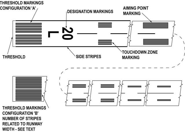
-
Runway Designators. Runway numbers and letters are determined from the approach direction. The runway number is the whole number nearest one‐tenth the magnetic azimuth of the centerline of the runway, measured clockwise from the magnetic north. The letters, differentiate between left (L), right (R), or center (C) parallel runways, as applicable:
- For two parallel runways “L” “R.”
- For three parallel runways “L” “C” “R.”
- Runway Centerline Marking. The runway centerline identifies the center of the runway and provides alignment guidance during takeoff and landings. The centerline consists of a line of uniformly spaced stripes and gaps.
- Runway Aiming Point Marking. The aiming point marking serves as a visual aiming point for a landing aircraft. These two rectangular markings consist of a broad white stripe located on each side of the runway centerline and approximately 1,000 feet from the landing threshold, as shown in FIG 2-3-1, Precision Instrument Runway Markings.
-
Runway Touchdown Zone Markers. The touchdown zone markings identify the touchdown zone for landing operations and are coded to provide distance information in 500 feet (150m) increments. These markings consist of groups of one, two, and three rectangular bars symmetrically arranged in pairs about the runway centerline, as shown in FIG 2-3-1. For runways having touchdown zone markings on both ends, those pairs of markings which extend to within 900 feet (270 m) of the midpoint between the thresholds are eliminated.
FIG 2-3-2
Nonprecision Instrument Runway and Visual Runway Markings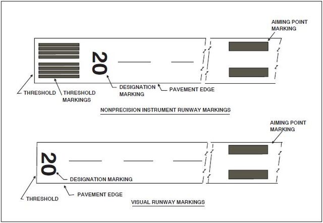
- Runway Side Stripe Marking. Runway side stripes delineate the edges of the runway. They provide a visual contrast between runway and the abutting terrain or shoulders. Side stripes consist of continuous white stripes located on each side of the runway as shown in FIG 2-3-4.
- Runway Shoulder Markings. Runway shoulder stripes may be used to supplement runway side stripes to identify pavement areas contiguous to the runway sides that are not intended for use by aircraft. Runway shoulder stripes are yellow. (See FIG 2-3-5.)
-
Runway Threshold Markings. Runway threshold markings come in two configurations. They either consist of eight longitudinal stripes of uniform dimensions disposed symmetrically about the runway centerline (as shown in FIG 2-3-1) or the number of stripes is related to the runway width as indicated in TBL 2-3-2. A threshold marking helps identify the beginning of the runway that is available for landing. In some instances, the landing threshold may be relocated or displaced.
TBL 2-3-2
Number of Runway Threshold StripesRunway Width
Number of Stripes
60 feet (18 m)
4
75 feet (23 m)
6
100 feet (30 m)
8
150 feet (45 m)
12
200 feet (60 m)
16
- Relocation of a Threshold.Sometimes construction, maintenance, or other activities require the threshold to be relocated towards the rollout end of the runway. (See FIG 2-3-3.) When a threshold is relocated, it closes not only a set portion of the approach end of a runway, but also shortens the length of the opposite direction runway. In these cases, a NOTAM should be issued by the airport operator identifying the portion of the runway that is closed (for example, 10/28 W 900 CLSD). Because the duration of the relocation can vary from a few hours to several months, methods identifying the new threshold may vary. One common practice is to use a ten feet wide white threshold bar across the width of the runway. Although the runway lights in the area between the old threshold and new threshold will not be illuminated, the runway markings in this area may or may not be obliterated, removed, or covered.
-
Displaced Threshold. A displaced threshold is a threshold located at a point on the runway other than the designated beginning of the runway. Displacement of a threshold reduces the length of runway available for landings. The portion of runway behind a displaced threshold is available for takeoffs in either direction and landings from the opposite direction. A ten feet wide white threshold bar is located across the width of the runway at the displaced threshold. White arrows are located along the centerline in the area between the beginning of the runway and displaced threshold. White arrow heads are located across the width of the runway just prior to the threshold bar, as shown in FIG 2-3-4.
NOTE-
Airport operator. When reporting the relocation or displacement of a threshold, the airport operator should avoid language which confuses the two.
-
Demarcation Bar. A demarcation bar delineates a runway with a displaced threshold from a blast pad, stopway, or taxiway that precedes the runway. A demarcation bar is 3 feet (1m) wide and yellow, since it is not located on the runway, as shown in FIG 2-3-6.
- Chevrons. These markings are used to show pavement areas aligned with the runway that are unusable for landing, takeoff, and taxiing. Chevrons are yellow. (See FIG 2-3-7.)
-
Runway Threshold Bar. A threshold bar delineates the beginning of the runway that is available for landing when the threshold has been relocated or displaced. A threshold bar is 10 feet (3m) in width and extends across the width of the runway, as shown in FIG 2-3-4.
FIG 2-3-3
Relocation of a Threshold with Markings for Taxiway Aligned with Runway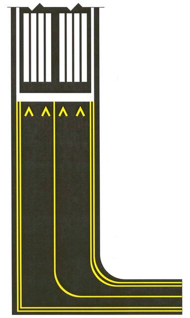
FIG 2-3-4
Displaced Threshold Markings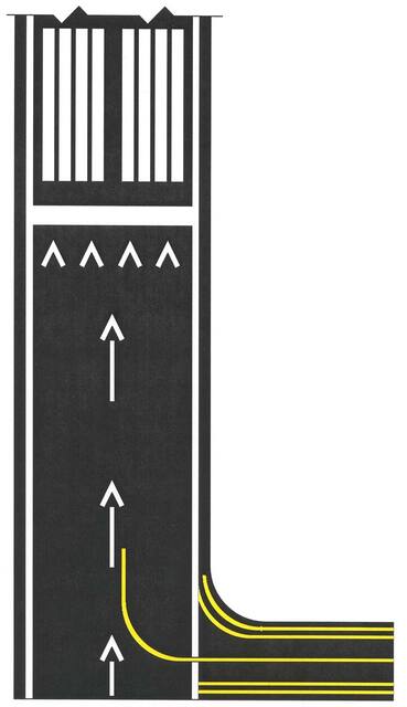
FIG 2-3-5
Runway Shoulder Markings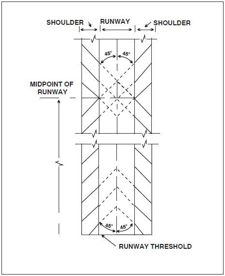
-
General. There are three types of markings for runways: visual, nonprecision instrument, and precision instrument. TBL 2-3-1 identifies the marking elements for each type of runway and TBL 2-3-2 identifies runway threshold markings.
-
Taxiway Markings
-
General. All taxiways should have centerline markings and runway holding position markings whenever they intersect a runway. Taxiway edge markings are present whenever there is a need to separate the taxiway from a pavement that is not intended for aircraft use or to delineate the edge of the taxiway. Taxiways may also have shoulder markings and holding position markings for Instrument Landing System (ILS) critical areas and taxiway/taxiway intersection markings.
REFERENCE-
AIM, Para 2-3-5, Holding Position Markings.
-
Taxiway Centerline.
- Normal Centerline. The taxiway centerline is a single continuous yellow line, 6 inches (15 cm) to 12 inches (30 cm) in width. This provides a visual cue to permit taxiing along a designated path. Ideally, the aircraft should be kept centered over this line during taxi. However, being centered on the taxiway centerline does not guarantee wingtip clearance with other aircraft or other objects.
- Enhanced Centerline. At some airports, mostly the larger commercial service airports, an enhanced taxiway centerline will be used. The enhanced taxiway centerline marking consists of a parallel line of yellow dashes on either side of the normal taxiway centerline. The taxiway centerlines are enhanced for a maximum of 150 feet prior to a runway holding position marking. The purpose of this enhancement is to warn the pilot that he/she is approaching a runway holding position marking and should prepare to stop unless he/she has been cleared onto or across the runway by ATC. (See FIG 2-3-8.)
-
Taxiway Edge Markings. Taxiway edge markings are used to define the edge of the taxiway. They are primarily used when the taxiway edge does not correspond with the edge of the pavement. There are two types of markings depending upon whether the aircraft is supposed to cross the taxiway edge:
- Continuous Markings.These consist of a continuous double yellow line, with each line being at least 6 inches (15 cm) in width spaced 6 inches (15 cm) apart. They are used to define the taxiway edge from the shoulder or some other abutting paved surface not intended for use by aircraft.
- Dashed Markings. These markings are used when there is an operational need to define the edge of a taxiway or taxilane on a paved surface where the adjoining pavement to the taxiway edge is intended for use by aircraft (for example, an apron). Dashed taxiway edge markings consist of a broken double yellow line, with each line being at least 6 inches (15 cm) in width, spaced 6 inches (15 cm) apart (edge to edge). These lines are 15 feet (4.5 m) in length with 25 foot (7.5 m) gaps. (See FIG 2-3-9.)
-
Taxi Shoulder Markings. Taxiways, holding bays, and aprons are sometimes provided with paved shoulders to prevent blast and water erosion. Although shoulders may have the appearance of full strength pavement, they are not intended for use by aircraft and may be unable to support an aircraft. Usually the taxiway edge marking will define this area. Where conditions exist such as islands or taxiway curves that may cause confusion as to which side of the edge stripe is for use by aircraft, taxiway shoulder markings may be used to indicate the pavement is unusable. Taxiway shoulder markings are yellow. (See FIG 2-3-10.)
FIG 2-3-6
Markings for Blast Pad or Stopway or Taxiway Preceding a Displaced Threshold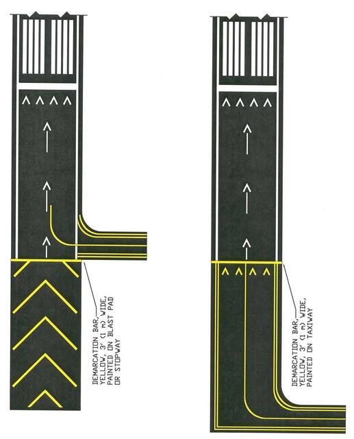
FIG 2-3-7
Markings for Blast Pads and Stopways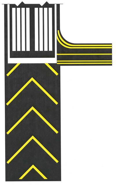
FIG 2-3-8
Enhanced Taxiway Centerline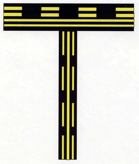
FIG 2-3-9
Dashed Markings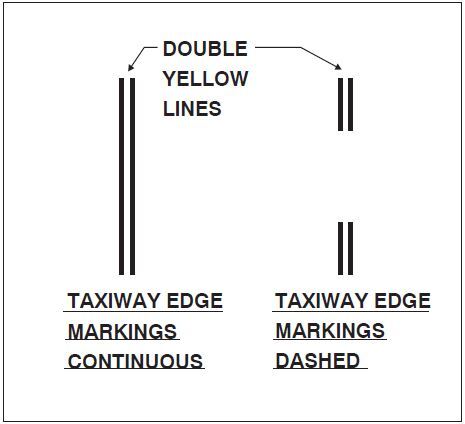
-
Surface Painted Taxiway Direction Signs. Surface painted taxiway direction signs have a yellow background with a black inscription, and are provided when it is not possible to provide taxiway direction signs at intersections, or when necessary to supplement such signs. These markings are located adjacent to the centerline with signs indicating turns to the left being on the left side of the taxiway centerline, and signs indicating turns to the right being on the right side of the centerline. (See FIG 2-3-11.)
FIG 2-3-10
Taxi Shoulder Markings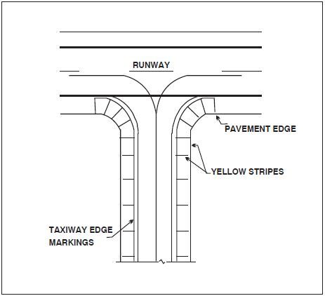
- Surface Painted Location Signs. Surface painted location signs have a black background with a yellow inscription. When necessary, these markings are used to supplement location signs located along side the taxiway and assist the pilot in confirming the designation of the taxiway on which the aircraft is located. These markings are located on the right side of the centerline. (See FIG 2-3-11.)
-
Geographic Position Markings. These markings are located at points along low visibility taxi routes designated in the airport's Surface Movement Guidance Control System (SMGCS) plan. They are used to identify the location of taxiing aircraft during low visibility operations. Low visibility operations are those that occur when the runway visible range (RVR) is below 1200 feet (360m). They are positioned to the left of the taxiway centerline in the direction of taxiing. (See FIG 2-3-12.) The geographic position marking is a circle comprised of an outer black ring contiguous to a white ring with a pink circle in the middle. When installed on asphalt or other dark‐colored pavements, the white ring and the black ring are reversed (i.e., the white ring becomes the outer ring and the black ring becomes the inner ring). It is designated with either a number or a number and letter. The number corresponds to the consecutive position of the marking on the route.
FIG 2-3-11
Surface Painted Signs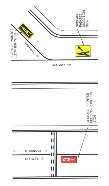
-
General. All taxiways should have centerline markings and runway holding position markings whenever they intersect a runway. Taxiway edge markings are present whenever there is a need to separate the taxiway from a pavement that is not intended for aircraft use or to delineate the edge of the taxiway. Taxiways may also have shoulder markings and holding position markings for Instrument Landing System (ILS) critical areas and taxiway/taxiway intersection markings.
-
Holding Position Markings
-
Runway Holding Position Markings. For runways, these markings indicate where aircraft MUST STOP when approaching a runway. They consist of four yellow lines, two solid and two dashed, spaced six or twelve inches apart, and extending across the width of the taxiway or runway. The solid lines are always on the side where the aircraft must hold. There are three locations where runway holding position markings are encountered.
-
Runway Holding Position Markings on Taxiways. These markings identify the locations on a taxiway where aircraft MUST STOP when a clearance has not been issued to proceed onto the runway. Generally, runway holding position markings also identify the boundary of the runway safety area (RSA) for aircraft exiting the runway. Runway holding position markings are shown in FIG 2-3-13 and FIG 2-3-16. When instructed by ATC, “Hold short of Runway XX,” the pilot MUST STOP so that no part of the aircraft extends beyond the runway holding position marking. When approaching runways at airports with an operating control tower, pilots must not cross the runway holding position marking without ATC clearance. Pilots approaching runways at airports without an operating control tower must ensure adequate separation from other aircraft, vehicles, and pedestrians prior to crossing the holding position markings. An aircraft exiting a runway is not clear of the runway until all parts of the aircraft have crossed the applicable holding position marking.
NOTE-
Runway holding position markings identify the beginning of an RSA, and a pilot MUST STOP to get clearance before crossing (at airports with operating control towers).
REFERENCE-
AIM, Para 4-3-21, Exiting the Runway After Landing.
- Runway Holding Position Markings on Runways.These markings identify the locations on runways where aircraft MUST STOP. These markings are located on runways used by ATC for Land And Hold Short Operations (for example, see FIG 4-3-8) and Taxiing operations. For taxiing operations, the pilot MUST STOP prior to the holding position markings unless explicitly authorized to cross by ATC. A sign with a white inscription on a red background is located adjacent to these holding position markings. (See FIG 2-3-14.) The holding position markings are placed on runways prior to the intersection with another runway, or some designated point. Pilots receiving and accepting instructions “Cleared to land Runway XX, hold short of Runway YY” from ATC must either exit Runway XX prior to the holding position markings, or stop at the holding position markings prior to Runway YY. Otherwise, pilots are authorized to use the entire landing length of the runway and disregard the holding position markings.
- Holding Position Markings on Taxiways Located in Runway Approach Areas.These markings are used at some airports where it is necessary to hold an aircraft on a taxiway located in the approach or departure area of a runway so that the aircraft does not interfere with the operations on that runway. This marking is collocated with the runway approach/departure area holding position sign. When specifically instructed by ATC, “Hold short of Runway XX approach or Runway XX departure area,” the pilot MUST STOP so that no part of the aircraft extends beyond the holding position marking. (See Subparagraph 2-3-8b2, Runway Approach Area Holding Position Sign, and FIG 2-3-15.)
-
Runway Holding Position Markings on Taxiways. These markings identify the locations on a taxiway where aircraft MUST STOP when a clearance has not been issued to proceed onto the runway. Generally, runway holding position markings also identify the boundary of the runway safety area (RSA) for aircraft exiting the runway. Runway holding position markings are shown in FIG 2-3-13 and FIG 2-3-16. When instructed by ATC, “Hold short of Runway XX,” the pilot MUST STOP so that no part of the aircraft extends beyond the runway holding position marking. When approaching runways at airports with an operating control tower, pilots must not cross the runway holding position marking without ATC clearance. Pilots approaching runways at airports without an operating control tower must ensure adequate separation from other aircraft, vehicles, and pedestrians prior to crossing the holding position markings. An aircraft exiting a runway is not clear of the runway until all parts of the aircraft have crossed the applicable holding position marking.
-
Holding Position Markings for Instrument Landing System (ILS). Holding position markings for ILS critical areas consist of two yellow solid lines spaced two feet apart connected by pairs of solid lines spaced ten feet apart extending across the width of the taxiway as shown. (See FIG 2-3-16.) A sign with an inscription in white on a red background is located adjacent to these hold position markings. When instructed by ATC to hold short of the ILS critical area, pilots MUST STOP so that no part of the aircraft extends beyond the holding position marking. When approaching the holding position marking, pilots must not cross the marking without ATC clearance. The ILS critical area is not clear until all parts of the aircraft have crossed the applicable holding position marking.
REFERENCE-
AIM, Para 1-1-9, Instrument Landing System (ILS).
- Holding Position Markings for Intersecting Taxiways Holding position markings for intersecting taxiways consist of a single dashed line extending across the width of the taxiway as shown. (See FIG 2-3-17.) They are located on taxiways where ATC holds aircraft short of a taxiway intersection. When instructed by ATC, “Hold short of Taxiway XX,” the pilot MUST STOP so that no part of the aircraft extends beyond the holding position marking. When the marking is not present, the pilot MUST STOP the aircraft at a point which provides adequate clearance from an aircraft on the intersecting taxiway.
-
Surface Painted Holding Position Signs. Surface painted holding position signs have a red background with a white inscription and supplement the signs located at the holding position. This type of marking is normally used where the width of the holding position on the taxiway is greater than 200 feet (60 m). It is located to the left side of the taxiway centerline on the holding side and prior to the holding position marking. (See FIG 2-3-11.)
FIG 2-3-12
Geographic Position Markings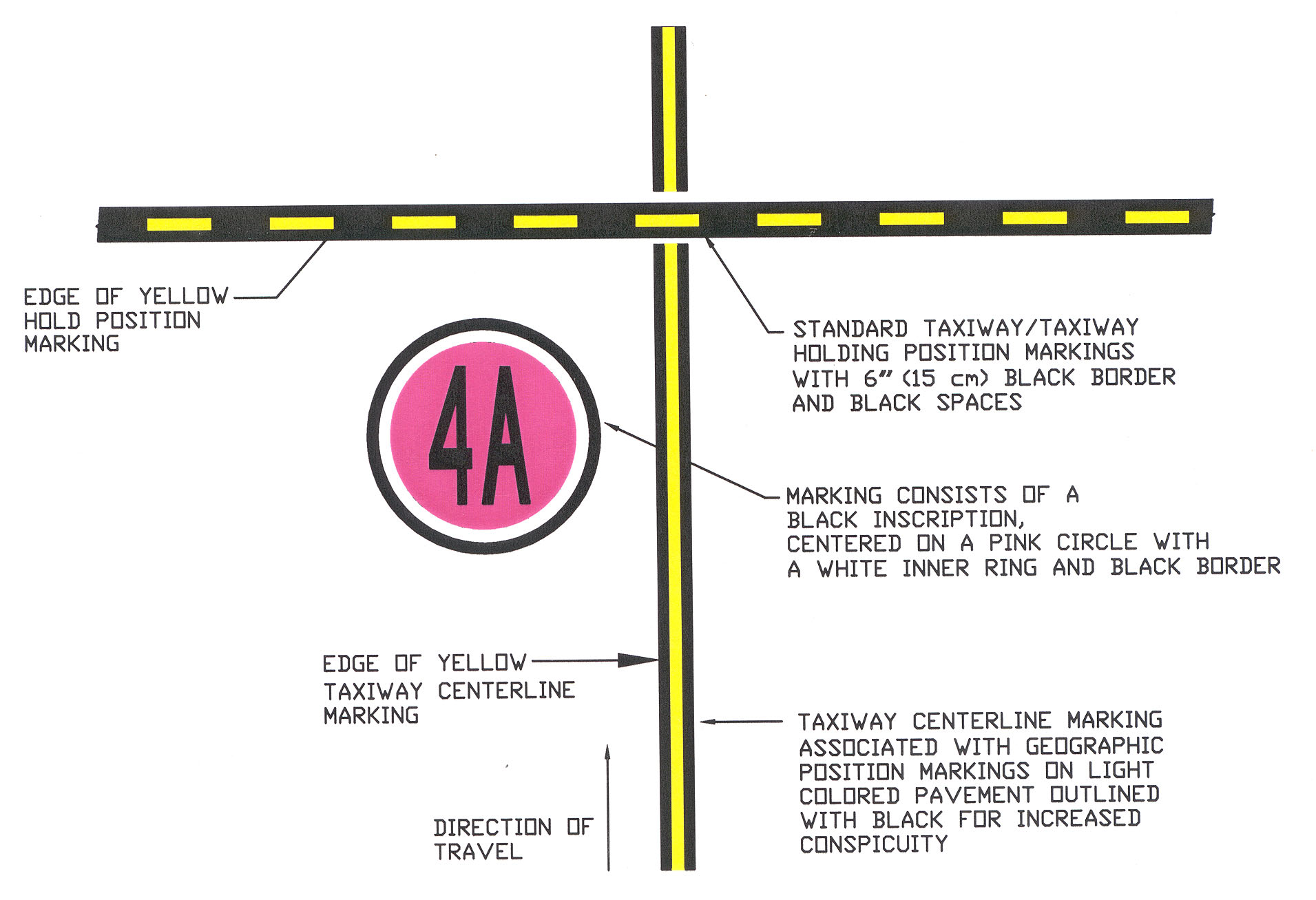
FIG 2-3-13
Runway Holding Position Markings on Taxiway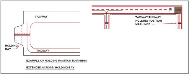
FIG 2-3-14
Runway Holding Position Markings on Runways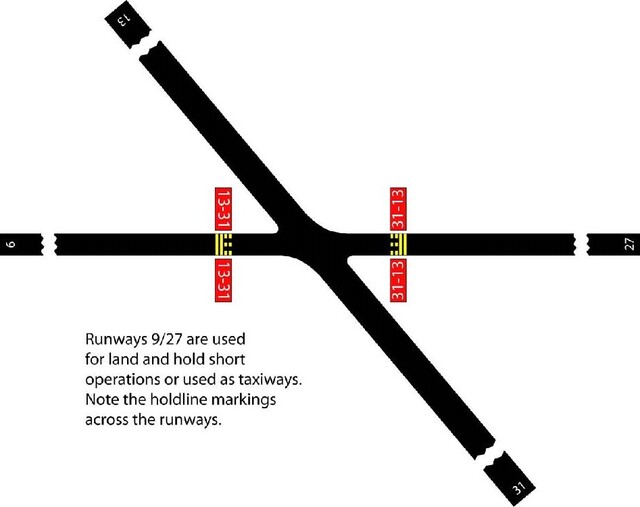
FIG 2-3-15
Taxiways Located in Runway Approach and Departure Areas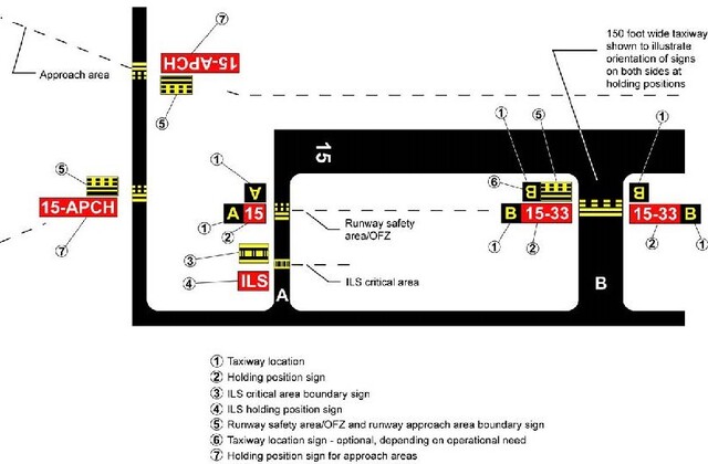
NOTE-
- Refer to Advisory Circular 150/5300-13 for additional information on obstruction surfaces.
- Because Taxiway C does not enter the departure area of Runway 33, the sign on Taxiway C does not include the “33 DEP” legend.
- The location of a holding position is relative to the point on the aircraft that infringes the surface; for inclining surfaces such as an approach surface, the location of the holdline position may differ from the location of the infringement point.
FIG 2-3-16
Holding Position Markings: ILS Critical Area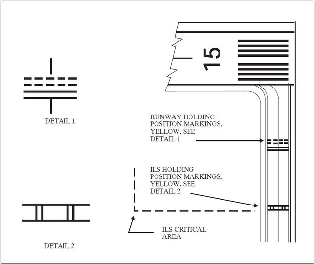
-
Runway Holding Position Markings. For runways, these markings indicate where aircraft MUST STOP when approaching a runway. They consist of four yellow lines, two solid and two dashed, spaced six or twelve inches apart, and extending across the width of the taxiway or runway. The solid lines are always on the side where the aircraft must hold. There are three locations where runway holding position markings are encountered.
-
Other Markings
- Vehicle Roadway Markings. The vehicle roadway markings are used when necessary to define a pathway for vehicle operations on or crossing areas that are also intended for aircraft. These markings consist of a white solid line to delineate each edge of the roadway and a dashed line to separate lanes within the edges of the roadway. In lieu of the solid lines, zipper markings may be used to delineate the edges of the vehicle roadway. (See FIG 2-3-18.) Details of the zipper markings are shown in FIG 2-3-19.
-
VOR Receiver Checkpoint Markings. The VOR receiver checkpoint marking allows the pilot to check aircraft instruments with navigational aid signals. It consists of a painted circle with an arrow in the middle; the arrow is aligned in the direction of the checkpoint azimuth. This marking, and an associated sign, is located on the airport apron or taxiway at a point selected for easy access by aircraft but where other airport traffic is not to be unduly obstructed. (See FIG 2-3-20.)
NOTE-
The associated sign contains the VOR station identification letter and course selected (published) for the check, the words “VOR check course,” and DME data (when applicable). The color of the letters and numerals are black on a yellow background.
EXAMPLE-
DCA 176-356
VOR check course
DME XXXFIG 2-3-17
Holding Position Markings: Taxiway/Taxiway Intersections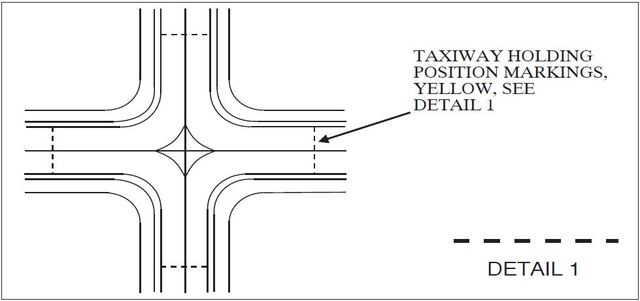
FIG 2-3-18
Vehicle Roadway Markings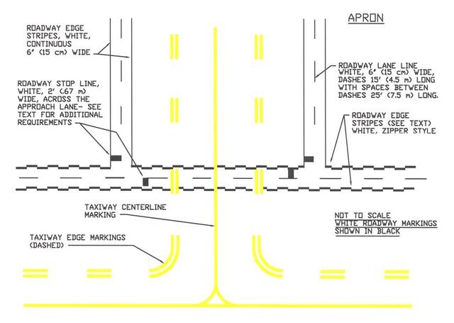
FIG 2-3-19
Roadway Edge Stripes, White, Zipper Style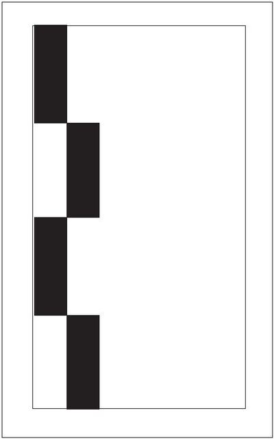
-
Nonmovement Area Boundary Markings. These markings delineate the movement area (i.e., area under ATC). These markings are yellow and located on the boundary between the movement and nonmovement area. The nonmovement area boundary markings consist of two yellow lines (one solid and one dashed) 6 inches (15cm) in width. The solid line is located on the nonmovement area side, while the dashed yellow line is located on the movement area side. The nonmovement boundary marking area is shown in FIG 2-3-21.
FIG 2-3-20
Ground Receiver Checkpoint Markings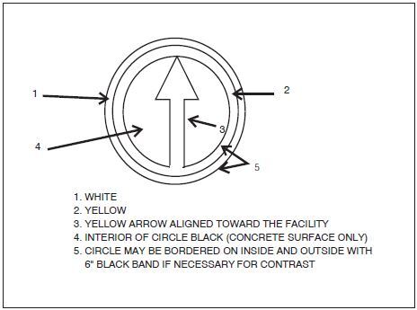
FIG 2-3-21
Nonmovement Area Boundary Markings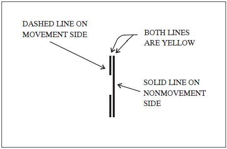
FIG 2-3-22
Closed or Temporarily Closed Runway and Taxiway Markings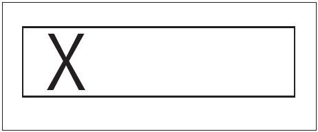
-
Marking and Lighting of Permanently Closed Runways and Taxiways. For runways and taxiways which are permanently closed, the lighting circuits will be disconnected. The runway threshold, runway designation, and touchdown markings are obliterated and yellow crosses are placed at each end of the runway and at 1,000 foot intervals. (See FIG 2-3-22.)
FIG 2-3-23
Helicopter Landing Areas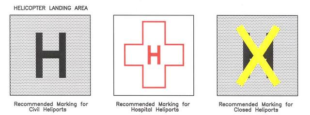
-
Temporarily Closed Runways and Taxiways.To provide a visual indication to pilots that a runway is temporarily closed, crosses are placed on the runway only at each end of the runway. The crosses are yellow in color. (See FIG 2-3-22.)
- A raised lighted yellow cross may be placed on each runway end in lieu of the markings described in Subparagraph e, Temporarily Closed Runways and Taxiways, to indicate the runway is closed.
- A visual indication may not be present depending on the reason for the closure, duration of the closure, airfield configuration, and the existence and the hours of operation of an airport traffic control tower. Pilots should check NOTAMs and the Automated Terminal Information System (ATIS) for local runway and taxiway closure information.
- Temporarily closed taxiways are usually treated as hazardous areas, in which no part of an aircraft may enter, and are blocked with barricades. However, as an alternative, a yellow cross may be installed at each entrance to the taxiway.
- Helicopter Landing Areas.The markings illustrated in FIG 2-3-23 are used to identify the landing and takeoff area at a public use heliport and hospital heliport. The letter “H” in the markings is oriented to align with the intended direction of approach. FIG 2-3-23 also depicts the markings for a closed airport.
-
Airport Signs
There are six types of signs installed on airfields: mandatory instruction signs, location signs, direction signs, destination signs, information signs, and runway distance remaining signs. The characteristics and use of these signs are discussed in paragraph 2-3-8, Mandatory Instruction Signs, through paragraph 2-3-13, Runway Distance Remaining Signs.
REFERENCE-
AC150/5340-18, Standards for Airport Sign Systems for Detailed Information on Airport Signs.
FIG 2-3-24
Runway Holding Position Sign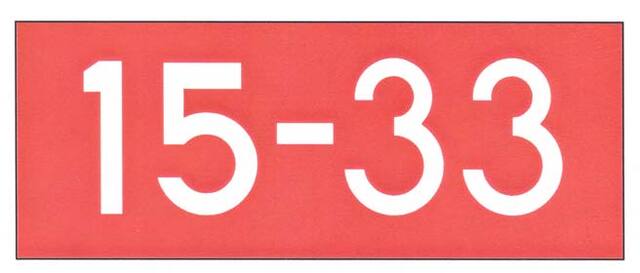
FIG 2-3-25
Holding Position Sign at Beginning of Takeoff Runway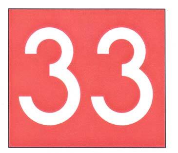
-
Mandatory Instruction Signs
-
These signs have a red background with a white inscription and are used to denote:
- An entrance to a runway or critical area; and
- Areas where an aircraft is prohibited from entering.
-
Typical mandatory signs and applications are:
-
Runway Holding Position Sign. This sign is located at the holding position on taxiways that intersect a runway or on runways that intersect other runways. The inscription on the sign contains the designation of the intersecting runway, as shown in FIG 2-3-24. The runway numbers on the sign are arranged to correspond to the respective runway threshold. For example, “15-33” indicates that the threshold for Runway 15 is to the left and the threshold for Runway 33 is to the right.
-
On taxiways that intersect the beginning of the takeoff runway, only the designation of the takeoff runway may appear on the sign (as shown in FIG 2-3-25), while all other signs will have the designation of both runway directions.
FIG 2-3-26
Holding Position Sign for a Taxiway that Intersects the Intersection of Two Runways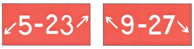
FIG 2-3-27
Holding Position Sign for Runway Approach and Departure Areas
- If the sign is located on a taxiway that intersects the intersection of two runways, the designations for both runways will be shown on the sign along with arrows showing the approximate alignment of each runway, as shown in FIG 2-3-26. In addition to showing the approximate runway alignment, the arrow indicates the direction to the threshold of the runway whose designation is immediately next to the arrow.
- A runway holding position sign on a taxiway will be installed adjacent to holding position markings on the taxiway pavement. On runways, holding position markings will be located only on the runway pavement adjacent to the sign, if the runway is normally used by ATC for “Land, Hold Short” operations or as a taxiway. The holding position markings are described in paragraph 2-3-5, Holding Position Markings.
-
On taxiways that intersect the beginning of the takeoff runway, only the designation of the takeoff runway may appear on the sign (as shown in FIG 2-3-25), while all other signs will have the designation of both runway directions.
-
Runway Approach Area Holding Position Sign. At some airports, it is necessary to hold an aircraft on a taxiway located in the approach or departure area for a runway so that the aircraft does not interfere with operations on that runway. FIG 2-3-15 depicts common situations. A sign with the runway designation(s) and the protected area(s) will be located at applicable holding positions on the taxiway. For locations protecting only the approach area, the holding position on the taxiway includes a sign identifying the approach end runway designation (e.g., 15) followed by a dash (-) and the letters “APCH”. For locations protecting both the approach and departure areas, the holding position on the taxiway includes a sign with the approach end runway designation and letters “APCH” followed by a dash (-), the departure end runway designation and the letters “DEP”. The arrangement of the runway designations and protected areas legend on the sign reflects the orientation of the runway as viewed from the holding position. Holding position markings in accordance with paragraph 2-3-5, Holding Position Markings, are co-located on the taxiway pavement in line with the sign. Examples of these signs are shown in FIG 2-3-27.
FIG 2-3-28
Holding Position Sign for ILS Critical Area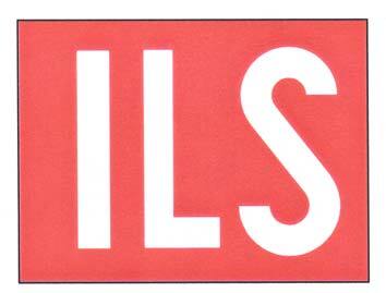
FIG 2-3-29
Sign Prohibiting Aircraft Entry into an Area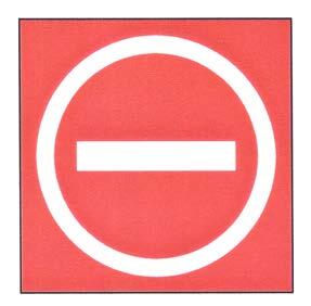
- ILS Critical Area Holding Position Sign.At some airports, when the instrument landing system is being used, it is necessary to hold an aircraft on a taxiway at a location other than the holding position described in Paragraph 2-3-5, Holding Position Markings. In these situations, the holding position sign for these operations will have the inscription “ILS” and be located adjacent to the holding position marking on the taxiway described in paragraph 2-3-5. An example of this sign is shown in FIG 2-3-28.
-
No Entry Sign.This sign, shown in FIG 2-3-29, prohibits an aircraft from entering an area. Typically, this sign would be located on a taxiway intended to be used in only one direction or at the intersection of vehicle roadways with runways, taxiways, or aprons where the roadway may be mistaken as a taxiway or other aircraft movement surface.
NOTE-
Holding position signs provide the pilot with a visual cue as to the location of the holding position marking.
REFERENCE-
AIM, Para 2-3-5, Holding Position Markings.
FIG 2-3-30
Taxiway Location Sign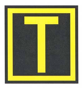
FIG 2-3-31
Taxiway Location Sign Collocated with Runway Holding Position Sign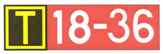
-
Runway Holding Position Sign. This sign is located at the holding position on taxiways that intersect a runway or on runways that intersect other runways. The inscription on the sign contains the designation of the intersecting runway, as shown in FIG 2-3-24. The runway numbers on the sign are arranged to correspond to the respective runway threshold. For example, “15-33” indicates that the threshold for Runway 15 is to the left and the threshold for Runway 33 is to the right.
-
These signs have a red background with a white inscription and are used to denote:
-
Location Signs
-
Location signs are used to identify either a taxiway or runway on which the aircraft is located. Other location signs provide a visual cue to pilots to assist them in determining when they have exited an area. The various location signs are described below.
-
Taxiway Location Sign.This sign has a black background with a yellow inscription and yellow border, as shown in FIG 2-3-30. The inscription is the designation of the taxiway on which the aircraft is located. These signs are installed along taxiways either by themselves or in conjunction with direction signs or runway holding position signs. (See FIG 2-3-35 and FIG 2-3-31.)
FIG 2-3-32
Runway Location Sign
FIG 2-3-33
Runway Boundary Sign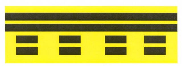
- Runway Location Sign.This sign has a black background with a yellow inscription and yellow border, as shown in FIG 2-3-32. The inscription is the designation of the runway on which the aircraft is located. These signs are intended to complement the information available to pilots through their magnetic compass and typically are installed where the proximity of two or more runways to one another could cause pilots to be confused as to which runway they are on.
-
Runway Boundary Sign.This sign has a yellow background with a black inscription with a graphic depicting the pavement holding position marking, as shown in FIG 2-3-33. This sign, which faces the runway and is visible to the pilot exiting the runway, is located adjacent to the holding position marking on the pavement. The sign is intended to provide pilots with another visual cue which they can use as a guide in deciding when they are “clear of the runway.”
FIG 2-3-34
ILS Critical Area Boundary Sign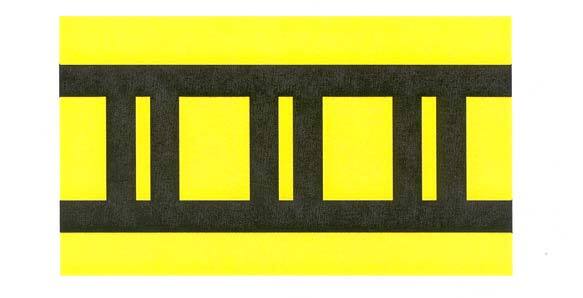
- ILS Critical Area Boundary Sign. This sign has a yellow background with a black inscription with a graphic depicting the ILS pavement holding position marking as shown in FIG 2-3-34. This sign is located adjacent to the ILS holding position marking on the pavement and can be seen by pilots leaving the critical area. The sign is intended to provide pilots with another visual cue which they can use as a guide in deciding when they are “clear of the ILS critical area.”
-
Taxiway Location Sign.This sign has a black background with a yellow inscription and yellow border, as shown in FIG 2-3-30. The inscription is the designation of the taxiway on which the aircraft is located. These signs are installed along taxiways either by themselves or in conjunction with direction signs or runway holding position signs. (See FIG 2-3-35 and FIG 2-3-31.)
-
Location signs are used to identify either a taxiway or runway on which the aircraft is located. Other location signs provide a visual cue to pilots to assist them in determining when they have exited an area. The various location signs are described below.
-
Direction Signs
- Direction signs have a yellow background with a black inscription. The inscription identifies the designation(s) of the intersecting taxiway(s) leading out of the intersection that a pilot would normally be expected to turn onto or hold short of. Each designation is accompanied by an arrow indicating the direction of the turn.
- Except as noted in subparagraph e, each taxiway designation shown on the sign is accompanied by only one arrow. When more than one taxiway designation is shown on the sign, each designation and its associated arrow is separated from the other taxiway designations by either a vertical message divider or a taxiway location sign as shown in FIG 2-3-35.
- Direction signs are normally located on the left prior to the intersection. When used on a runway to indicate an exit, the sign is located on the same side of the runway as the exit. FIG 2-3-36 shows a direction sign used to indicate a runway exit.
- The taxiway designations and their associated arrows on the sign are arranged clockwise starting from the first taxiway on the pilot's left. (See FIG 2-3-35.)
- If a location sign is located with the direction signs, it is placed so that the designations for all turns to the left will be to the left of the location sign; the designations for continuing straight ahead or for all turns to the right would be located to the right of the location sign. (See FIG 2-3-35.)
-
When the intersection is comprised of only one crossing taxiway, it is permissible to have two arrows associated with the crossing taxiway, as shown in FIG 2-3-37. In this case, the location sign is located to the left of the direction sign.
FIG 2-3-35
Direction Sign Array with Location Sign on Far Side of Intersection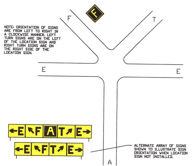
FIG 2-3-36
Direction Sign for Runway Exit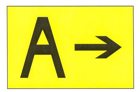
FIG 2-3-37
Direction Sign Array for Simple Intersection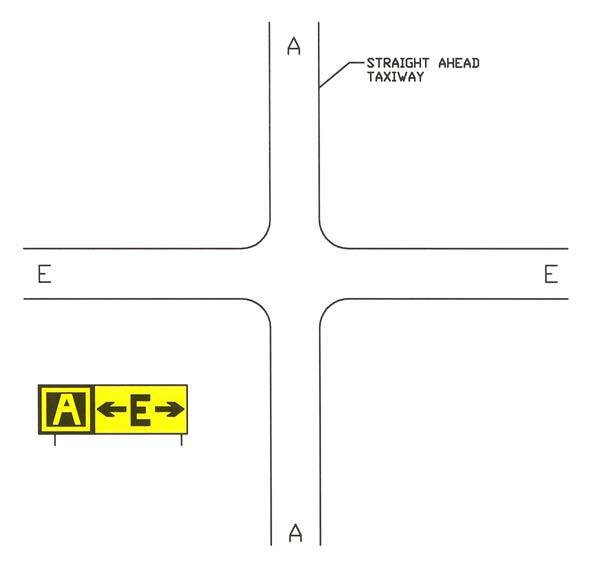
-
Destination Signs
- Destination signs have a yellow background with a black inscription indicating a taxi route to a destination on the airport. These signs supplement standard taxiway direction signs to optimize taxi paths to specific areas of the airport.
- Destination signs always have an arrow showing the direction of the taxi route to the destination indicated on the sign. Where the destination sign arrow indicates a turn, the sign location is prior to the intersection. The sign may reside on the opposite side of an intersection for straight ahead paths and for ending taxiway intersections.
-
Inbound destination signs identify a taxi path to specific areas of the airport. Sign legends are typically short descriptions or abbreviations of the destination. FIG 2-3-38 shows examples of typical inbound destination signs. Common sign legends include:
-
APRON. General parking, servicing, and loading areas
- FBO Apron. An apron where itinerant general aviation operators can park their aircraft and expect to have access to traditional Fixed Base Operator services subject to terms and conditions.
- GA Transient Apron. An apron where itinerant general aviation operators can park their aircraft without FBO services and subject to terms and conditions.
- GA Tenant Apron. An area designated for parking of based general aviation aircraft, e.g., tie down area.
- North/South/East/West Apron. An apron designation describing relative location on the airport.
- CARGO. Areas set aside for cargo handling.
- CIVIL. Areas set aside for civil aircraft.
- FUEL. Areas where aircraft receive fuel or related services.
- INTL. Areas set aside for handling international flights.
-
MIL. Areas set aside for military aircraft.
- ANG. Area reserved for Air National Guard
- USN. Area reserved for U.S. Navy
- PARKING. Alternative name for apron area.
- PAX. Areas set aside for passenger handling.
- RAMP. Name synonymous with APRON.
- TERM. Gate positions at which aircraft load or unload passengers and cargo.
-
APRON. General parking, servicing, and loading areas
- Outbound destination signs identify the general direction to departure runways. The sign legend consists of direction arrow(s) and the applicable runway designations. FIG 2-3-39 is an example of a typical outbound destination sign.
- When a sign indicates the inscription for two or more destinations having a common taxi route, a “dot” (•) separates the destinations and one arrow indicates the direction of the taxi path, as shown in FIG 2-3-39.
-
When a sign shows the inscription for two or more destinations having different taxiing routes, each destination will have its own arrow to indicate the taxi direction. A vertical black message divider separates each destination, as shown in FIG 2-3-40.
FIG 2-3-38
Inbound Destination Sign Example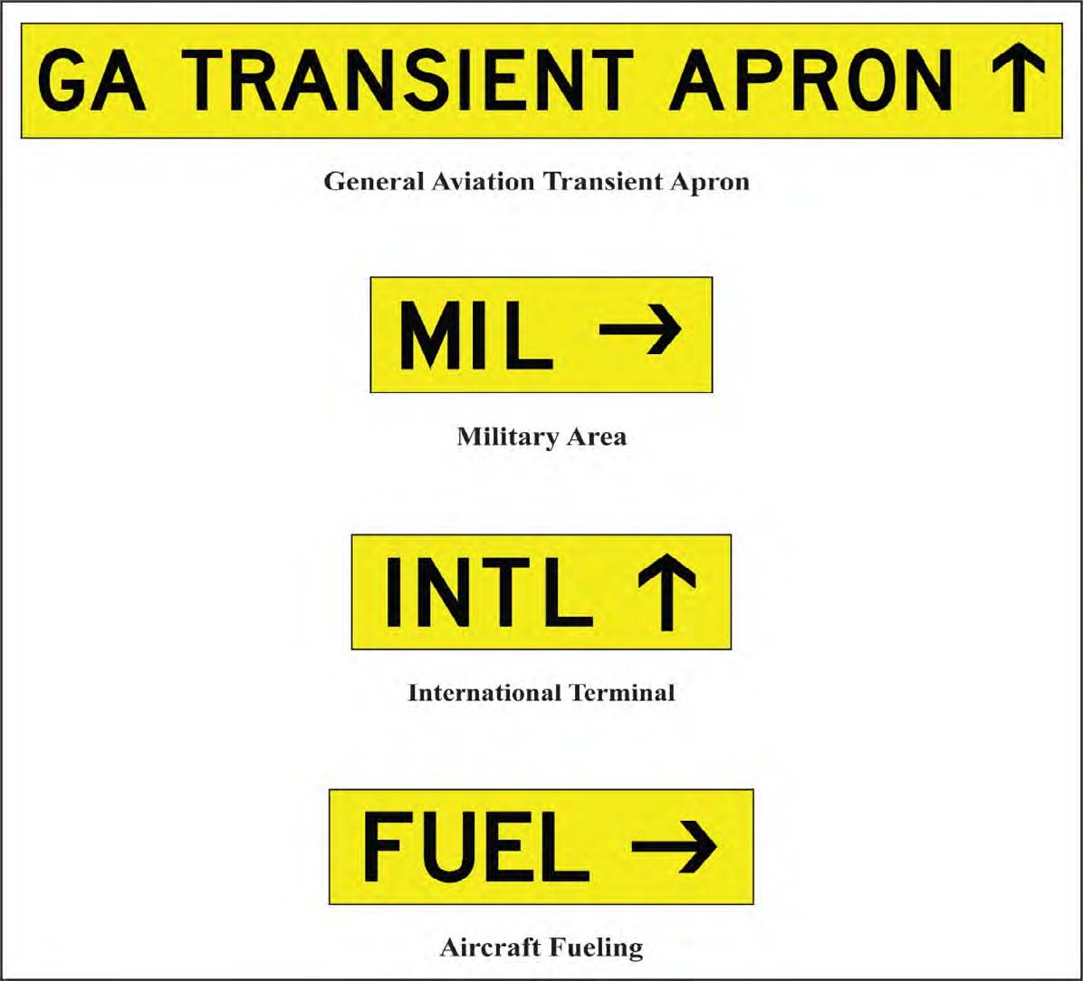
FIG 2-3-39
Outbound Destination Sign for Common Taxi Route to Two Separate Runways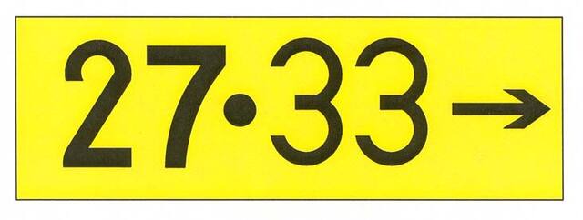
FIG 2-3-40
Destination Sign for Different Taxiing Routes to Two Runways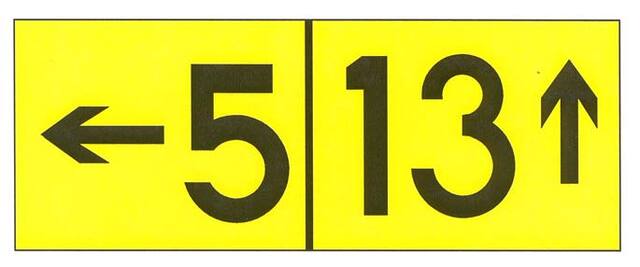
-
Information Signs
Information signs have a yellow background with a black inscription. They are used to provide the pilot with information on such things as areas that cannot be seen from the control tower, applicable radio frequencies, and noise abatement procedures. The airport operator determines the need, size, and location for these signs.
-
Runway Distance Remaining Signs
Runway distance remaining signs have a black background with a white numeral inscription and may be installed along one or both side(s) of the runway. The number on the signs indicates the distance (in thousands of feet) of landing runway remaining. The last sign (i.e., the sign with the numeral “1”) will be located at least 950 feet from the runway end. FIG 2-3-41 shows an example of a runway distance remaining sign.
FIG 2-3-41
Runway Distance Remaining Sign Indicating 3,000 feet of Runway Remaining
-
Aircraft Arresting Systems
- Certain airports are equipped with a means of rapidly stopping military aircraft on a runway. This equipment, normally referred to as EMERGENCY ARRESTING GEAR, generally consists of pendant cables supported over the runway surface by rubber “donuts.” Although most devices are located in the overrun areas, a few of these arresting systems have cables stretched over the operational areas near the ends of a runway.
-
Arresting cables which cross over a runway require special markings on the runway to identify the cable location. These markings consist of 10 feet diameter solid circles painted “identification yellow,” 30 feet on center, perpendicular to the runway centerline across the entire runway width. Additional details are contained in AC 150/5220-9, Aircraft Arresting Systems for Joint Civil/Military Airports.
NOTE-
Aircraft operations on the runway are not restricted by the installation of aircraft arresting devices.
-
Engineered Materials Arresting Systems (EMAS). EMAS, which is constructed of high energy-absorbing materials of selected strength, is located in the safety area beyond the end of the runway. EMAS will be marked with yellow chevrons. EMAS is designed to crush under the weight of commercial aircraft and will exert deceleration forces on the landing gear. These systems do not affect the normal landing and takeoff of airplanes. More information concerning EMAS is in AC 150/5220-22, Engineered Materials Arresting Systems (EMAS) for Aircraft Overruns.
NOTE-
EMAS may be located as close as 35 feet beyond the end of the runway. Aircraft and ground vehicles should never taxi or drive across the EMAS or beyond the end of the runway if EMAS is present.
FIG 2-3-42
Engineered Materials Arresting System (EMAS)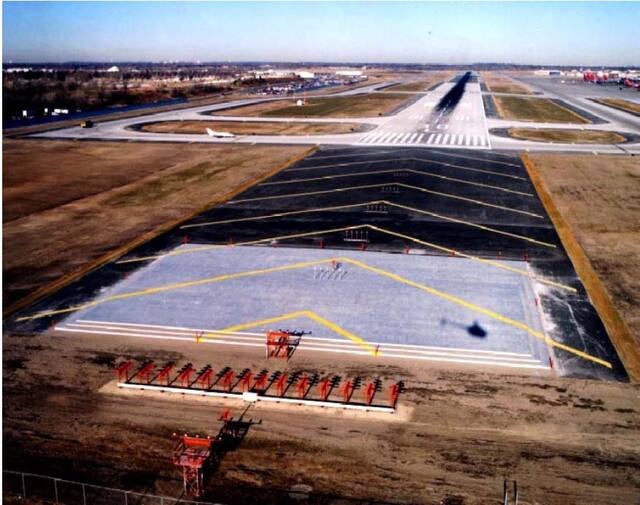
-
Security Identification Display Area (SIDA)
- Security Identification Display Areas (SIDA) are limited access areas that require a badge issued in accordance with procedures in 49 CFR part 1542. A SIDA can include the Air Operations Area (AOA), e.g., aircraft movement area or parking area, or a Secured Area, such as where commercial passengers enplane. The AOA may not be a SIDA, but a Secured Area is always a SIDA. Movement through or into a SIDA is prohibited without authorization and proper identification being displayed. If you are unsure of the location of a SIDA, contact the airport authority for additional information. Airports that have a SIDA will have a description and map detailing boundaries and pertinent features available.
-
Pilots or passengers without proper identification that are observed entering a SIDA may be reported to the Transportation Security Administration (TSA) or airport security and may be subject to civil and criminal fines and prosecution. Pilots are advised to brief passengers accordingly. Report suspicious activity to the TSA by calling AOPA's Airport Watch Program, 866-427-3287. 49 CFR 1540 requires each individual who holds an airman certificate, medical certificate, authorization, or license issued by the FAA to present it for inspection upon a request from TSA.
FIG 2-3-43
Sample SIDA Warning Sign