You have 0 items in your cart

FAR/AIM
>
Aeronautical Information Manual
>
Chapter 2. Aeronautical Lighting and Other Airport Visual Aids
>
Section 3. Airport Marking Aids and Signs
Section 3. Airport Marking Aids and Signs
-
General
- Airport pavement markings and signs provide information that is useful to a pilot during takeoff, landing, and taxiing.
- Uniformity in airport markings and signs from one airport to another enhances safety and improves efficiency. Pilots are encouraged to work with the operators of the airports they use to achieve the marking and sign standards described in this section.
- Pilots who encounter ineffective, incorrect, or confusing markings or signs on an airport should make the operator of the airport aware of the problem. These situations may also be reported under the Aviation Safety Reporting Program as described in paragraph 7-7-1, Aviation Safety Reporting Program. Pilots may also report these situations to the FAA regional airports division.
-
The markings and signs described in this section of the AIM reflect the current FAA recommended standards.
REFERENCE-
AC 150/5340-1, Standards for Airport Markings.
AC 150/5340-18, Standards for Airport Sign Systems.
-
Airport Pavement Markings
-
General. For the purpose of this section, the airport pavement markings have been grouped into four areas:
- Runway Markings.
- Taxiway Markings.
- Holding Position Markings.
- Other Markings.
- Marking Colors. Markings for runways are white. Markings defining the landing area on a heliport are also white except for hospital heliports which use a red “H” on a white cross. Markings for taxiways, areas not intended for use by aircraft (closed and hazardous areas), and holding positions (even if they are on a runway) are yellow.
-
General. For the purpose of this section, the airport pavement markings have been grouped into four areas:
-
Runway Markings
-
General. There are three types of markings for runways: visual, nonprecision instrument, and precision instrument. TBL 2-3-1 identifies the marking elements for each type of runway and TBL 2-3-2 identifies runway threshold markings.
TBL 2-3-1
Runway Marking ElementsMarking Element
Visual Runway
Nonprecision Instrument Runway
Precision Instrument Runway
Designation
X
X
X
Centerline
X
X
X
Threshold
X1
X
X
Aiming Point
X2
X
X
Touchdown Zone
X
Side Stripes
X
1 On runways used, or intended to be used, by international commercial transports.
2 On runways 4,000 feet (1200 m) or longer used by jet aircraft.
FIG 2-3-1
Precision Instrument Runway Markings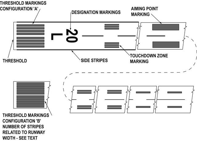
-
Runway Designators. Runway numbers and letters are determined from the approach direction. The runway number is the whole number nearest one‐tenth the magnetic azimuth of the centerline of the runway, measured clockwise from the magnetic north. The letters, differentiate between left (L), right (R), or center (C) parallel runways, as applicable:
- For two parallel runways “L” “R.”
- For three parallel runways “L” “C” “R.”
- Runway Centerline Marking. The runway centerline identifies the center of the runway and provides alignment guidance during takeoff and landings. The centerline consists of a line of uniformly spaced stripes and gaps.
- Runway Aiming Point Marking. The aiming point marking serves as a visual aiming point for a landing aircraft. These two rectangular markings consist of a broad white stripe located on each side of the runway centerline and approximately 1,000 feet from the landing threshold, as shown in FIG 2-3-1, Precision Instrument Runway Markings.
-
Runway Touchdown Zone Markers. The touchdown zone markings identify the touchdown zone for landing operations and are coded to provide distance information in 500 feet (150m) increments. These markings consist of groups of one, two, and three rectangular bars symmetrically arranged in pairs about the runway centerline, as shown in FIG 2-3-1. For runways having touchdown zone markings on both ends, those pairs of markings which extend to within 900 feet (270 m) of the midpoint between the thresholds are eliminated.
FIG 2-3-2
Nonprecision Instrument Runway and Visual Runway Markings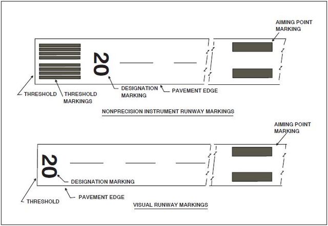
- Runway Side Stripe Marking. Runway side stripes delineate the edges of the runway. They provide a visual contrast between runway and the abutting terrain or shoulders. Side stripes consist of continuous white stripes located on each side of the runway as shown in FIG 2-3-4.
- Runway Shoulder Markings. Runway shoulder stripes may be used to supplement runway side stripes to identify pavement areas contiguous to the runway sides that are not intended for use by aircraft. Runway shoulder stripes are yellow. (See FIG 2-3-5.)
-
Runway Threshold Markings. Runway threshold markings come in two configurations. They either consist of eight longitudinal stripes of uniform dimensions disposed symmetrically about the runway centerline (as shown in FIG 2-3-1) or the number of stripes is related to the runway width as indicated in TBL 2-3-2. A threshold marking helps identify the beginning of the runway that is available for landing. In some instances, the landing threshold may be relocated or displaced.
TBL 2-3-2
Number of Runway Threshold StripesRunway Width
Number of Stripes
60 feet (18 m)
4
75 feet (23 m)
6
100 feet (30 m)
8
150 feet (45 m)
12
200 feet (60 m)
16
- Relocation of a Threshold.Sometimes construction, maintenance, or other activities require the threshold to be relocated towards the rollout end of the runway. (See FIG 2-3-3.) When a threshold is relocated, it closes not only a set portion of the approach end of a runway, but also shortens the length of the opposite direction runway. In these cases, a NOTAM should be issued by the airport operator identifying the portion of the runway that is closed (for example, 10/28 W 900 CLSD). Because the duration of the relocation can vary from a few hours to several months, methods identifying the new threshold may vary. One common practice is to use a ten feet wide white threshold bar across the width of the runway. Although the runway lights in the area between the old threshold and new threshold will not be illuminated, the runway markings in this area may or may not be obliterated, removed, or covered.
-
Displaced Threshold. A displaced threshold is a threshold located at a point on the runway other than the designated beginning of the runway. Displacement of a threshold reduces the length of runway available for landings. The portion of runway behind a displaced threshold is available for takeoffs in either direction and landings from the opposite direction. A ten feet wide white threshold bar is located across the width of the runway at the displaced threshold. White arrows are located along the centerline in the area between the beginning of the runway and displaced threshold. White arrow heads are located across the width of the runway just prior to the threshold bar, as shown in FIG 2-3-4.
NOTE-
Airport operator. When reporting the relocation or displacement of a threshold, the airport operator should avoid language which confuses the two.
-
Demarcation Bar. A demarcation bar delineates a runway with a displaced threshold from a blast pad, stopway, or taxiway that precedes the runway. A demarcation bar is 3 feet (1m) wide and yellow, since it is not located on the runway, as shown in FIG 2-3-6.
- Chevrons. These markings are used to show pavement areas aligned with the runway that are unusable for landing, takeoff, and taxiing. Chevrons are yellow. (See FIG 2-3-7.)
-
Runway Threshold Bar. A threshold bar delineates the beginning of the runway that is available for landing when the threshold has been relocated or displaced. A threshold bar is 10 feet (3m) in width and extends across the width of the runway, as shown in FIG 2-3-4.
FIG 2-3-3
Relocation of a Threshold with Markings for Taxiway Aligned with Runway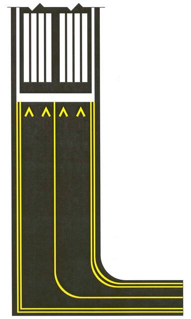
FIG 2-3-4
Displaced Threshold Markings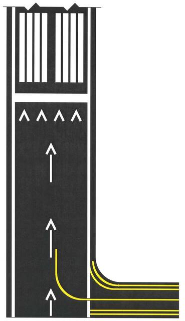
FIG 2-3-5
Runway Shoulder Markings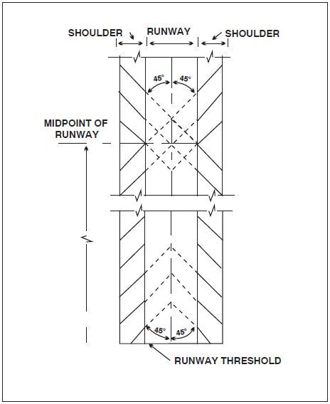
-
General. There are three types of markings for runways: visual, nonprecision instrument, and precision instrument. TBL 2-3-1 identifies the marking elements for each type of runway and TBL 2-3-2 identifies runway threshold markings.
-
Taxiway Markings
-
General. All taxiways should have centerline markings and runway holding position markings whenever they intersect a runway. Taxiway edge markings are present whenever there is a need to separate the taxiway from a pavement that is not intended for aircraft use or to delineate the edge of the taxiway. Taxiways may also have shoulder markings and holding position markings for Instrument Landing System (ILS) critical areas and taxiway/taxiway intersection markings.
REFERENCE-
AIM, Para 2-3-5, Holding Position Markings.
-
Taxiway Centerline.
- Normal Centerline. The taxiway centerline is a single continuous yellow line, 6 inches (15 cm) to 12 inches (30 cm) in width. This provides a visual cue to permit taxiing along a designated path. Ideally, the aircraft should be kept centered over this line during taxi. However, being centered on the taxiway centerline does not guarantee wingtip clearance with other aircraft or other objects.
- Enhanced Centerline. At some airports, mostly the larger commercial service airports, an enhanced taxiway centerline will be used. The enhanced taxiway centerline marking consists of a parallel line of yellow dashes on either side of the normal taxiway centerline. The taxiway centerlines are enhanced for a maximum of 150 feet prior to a runway holding position marking. The purpose of this enhancement is to warn the pilot that he/she is approaching a runway holding position marking and should prepare to stop unless he/she has been cleared onto or across the runway by ATC. (See FIG 2-3-8.)
-
Taxiway Edge Markings. Taxiway edge markings are used to define the edge of the taxiway. They are primarily used when the taxiway edge does not correspond with the edge of the pavement. There are two types of markings depending upon whether the aircraft is supposed to cross the taxiway edge:
- Continuous Markings.These consist of a continuous double yellow line, with each line being at least 6 inches (15 cm) in width spaced 6 inches (15 cm) apart. They are used to define the taxiway edge from the shoulder or some other abutting paved surface not intended for use by aircraft.
- Dashed Markings. These markings are used when there is an operational need to define the edge of a taxiway or taxilane on a paved surface where the adjoining pavement to the taxiway edge is intended for use by aircraft (for example, an apron). Dashed taxiway edge markings consist of a broken double yellow line, with each line being at least 6 inches (15 cm) in width, spaced 6 inches (15 cm) apart (edge to edge). These lines are 15 feet (4.5 m) in length with 25 foot (7.5 m) gaps. (See FIG 2-3-9.)
-
Taxi Shoulder Markings. Taxiways, holding bays, and aprons are sometimes provided with paved shoulders to prevent blast and water erosion. Although shoulders may have the appearance of full strength pavement, they are not intended for use by aircraft and may be unable to support an aircraft. Usually the taxiway edge marking will define this area. Where conditions exist such as islands or taxiway curves that may cause confusion as to which side of the edge stripe is for use by aircraft, taxiway shoulder markings may be used to indicate the pavement is unusable. Taxiway shoulder markings are yellow. (See FIG 2-3-10.)
FIG 2-3-6
Markings for Blast Pad or Stopway or Taxiway Preceding a Displaced Threshold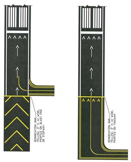
FIG 2-3-7
Markings for Blast Pads and Stopways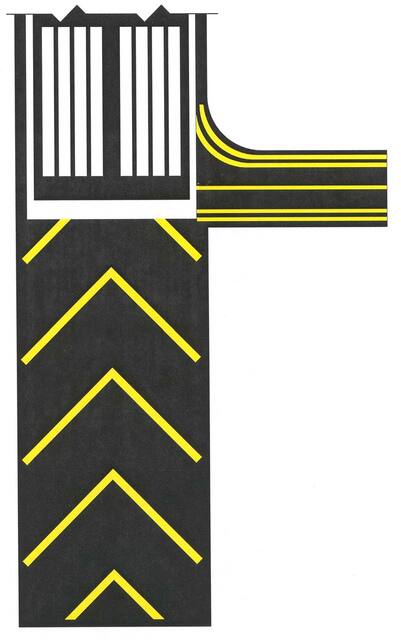
FIG 2-3-8
Enhanced Taxiway Centerline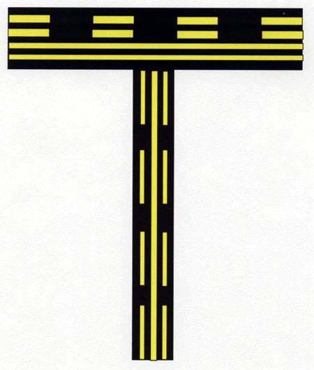
FIG 2-3-9
Dashed Markings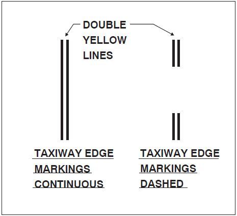
-
Surface Painted Taxiway Direction Signs. Surface painted taxiway direction signs have a yellow background with a black inscription, and are provided when it is not possible to provide taxiway direction signs at intersections, or when necessary to supplement such signs. These markings are located adjacent to the centerline with signs indicating turns to the left being on the left side of the taxiway centerline, and signs indicating turns to the right being on the right side of the centerline. (See FIG 2-3-11.)
FIG 2-3-10
Taxi Shoulder Markings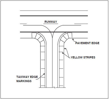
- Surface Painted Location Signs. Surface painted location signs have a black background with a yellow inscription. When necessary, these markings are used to supplement location signs located along side the taxiway and assist the pilot in confirming the designation of the taxiway on which the aircraft is located. These markings are located on the right side of the centerline. (See FIG 2-3-11.)
-
Geographic Position Markings. These markings are located at points along low visibility taxi routes designated in the airport's Surface Movement Guidance Control System (SMGCS) plan. They are used to identify the location of taxiing aircraft during low visibility operations. Low visibility operations are those that occur when the runway visible range (RVR) is below 1200 feet (360m). They are positioned to the left of the taxiway centerline in the direction of taxiing. (See FIG 2-3-12.) The geographic position marking is a circle comprised of an outer black ring contiguous to a white ring with a pink circle in the middle. When installed on asphalt or other dark‐colored pavements, the white ring and the black ring are reversed (i.e., the white ring becomes the outer ring and the black ring becomes the inner ring). It is designated with either a number or a number and letter. The number corresponds to the consecutive position of the marking on the route.
FIG 2-3-11
Surface Painted Signs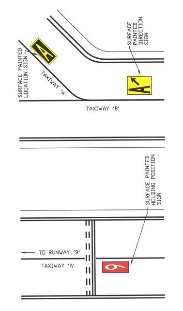
-
General. All taxiways should have centerline markings and runway holding position markings whenever they intersect a runway. Taxiway edge markings are present whenever there is a need to separate the taxiway from a pavement that is not intended for aircraft use or to delineate the edge of the taxiway. Taxiways may also have shoulder markings and holding position markings for Instrument Landing System (ILS) critical areas and taxiway/taxiway intersection markings.
-
Holding Position Markings
-
Runway Holding Position Markings. For runways, these markings indicate where aircraft MUST STOP when approaching a runway. They consist of four yellow lines, two solid and two dashed, spaced six or twelve inches apart, and extending across the width of the taxiway or runway. The solid lines are always on the side where the aircraft must hold. There are three locations where runway holding position markings are encountered.
-
Runway Holding Position Markings on Taxiways. These markings identify the locations on a taxiway where aircraft MUST STOP when a clearance has not been issued to proceed onto the runway. Generally, runway holding position markings also identify the boundary of the runway safety area (RSA) for aircraft exiting the runway. Runway holding position markings are shown in FIG 2-3-13 and FIG 2-3-16. When instructed by ATC, “Hold short of Runway XX,” the pilot MUST STOP so that no part of the aircraft extends beyond the runway holding position marking. When approaching runways at airports with an operating control tower, pilots must not cross the runway holding position marking without ATC clearance. Pilots approaching runways at airports without an operating control tower must ensure adequate separation from other aircraft, vehicles, and pedestrians prior to crossing the holding position markings. An aircraft exiting a runway is not clear of the runway until all parts of the aircraft have crossed the applicable holding position marking.
NOTE-
Runway holding position markings identify the beginning of an RSA, and a pilot MUST STOP to get clearance before crossing (at airports with operating control towers).
REFERENCE-
AIM, Para 4-3-21, Exiting the Runway After Landing.
- Runway Holding Position Markings on Runways.These markings identify the locations on runways where aircraft MUST STOP. These markings are located on runways used by ATC for Land And Hold Short Operations (for example, see FIG 4-3-8) and Taxiing operations. For taxiing operations, the pilot MUST STOP prior to the holding position markings unless explicitly authorized to cross by ATC. A sign with a white inscription on a red background is located adjacent to these holding position markings. (See FIG 2-3-14.) The holding position markings are placed on runways prior to the intersection with another runway, or some designated point. Pilots receiving and accepting instructions “Cleared to land Runway XX, hold short of Runway YY” from ATC must either exit Runway XX prior to the holding position markings, or stop at the holding position markings prior to Runway YY. Otherwise, pilots are authorized to use the entire landing length of the runway and disregard the holding position markings.
- Holding Position Markings on Taxiways Located in Runway Approach Areas.These markings are used at some airports where it is necessary to hold an aircraft on a taxiway located in the approach or departure area of a runway so that the aircraft does not interfere with the operations on that runway. This marking is collocated with the runway approach/departure area holding position sign. When specifically instructed by ATC, “Hold short of Runway XX approach or Runway XX departure area,” the pilot MUST STOP so that no part of the aircraft extends beyond the holding position marking. (See Subparagraph 2-3-8b2, Runway Approach Area Holding Position Sign, and FIG 2-3-15.)
-
Runway Holding Position Markings on Taxiways. These markings identify the locations on a taxiway where aircraft MUST STOP when a clearance has not been issued to proceed onto the runway. Generally, runway holding position markings also identify the boundary of the runway safety area (RSA) for aircraft exiting the runway. Runway holding position markings are shown in FIG 2-3-13 and FIG 2-3-16. When instructed by ATC, “Hold short of Runway XX,” the pilot MUST STOP so that no part of the aircraft extends beyond the runway holding position marking. When approaching runways at airports with an operating control tower, pilots must not cross the runway holding position marking without ATC clearance. Pilots approaching runways at airports without an operating control tower must ensure adequate separation from other aircraft, vehicles, and pedestrians prior to crossing the holding position markings. An aircraft exiting a runway is not clear of the runway until all parts of the aircraft have crossed the applicable holding position marking.
-
Holding Position Markings for Instrument Landing System (ILS). Holding position markings for ILS critical areas consist of two yellow solid lines spaced two feet apart connected by pairs of solid lines spaced ten feet apart extending across the width of the taxiway as shown. (See FIG 2-3-16.) A sign with an inscription in white on a red background is located adjacent to these hold position markings. When instructed by ATC to hold short of the ILS critical area, pilots MUST STOP so that no part of the aircraft extends beyond the holding position marking. When approaching the holding position marking, pilots must not cross the marking without ATC clearance. The ILS critical area is not clear until all parts of the aircraft have crossed the applicable holding position marking.
REFERENCE-
AIM, Para 1-1-9, Instrument Landing System (ILS).
- Holding Position Markings for Intersecting Taxiways Holding position markings for intersecting taxiways consist of a single dashed line extending across the width of the taxiway as shown. (See FIG 2-3-17.) They are located on taxiways where ATC holds aircraft short of a taxiway intersection. When instructed by ATC, “Hold short of Taxiway XX,” the pilot MUST STOP so that no part of the aircraft extends beyond the holding position marking. When the marking is not present, the pilot MUST STOP the aircraft at a point which provides adequate clearance from an aircraft on the intersecting taxiway.
-
Surface Painted Holding Position Signs. Surface painted holding position signs have a red background with a white inscription and supplement the signs located at the holding position. This type of marking is normally used where the width of the holding position on the taxiway is greater than 200 feet (60 m). It is located to the left side of the taxiway centerline on the holding side and prior to the holding position marking. (See FIG 2-3-11.)
FIG 2-3-12
Geographic Position Markings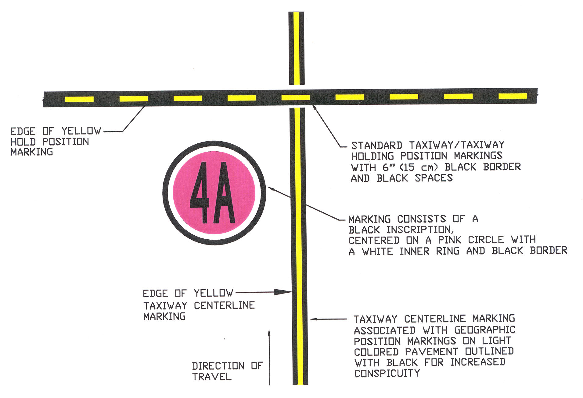
FIG 2-3-13
Runway Holding Position Markings on Taxiway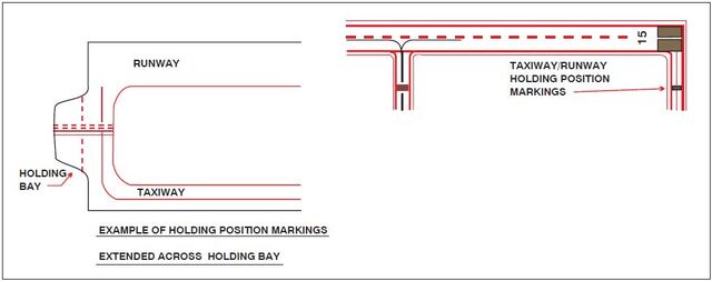
FIG 2-3-14
Runway Holding Position Markings on Runways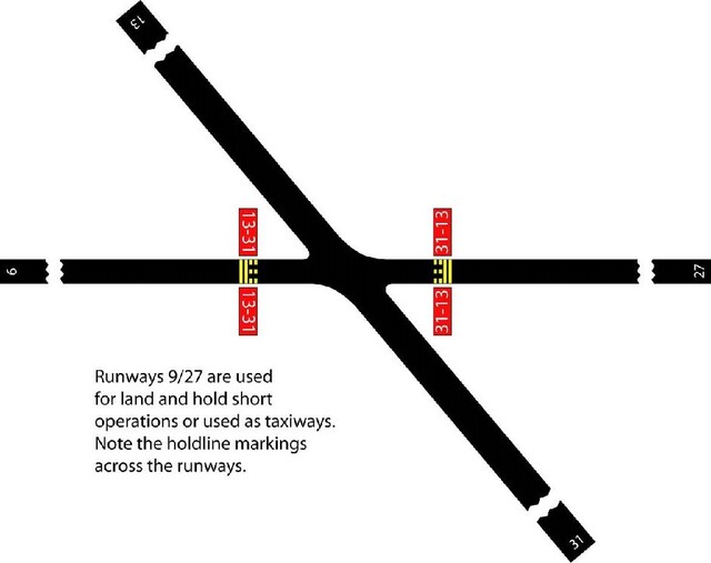
FIG 2-3-15
Taxiways Located in Runway Approach and Departure Areas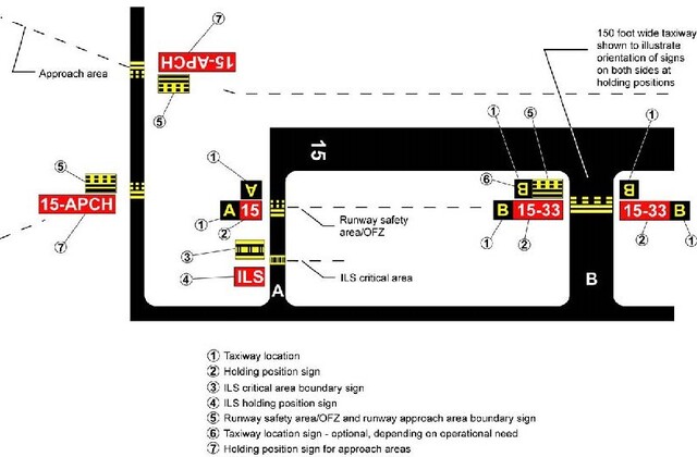
NOTE-
- Refer to Advisory Circular 150/5300-13 for additional information on obstruction surfaces.
- Because Taxiway C does not enter the departure area of Runway 33, the sign on Taxiway C does not include the “33 DEP” legend.
- The location of a holding position is relative to the point on the aircraft that infringes the surface; for inclining surfaces such as an approach surface, the location of the holdline position may differ from the location of the infringement point.
FIG 2-3-16
Holding Position Markings: ILS Critical Area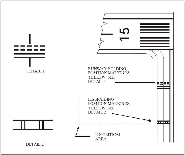
-
Runway Holding Position Markings. For runways, these markings indicate where aircraft MUST STOP when approaching a runway. They consist of four yellow lines, two solid and two dashed, spaced six or twelve inches apart, and extending across the width of the taxiway or runway. The solid lines are always on the side where the aircraft must hold. There are three locations where runway holding position markings are encountered.
-
Other Markings
- Vehicle Roadway Markings. The vehicle roadway markings are used when necessary to define a pathway for vehicle operations on or crossing areas that are also intended for aircraft. These markings consist of a white solid line to delineate each edge of the roadway and a dashed line to separate lanes within the edges of the roadway. In lieu of the solid lines, zipper markings may be used to delineate the edges of the vehicle roadway. (See FIG 2-3-18.) Details of the zipper markings are shown in FIG 2-3-19.
-
VOR Receiver Checkpoint Markings. The VOR receiver checkpoint marking allows the pilot to check aircraft instruments with navigational aid signals. It consists of a painted circle with an arrow in the middle; the arrow is aligned in the direction of the checkpoint azimuth. This marking, and an associated sign, is located on the airport apron or taxiway at a point selected for easy access by aircraft but where other airport traffic is not to be unduly obstructed. (See FIG 2-3-20.)
NOTE-
The associated sign contains the VOR station identification letter and course selected (published) for the check, the words “VOR check course,” and DME data (when applicable). The color of the letters and numerals are black on a yellow background.
EXAMPLE-
DCA 176-356
VOR check course
DME XXXFIG 2-3-17
Holding Position Markings: Taxiway/Taxiway Intersections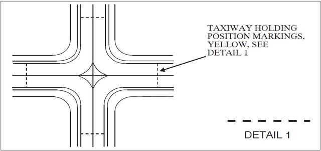
FIG 2-3-18
Vehicle Roadway Markings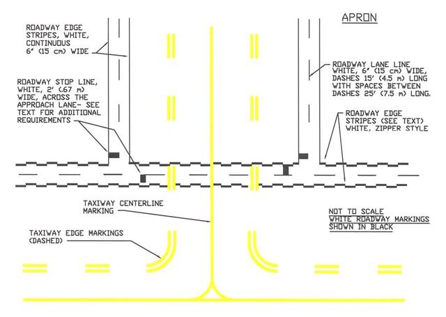
FIG 2-3-19
Roadway Edge Stripes, White, Zipper Style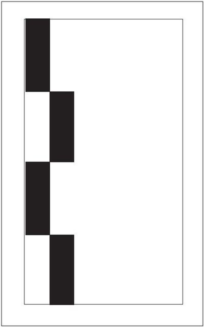
-
Nonmovement Area Boundary Markings. These markings delineate the movement area (i.e., area under ATC). These markings are yellow and located on the boundary between the movement and nonmovement area. The nonmovement area boundary markings consist of two yellow lines (one solid and one dashed) 6 inches (15cm) in width. The solid line is located on the nonmovement area side, while the dashed yellow line is located on the movement area side. The nonmovement boundary marking area is shown in FIG 2-3-21.
FIG 2-3-20
Ground Receiver Checkpoint Markings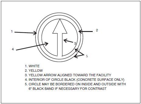
FIG 2-3-21
Nonmovement Area Boundary Markings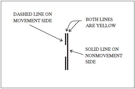
FIG 2-3-22
Closed or Temporarily Closed Runway and Taxiway Markings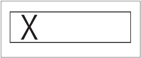
-
Marking and Lighting of Permanently Closed Runways and Taxiways. For runways and taxiways which are permanently closed, the lighting circuits will be disconnected. The runway threshold, runway designation, and touchdown markings are obliterated and yellow crosses are placed at each end of the runway and at 1,000 foot intervals. (See FIG 2-3-22.)
FIG 2-3-23
Helicopter Landing Areas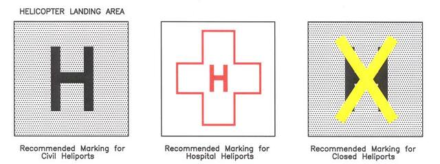
-
Temporarily Closed Runways and Taxiways.To provide a visual indication to pilots that a runway is temporarily closed, crosses are placed on the runway only at each end of the runway. The crosses are yellow in color. (See FIG 2-3-22.)
- A raised lighted yellow cross may be placed on each runway end in lieu of the markings described in Subparagraph e, Temporarily Closed Runways and Taxiways, to indicate the runway is closed.
- A visual indication may not be present depending on the reason for the closure, duration of the closure, airfield configuration, and the existence and the hours of operation of an airport traffic control tower. Pilots should check NOTAMs and the Automated Terminal Information System (ATIS) for local runway and taxiway closure information.
- Temporarily closed taxiways are usually treated as hazardous areas, in which no part of an aircraft may enter, and are blocked with barricades. However, as an alternative, a yellow cross may be installed at each entrance to the taxiway.
- Helicopter Landing Areas.The markings illustrated in FIG 2-3-23 are used to identify the landing and takeoff area at a public use heliport and hospital heliport. The letter “H” in the markings is oriented to align with the intended direction of approach. FIG 2-3-23 also depicts the markings for a closed airport.
-
Airport Signs
There are six types of signs installed on airfields: mandatory instruction signs, location signs, direction signs, destination signs, information signs, and runway distance remaining signs. The characteristics and use of these signs are discussed in paragraph 2-3-8, Mandatory Instruction Signs, through paragraph 2-3-13, Runway Distance Remaining Signs.
REFERENCE-
AC150/5340-18, Standards for Airport Sign Systems for Detailed Information on Airport Signs.
FIG 2-3-24
Runway Holding Position Sign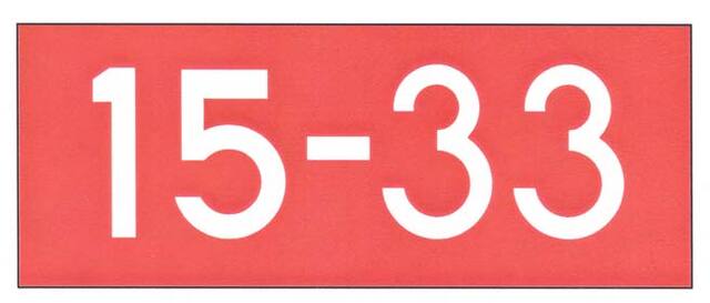
FIG 2-3-25
Holding Position Sign at Beginning of Takeoff Runway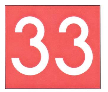
-
Mandatory Instruction Signs
-
These signs have a red background with a white inscription and are used to denote:
- An entrance to a runway or critical area; and
- Areas where an aircraft is prohibited from entering.
-
Typical mandatory signs and applications are:
-
Runway Holding Position Sign. This sign is located at the holding position on taxiways that intersect a runway or on runways that intersect other runways. The inscription on the sign contains the designation of the intersecting runway, as shown in FIG 2-3-24. The runway numbers on the sign are arranged to correspond to the respective runway threshold. For example, “15-33” indicates that the threshold for Runway 15 is to the left and the threshold for Runway 33 is to the right.
-
On taxiways that intersect the beginning of the takeoff runway, only the designation of the takeoff runway may appear on the sign (as shown in FIG 2-3-25), while all other signs will have the designation of both runway directions.
FIG 2-3-26
Holding Position Sign for a Taxiway that Intersects the Intersection of Two Runways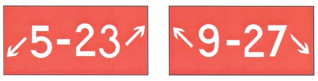
FIG 2-3-27
Holding Position Sign for Runway Approach and Departure Areas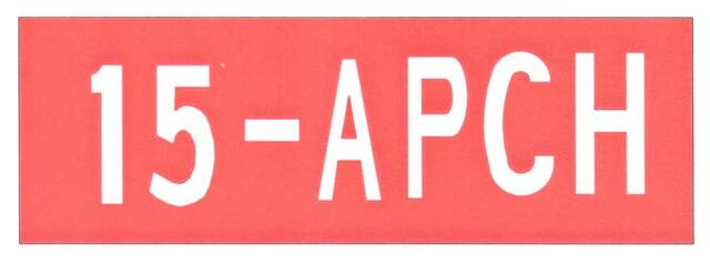
- If the sign is located on a taxiway that intersects the intersection of two runways, the designations for both runways will be shown on the sign along with arrows showing the approximate alignment of each runway, as shown in FIG 2-3-26. In addition to showing the approximate runway alignment, the arrow indicates the direction to the threshold of the runway whose designation is immediately next to the arrow.
- A runway holding position sign on a taxiway will be installed adjacent to holding position markings on the taxiway pavement. On runways, holding position markings will be located only on the runway pavement adjacent to the sign, if the runway is normally used by ATC for “Land, Hold Short” operations or as a taxiway. The holding position markings are described in paragraph 2-3-5, Holding Position Markings.
-
On taxiways that intersect the beginning of the takeoff runway, only the designation of the takeoff runway may appear on the sign (as shown in FIG 2-3-25), while all other signs will have the designation of both runway directions.
-
Runway Approach Area Holding Position Sign. At some airports, it is necessary to hold an aircraft on a taxiway located in the approach or departure area for a runway so that the aircraft does not interfere with operations on that runway. FIG 2-3-15 depicts common situations. A sign with the runway designation(s) and the protected area(s) will be located at applicable holding positions on the taxiway. For locations protecting only the approach area, the holding position on the taxiway includes a sign identifying the approach end runway designation (e.g., 15) followed by a dash (-) and the letters “APCH”. For locations protecting both the approach and departure areas, the holding position on the taxiway includes a sign with the approach end runway designation and letters “APCH” followed by a dash (-), the departure end runway designation and the letters “DEP”. The arrangement of the runway designations and protected areas legend on the sign reflects the orientation of the runway as viewed from the holding position. Holding position markings in accordance with paragraph 2-3-5, Holding Position Markings, are co-located on the taxiway pavement in line with the sign. Examples of these signs are shown in FIG 2-3-27.
FIG 2-3-28
Holding Position Sign for ILS Critical Area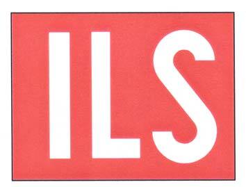
FIG 2-3-29
Sign Prohibiting Aircraft Entry into an Area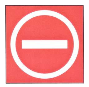
- ILS Critical Area Holding Position Sign.At some airports, when the instrument landing system is being used, it is necessary to hold an aircraft on a taxiway at a location other than the holding position described in Paragraph 2-3-5, Holding Position Markings. In these situations, the holding position sign for these operations will have the inscription “ILS” and be located adjacent to the holding position marking on the taxiway described in paragraph 2-3-5. An example of this sign is shown in FIG 2-3-28.
-
No Entry Sign.This sign, shown in FIG 2-3-29, prohibits an aircraft from entering an area. Typically, this sign would be located on a taxiway intended to be used in only one direction or at the intersection of vehicle roadways with runways, taxiways, or aprons where the roadway may be mistaken as a taxiway or other aircraft movement surface.
NOTE-
Holding position signs provide the pilot with a visual cue as to the location of the holding position marking.
REFERENCE-
AIM, Para 2-3-5, Holding Position Markings.
FIG 2-3-30
Taxiway Location Sign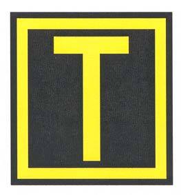
FIG 2-3-31
Taxiway Location Sign Collocated with Runway Holding Position Sign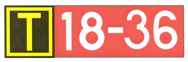
-
Runway Holding Position Sign. This sign is located at the holding position on taxiways that intersect a runway or on runways that intersect other runways. The inscription on the sign contains the designation of the intersecting runway, as shown in FIG 2-3-24. The runway numbers on the sign are arranged to correspond to the respective runway threshold. For example, “15-33” indicates that the threshold for Runway 15 is to the left and the threshold for Runway 33 is to the right.
-
These signs have a red background with a white inscription and are used to denote:
-
Location Signs
-
Location signs are used to identify either a taxiway or runway on which the aircraft is located. Other location signs provide a visual cue to pilots to assist them in determining when they have exited an area. The various location signs are described below.
-
Taxiway Location Sign.This sign has a black background with a yellow inscription and yellow border, as shown in FIG 2-3-30. The inscription is the designation of the taxiway on which the aircraft is located. These signs are installed along taxiways either by themselves or in conjunction with direction signs or runway holding position signs. (See FIG 2-3-35 and FIG 2-3-31.)
FIG 2-3-32
Runway Location Sign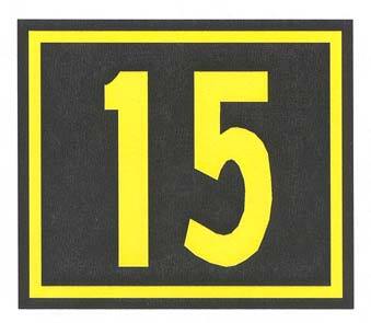
FIG 2-3-33
Runway Boundary Sign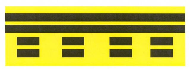
- Runway Location Sign.This sign has a black background with a yellow inscription and yellow border, as shown in FIG 2-3-32. The inscription is the designation of the runway on which the aircraft is located. These signs are intended to complement the information available to pilots through their magnetic compass and typically are installed where the proximity of two or more runways to one another could cause pilots to be confused as to which runway they are on.
-
Runway Boundary Sign.This sign has a yellow background with a black inscription with a graphic depicting the pavement holding position marking, as shown in FIG 2-3-33. This sign, which faces the runway and is visible to the pilot exiting the runway, is located adjacent to the holding position marking on the pavement. The sign is intended to provide pilots with another visual cue which they can use as a guide in deciding when they are “clear of the runway.”
FIG 2-3-34
ILS Critical Area Boundary Sign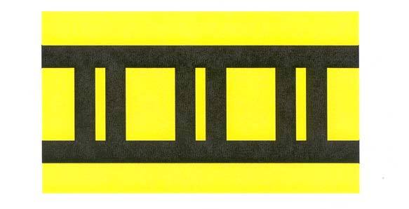
- ILS Critical Area Boundary Sign. This sign has a yellow background with a black inscription with a graphic depicting the ILS pavement holding position marking as shown in FIG 2-3-34. This sign is located adjacent to the ILS holding position marking on the pavement and can be seen by pilots leaving the critical area. The sign is intended to provide pilots with another visual cue which they can use as a guide in deciding when they are “clear of the ILS critical area.”
-
Taxiway Location Sign.This sign has a black background with a yellow inscription and yellow border, as shown in FIG 2-3-30. The inscription is the designation of the taxiway on which the aircraft is located. These signs are installed along taxiways either by themselves or in conjunction with direction signs or runway holding position signs. (See FIG 2-3-35 and FIG 2-3-31.)
-
Location signs are used to identify either a taxiway or runway on which the aircraft is located. Other location signs provide a visual cue to pilots to assist them in determining when they have exited an area. The various location signs are described below.
-
Direction Signs
- Direction signs have a yellow background with a black inscription. The inscription identifies the designation(s) of the intersecting taxiway(s) leading out of the intersection that a pilot would normally be expected to turn onto or hold short of. Each designation is accompanied by an arrow indicating the direction of the turn.
- Except as noted in subparagraph e, each taxiway designation shown on the sign is accompanied by only one arrow. When more than one taxiway designation is shown on the sign, each designation and its associated arrow is separated from the other taxiway designations by either a vertical message divider or a taxiway location sign as shown in FIG 2-3-35.
- Direction signs are normally located on the left prior to the intersection. When used on a runway to indicate an exit, the sign is located on the same side of the runway as the exit. FIG 2-3-36 shows a direction sign used to indicate a runway exit.
- The taxiway designations and their associated arrows on the sign are arranged clockwise starting from the first taxiway on the pilot's left. (See FIG 2-3-35.)
- If a location sign is located with the direction signs, it is placed so that the designations for all turns to the left will be to the left of the location sign; the designations for continuing straight ahead or for all turns to the right would be located to the right of the location sign. (See FIG 2-3-35.)
-
When the intersection is comprised of only one crossing taxiway, it is permissible to have two arrows associated with the crossing taxiway, as shown in FIG 2-3-37. In this case, the location sign is located to the left of the direction sign.
FIG 2-3-35
Direction Sign Array with Location Sign on Far Side of Intersection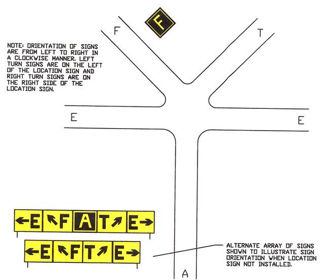
FIG 2-3-36
Direction Sign for Runway Exit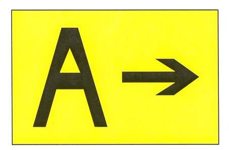
FIG 2-3-37
Direction Sign Array for Simple Intersection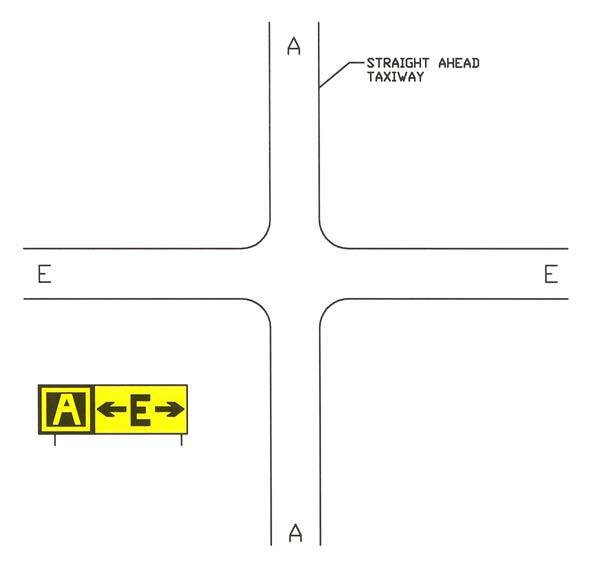
-
Destination Signs
- Destination signs have a yellow background with a black inscription indicating a taxi route to a destination on the airport. These signs supplement standard taxiway direction signs to optimize taxi paths to specific areas of the airport.
- Destination signs always have an arrow showing the direction of the taxi route to the destination indicated on the sign. Where the destination sign arrow indicates a turn, the sign location is prior to the intersection. The sign may reside on the opposite side of an intersection for straight ahead paths and for ending taxiway intersections.
-
Inbound destination signs identify a taxi path to specific areas of the airport. Sign legends are typically short descriptions or abbreviations of the destination. FIG 2-3-38 shows examples of typical inbound destination signs. Common sign legends include:
-
APRON. General parking, servicing, and loading areas
- FBO Apron. An apron where itinerant general aviation operators can park their aircraft and expect to have access to traditional Fixed Base Operator services subject to terms and conditions.
- GA Transient Apron. An apron where itinerant general aviation operators can park their aircraft without FBO services and subject to terms and conditions.
- GA Tenant Apron. An area designated for parking of based general aviation aircraft, e.g., tie down area.
- North/South/East/West Apron. An apron designation describing relative location on the airport.
- CARGO. Areas set aside for cargo handling.
- CIVIL. Areas set aside for civil aircraft.
- FUEL. Areas where aircraft receive fuel or related services.
- INTL. Areas set aside for handling international flights.
-
MIL. Areas set aside for military aircraft.
- ANG. Area reserved for Air National Guard
- USN. Area reserved for U.S. Navy
- PARKING. Alternative name for apron area.
- PAX. Areas set aside for passenger handling.
- RAMP. Name synonymous with APRON.
- TERM. Gate positions at which aircraft load or unload passengers and cargo.
-
APRON. General parking, servicing, and loading areas
- Outbound destination signs identify the general direction to departure runways. The sign legend consists of direction arrow(s) and the applicable runway designations. FIG 2-3-39 is an example of a typical outbound destination sign.
- When a sign indicates the inscription for two or more destinations having a common taxi route, a “dot” (•) separates the destinations and one arrow indicates the direction of the taxi path, as shown in FIG 2-3-39.
-
When a sign shows the inscription for two or more destinations having different taxiing routes, each destination will have its own arrow to indicate the taxi direction. A vertical black message divider separates each destination, as shown in FIG 2-3-40.
FIG 2-3-38
Inbound Destination Sign Example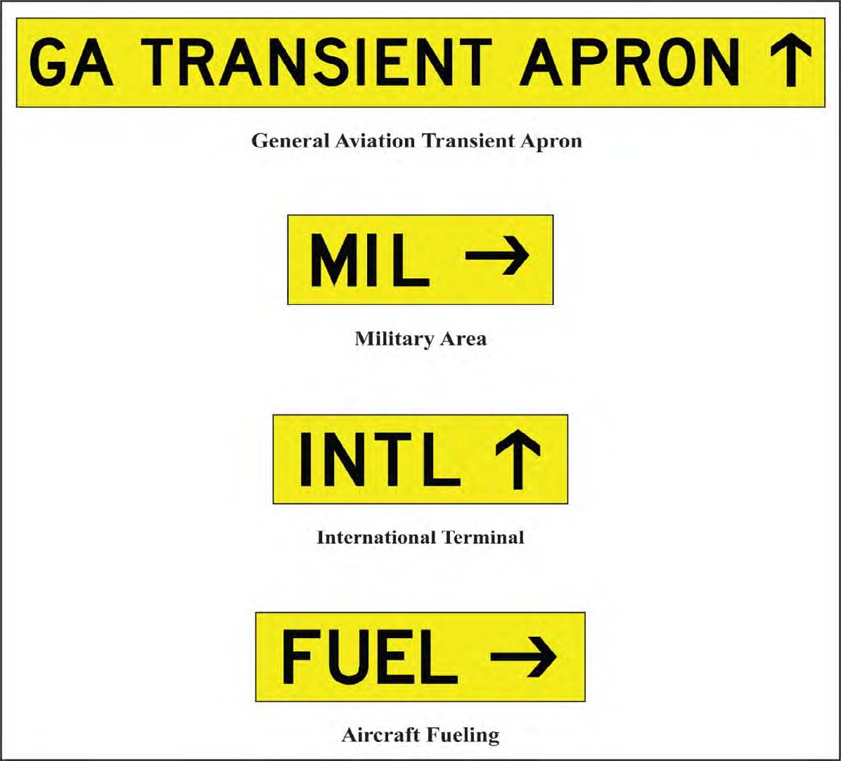
FIG 2-3-39
Outbound Destination Sign for Common Taxi Route to Two Separate Runways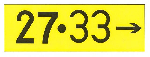
FIG 2-3-40
Destination Sign for Different Taxiing Routes to Two Runways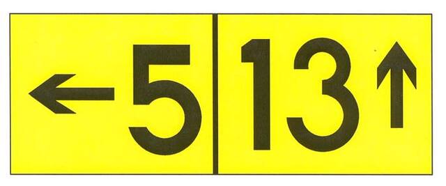
-
Information Signs
Information signs have a yellow background with a black inscription. They are used to provide the pilot with information on such things as areas that cannot be seen from the control tower, applicable radio frequencies, and noise abatement procedures. The airport operator determines the need, size, and location for these signs.
-
Runway Distance Remaining Signs
Runway distance remaining signs have a black background with a white numeral inscription and may be installed along one or both side(s) of the runway. The number on the signs indicates the distance (in thousands of feet) of landing runway remaining. The last sign (i.e., the sign with the numeral “1”) will be located at least 950 feet from the runway end. FIG 2-3-41 shows an example of a runway distance remaining sign.
FIG 2-3-41
Runway Distance Remaining Sign Indicating 3,000 feet of Runway Remaining
-
Aircraft Arresting Systems
- Certain airports are equipped with a means of rapidly stopping military aircraft on a runway. This equipment, normally referred to as EMERGENCY ARRESTING GEAR, generally consists of pendant cables supported over the runway surface by rubber “donuts.” Although most devices are located in the overrun areas, a few of these arresting systems have cables stretched over the operational areas near the ends of a runway.
-
Arresting cables which cross over a runway require special markings on the runway to identify the cable location. These markings consist of 10 feet diameter solid circles painted “identification yellow,” 30 feet on center, perpendicular to the runway centerline across the entire runway width. Additional details are contained in AC 150/5220-9, Aircraft Arresting Systems for Joint Civil/Military Airports.
NOTE-
Aircraft operations on the runway are not restricted by the installation of aircraft arresting devices.
-
Engineered Materials Arresting Systems (EMAS). EMAS, which is constructed of high energy-absorbing materials of selected strength, is located in the safety area beyond the end of the runway. EMAS will be marked with yellow chevrons. EMAS is designed to crush under the weight of commercial aircraft and will exert deceleration forces on the landing gear. These systems do not affect the normal landing and takeoff of airplanes. More information concerning EMAS is in AC 150/5220-22, Engineered Materials Arresting Systems (EMAS) for Aircraft Overruns.
NOTE-
EMAS may be located as close as 35 feet beyond the end of the runway. Aircraft and ground vehicles should never taxi or drive across the EMAS or beyond the end of the runway if EMAS is present.
FIG 2-3-42
Engineered Materials Arresting System (EMAS)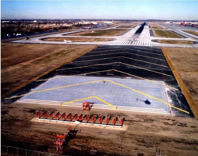
-
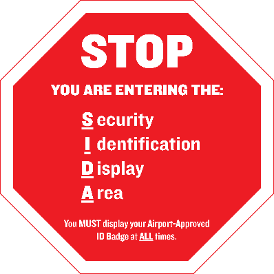
Security Identification Display Area (SIDA)
- Security Identification Display Areas (SIDA) are limited access areas that require a badge issued in accordance with procedures in 49 CFR part 1542. A SIDA can include the Air Operations Area (AOA), e.g., aircraft movement area or parking area, or a Secured Area, such as where commercial passengers enplane. The AOA may not be a SIDA, but a Secured Area is always a SIDA. Movement through or into a SIDA is prohibited without authorization and proper identification being displayed. If you are unsure of the location of a SIDA, contact the airport authority for additional information. Airports that have a SIDA will have a description and map detailing boundaries and pertinent features available.
-
Pilots or passengers without proper identification that are observed entering a SIDA may be reported to the Transportation Security Administration (TSA) or airport security and may be subject to civil and criminal fines and prosecution. Pilots are advised to brief passengers accordingly. Report suspicious activity to the TSA by calling AOPA's Airport Watch Program, 866-427-3287. 49 CFR 1540 requires each individual who holds an airman certificate, medical certificate, authorization, or license issued by the FAA to present it for inspection upon a request from TSA.
FIG 2-3-43
Sample SIDA Warning Sign