You have 0 items in your cart

FAR/AIM
>
Aeronautical Information Manual
>
Chapter 10. Helicopter Operations
>
Section 1. Helicopter IFR Operations
Section 1. Helicopter IFR Operations
-
Helicopter Flight Control Systems
- The certification requirements for helicopters to operate under Instrument Flight Rules (IFR) are contained in 14 CFR part 27, Airworthiness Standards: Normal Category Rotorcraft, and 14 CFR part 29, Airworthiness Standards: Transport Category Rotorcraft. To meet these requirements, helicopter manufacturers usually utilize a set of stabilization and/or Automatic Flight Control Systems (AFCSs).
-
Typically, these systems fall into the following categories:
- Aerodynamic surfaces, which impart some stability or control capability not found in the basic VFR configuration.
- Trim systems, which provide a cyclic centering effect. These systems typically involve a magnetic brake/spring device, and may also be controlled by a four-way switch on the cyclic. This is a system that supports “hands on” flying of the helicopter by the pilot.
- Stability Augmentation Systems (SASs), which provide short-term rate damping control inputs to increase helicopter stability. Like trim systems, SAS supports “hands on” flying.
- Attitude Retention Systems (ATTs), which return the helicopter to a selected attitude after a disturbance. Changes in desired attitude can be accomplished usually through a four-way “beep” switch, or by actuating a “force trim” switch on the cyclic, setting the attitude manually, and releasing. Attitude retention may be a SAS function, or may be the basic “hands off” autopilot function.
- Autopilot Systems (APs), which provide for “hands off” flight along specified lateral and vertical paths, including heading, altitude, vertical speed, navigation tracking, and approach. These systems typically have a control panel for mode selection, and system for indication of mode status. Autopilots may or may not be installed with an associated Flight Director System (FD). Autopilots typically control the helicopter about the roll and pitch axes (cyclic control) but may also include yaw axis (pedal control) and collective control servos.
- FDs, which provide visual guidance to the pilot to fly specific selected lateral and vertical modes of operation. The visual guidance is typically provided as either a “dual cue” (commonly known as a “cross-pointer”) or “single cue” (commonly known as a “vee-bar”) presentation superimposed over the attitude indicator. Some FDs also include a collective cue. The pilot manipulates the helicopter's controls to satisfy these commands, yielding the desired flight path, or may couple the flight director to the autopilot to perform automatic flight along the desired flight path. Typically, flight director mode control and indication is shared with the autopilot.
- In order to be certificated for IFR operation, a specific helicopter may require the use of one or more of these systems, in any combination.
- In many cases, helicopters are certificated for IFR operations with either one or two pilots. Certain equipment is required to be installed and functional for two pilot operations, and typically, additional equipment is required for single pilot operation. These requirements are usually described in the limitations section of the Rotorcraft Flight Manual (RFM).
- In addition, the RFM also typically defines systems and functions that are required to be in operation or engaged for IFR flight in either the single or two pilot configuration. Often, particularly in two pilot operation, this level of augmentation is less than the full capability of the installed systems. Likewise, single pilot operation may require a higher level of augmentation.
-
The RFM also identifies other specific limitations associated with IFR flight. Typically, these limitations include, but are not limited to:
- Minimum equipment required for IFR flight (in some cases, for both single pilot and two pilot operations).
-
Vmini (minimum speed - IFR).
NOTE-
The manufacturer may also recommend a minimum IFR airspeed during instrument approach.
- Vnei (never exceed speed - IFR).
- Maximum approach angle.
- Weight and center of gravity limits.
- Aircraft configuration limitations (such as aircraft door positions and external loads).
- Aircraft system limitations (generators, inverters, etc.).
- System testing requirements (many avionics and AFCS/AP/FD systems incorporate a self-test feature).
- Pilot action requirements (such as the pilot must have his/her hands and feet on the controls during certain operations, such as during instrument approach below certain altitudes).
- It is very important that pilots be familiar with the IFR requirements for their particular helicopter. Within the same make, model and series of helicopter, variations in the installed avionics may change the required equipment or the level of augmentation for a particular operation.
- During flight operations, pilots must be aware of the mode of operation of the augmentation systems, and the control logic and functions employed. For example, during an ILS approach using a particular system in the three-cue mode (lateral, vertical and collective cues), the flight director collective cue responds to glideslope deviation, while the horizontal bar of the “cross-pointer” responds to airspeed deviations. The same system, while flying an ILS in the two-cue mode, provides for the horizontal bar to respond to glideslope deviations. This concern is particularly significant when operating using two pilots. Pilots should have an established set of procedures and responsibilities for the control of flight director/autopilot modes for the various phases of flight. Not only does a full understanding of the system modes provide for a higher degree of accuracy in control of the helicopter, it is the basis for crew identification of a faulty system.
- Relief from the prohibition to takeoff with any inoperative instruments or equipment may be provided through a Minimum Equipment List (see 14 CFR section 91.213 and 14 CFR section 135.179, Inoperative Instruments and Equipment). In many cases, a helicopter configured for single pilot IFR may depart IFR with certain equipment inoperative, provided a crew of two pilots is used. Pilots are cautioned to ensure the pilot-in-command and second-in-command meet the requirements of 14 CFR section 61.58, Pilot-in-Command Proficiency Check: Operation of Aircraft Requiring More Than One Pilot Flight Crewmember, and 14 CFR section 61.55, Second-in-Command Qualifications, or 14 CFR part 135, Operating Requirements: Commuter and On-Demand Operations, Subpart E, Flight Crewmember Requirements, and Subpart G, Crewmember Testing Requirements, as appropriate.
- Experience has shown that modern AFCS/AP/FD equipment installed in IFR helicopters can, in some cases, be very complex. This complexity requires the pilot(s) to obtain and maintain a high level of knowledge of system operation, limitations, failure indications and reversionary modes. In some cases, this may only be reliably accomplished through formal training.
-
Helicopter Instrument Approaches
- Instrument flight procedures (IFPs) permit helicopter operations to heliports and runways during periods of low ceilings and reduced visibility (e.g. approach/SID/STAR/en route). IFPs can be designed for both public and private heliports using FAA instrument criteria. The FAA does recognize there are non-FAA service providers with proprietary special criteria. Special IFPs are reviewed and approved by Flight Technologies and Procedures Division and may have specified aircraft performance or equipment requirements, special crew training, airport facility equipment, waivers from published standards, proprietary criteria and restricted access. Special IFPs are not published in the Federal Register or printed in government Flight Information Publications.
-
Helicopters are capable of flying any published IFPs, for which they are properly equipped, subject to the following limitations and conditions:
- Helicopters flying conventional (i.e. non-Copter) IAPs may reduce the visibility minima to not less than one-half the published Category A landing visibility minima, or 1/4 statute mile visibility/1200 RVR, whichever is greater, unless the procedure is annotated with “Visibility Reduction by Helicopters NA." This annotation means that there are penetrations of the final approach obstacle identification surface (OIS) and that the 14 CFR section 97.3 visibility reduction rule does not apply and you must take precaution to avoid any obstacles in the visual segment. No reduction in MDA/DA is permitted at any time. The helicopter may initiate the final approach segment at speeds up to the upper limit of the highest approach category authorized by the procedure, but must be slowed to no more than 90 KIAS at the missed approach point (MAP) in order to apply the visibility reduction. Pilots are cautioned that such a decelerating approach may make early identification of wind shear on the approach path difficult or impossible. If required, use the Inoperative Components and Visual Aids Table provided inside the front cover of the U.S. Terminal Procedures Publication to derive the Category A minima before applying the 14 CFR section 97.3 rule.
- Helicopters flying Copter IAPs should use the published minima, with no reductions allowed. Unless otherwise specified on the instrument procedure chart, 90 KIAS is the maximum speed on the approach.
-
Pilots flying Area Navigation (RNAV) Copter IAPs should also limit their speed to 90 KIAS unless otherwise specified on the instrument procedure chart. The final and missed approach segment speeds must be limited to no more than 70 KIAS unless otherwise charted. Military RNAV Copter IAPs are limited to no more than 90 KIAS throughout the procedure. Use the published minima; no reductions allowed.
NOTE-
Obstruction clearance surfaces are based on the aircraft speed identified on the approach chart and have been designed on RNAV approaches for 70 knots unless otherwise indicated. If the helicopter is flown at higher speeds, it may fly outside of protected airspace. Some helicopters have a VMINI greater than 70 knots; therefore, they cannot meet the 70 knot limitation to conduct these RNAV approaches. Some helicopter autopilots, when used in the “go-around" mode, are programmed with a VYI greater than 70 knots. Therefore, those helicopters when using the autopilot “go-around" mode, cannot meet the 70 knot limitation for the RNAV approach. It may be possible to use the autopilot for the missed approach in other than the “go-around" mode and meet the 70 knot limitation. When operating at speeds other than VYI or VY, performance data may not be available in the RFM to predict compliance with climb gradient requirements. Pilots may use observed performance in similar weight/altitude/temperature/speed conditions to evaluate the suitability of performance. Pilots are cautioned to monitor climb performance to ensure compliance with procedure requirements.
NOTE-
VMINI - Instrument flight minimum speed, utilized in complying with minimum limit speed requirements for instrument flight
VYI - Instrument climb speed, utilized instead of VY for compliance with the climb requirements for instrument flight
VY - Speed for best rate of climb - TBL 10-1-1 summarizes these requirements.
- Even with weather conditions reported at or above minimums, under some combinations of reduced cockpit cutoff angle, approach/runway lighting, and high MDA/DH (coupled with a low visibility minima), the pilot may not be able to identify the required visual reference(s), or those references may only be visible in a very small portion of the available field of view. Even if identified by the pilot, the visual references may not support normal maneuvering and normal rates of descent to landing. The effect of such a combination may be exacerbated by other conditions such as rain on the windshield, or incomplete windshield defogging coverage.
-
Pilots should always be prepared to execute a missed approach even though weather conditions may be reported at or above minimums.
NOTE-
See paragraph 5-4-21, Missed Approach, for additional information on missed approach procedures.
TBL 10-1-1
Helicopter Use of Standard Instrument Approach ProceduresProcedure
Helicopter Visibility Minima
Helicopter MDA/DA
Maximum Speed Limitations
Conventional (non-Copter)
The greater of: one half the Category A visibility minima, 1/4 statute mile visibility, or 1200 RVR
As published for Category A
The helicopter may initiate the final approach segment at speeds up to the upper limit of the highest approach category authorized by the procedure, but must be slowed to no more than 90 KIAS at the MAP in order to apply the visibility reduction.
Copter Procedure
As published
As published
90 KIAS maximum when on a published route/track.
RNAV (GPS) Copter Procedure
As published
As published
The maximum speed for a Copter approach will be 90 KIAS or as published on the chart. Note: Higher approach angles may require a lower approach speed and aircraft VMINI. Military procedures are limited to 90 KIAS for all segments.
NOTE-
Several factors affect the ability of the pilot to acquire and maintain the visual references specified in 14 CFR section 91.175(c), even in cases where the flight visibility may be at the minimum derived from the criteria in TBL 10-1-1. These factors include, but are not limited to:
- Cockpit cutoff angle (the angle at which the cockpit or other airframe structure limits downward visibility below the horizon).
- Combinations of high MDA/DH and low visibility minimum, such as approaches with reduced helicopter visibility minima (per 14 CFR section 97.3).
- Type, configuration, and intensity of approach and runway/heliport lighting systems.
- Type of obscuring phenomenon and/or windshield contamination.
-
Helicopter Approach Procedures to VFR Heliports
-
The FAA may develop helicopter instrument approaches for heliports that do not meet the design standards for an IFR heliport. The majority of IFR approaches to VFR heliports are developed in support of Helicopter Air Ambulance (HAA) operators. These approaches may require use of conventional NAVAIDS or a RNAV system (e.g., GPS). They may be developed either as a special approach (pilot training is required for special procedures due to their unique characteristics) or a public approach (no special training required). These instrument procedures may be designed to guide the helicopter to a specific landing area (Proceed Visually) or to a point-in-space with a “Proceed VFR” segment.
-
An approach to a specific landing area. This type of approach is aligned to a missed approach point from which a landing can be accomplished with a maximum course change of 30 degrees. The visual segment from the MAP to the landing area is evaluated for obstacle hazards. These procedures are annotated: “PROCEED VISUALLY FROM (named MAP) OR CONDUCT THE SPECIFIED MISSED APPROACH.”
- “Proceed Visually” requires the pilot to acquire and maintain visual contact with the landing area at or prior to the MAP, or execute a missed approach. The visibility minimum is based on the distance from the MAP to the landing area, among other factors.
- The pilot is required to have the published minimum visibility throughout the visual segment flying the path described on the approach chart.
- Similar to an approach to a runway, the pilot is responsible for obstacle or terrain avoidance from the MAP to the landing area.
- Upon reaching the published MAP, or as soon as practicable thereafter, the pilot should advise ATC whether proceeding visually and canceling IFR or complying with the missed approach instructions. See paragraph 5-1-15, Canceling IFR Flight Plan.
-
Where any necessary visual reference requirements are specified by the FAA, at least one of the following visual references for the intended heliport is visible and identifiable before the pilot may proceed visually:
- FATO or FATO lights.
- TLOF or TLOF lights.
- Heliport Instrument Lighting System (HILS).
- Heliport Approach Lighting System (HALS).
- Visual Glideslope Indicator (VGSI).
- Windsock or windsock light.
- Heliport beacon.
- Other facilities or systems approved by the Flight Technologies and Procedures Division (AFS-400).
-
Approach to a Point-in-Space (PinS). At locations where the MAP is located more than 2 SM from the landing area, or the path from the MAP to the landing area is populated with obstructions which require avoidance actions or requires turn greater than 30 degrees, a PinS Proceed VFR procedure may be developed. These approaches are annotated “PROCEED VFR FROM (named MAP) OR CONDUCT THE SPECIFIED MISSED APPROACH.”
- These procedures require the pilot, at or prior to the MAP, to determine if the published minimum visibility, or the weather minimums required by the operating rule (e.g., part 91, part 135, etc.), or operations specifications (whichever is higher) is available to safely transition from IFR to VFR flight. If not, the pilot must execute a missed approach. For part 135 operations, pilots may not begin the instrument approach unless the latest weather report indicates that the weather conditions are at or above the authorized IFR minimums or the VFR weather minimums (as required by the class of airspace, operating rule and/or Operations Specifications) whichever is higher.
- Visual contact with the landing site is not required; however, the pilot must have the appropriate VFR weather minimums throughout the visual segment. The visibility is limited to no lower than that published in the procedure, until canceling IFR.
- IFR obstruction clearance areas are not applied to the VFR segment between the MAP and the landing site. Pilots are responsible for obstacle or terrain avoidance from the MAP to the landing area.
- Upon reaching the MAP defined on the approach procedure, or as soon as practicable thereafter, the pilot should advise ATC whether proceeding VFR and canceling IFR, or complying with the missed approach instructions. See paragraph 5-1-15, Canceling IFR Flight Plan.
- If the visual segment penetrates Class B, C, or D airspace, pilots are responsible for obtaining a Special VFR clearance, when required.
-
An approach to a specific landing area. This type of approach is aligned to a missed approach point from which a landing can be accomplished with a maximum course change of 30 degrees. The visual segment from the MAP to the landing area is evaluated for obstacle hazards. These procedures are annotated: “PROCEED VISUALLY FROM (named MAP) OR CONDUCT THE SPECIFIED MISSED APPROACH.”
-
The FAA may develop helicopter instrument approaches for heliports that do not meet the design standards for an IFR heliport. The majority of IFR approaches to VFR heliports are developed in support of Helicopter Air Ambulance (HAA) operators. These approaches may require use of conventional NAVAIDS or a RNAV system (e.g., GPS). They may be developed either as a special approach (pilot training is required for special procedures due to their unique characteristics) or a public approach (no special training required). These instrument procedures may be designed to guide the helicopter to a specific landing area (Proceed Visually) or to a point-in-space with a “Proceed VFR” segment.
-
The Gulf of America Grid System
-
On October 8, 1998, the Southwest Regional Office of the FAA, with assistance from the Helicopter Safety Advisory Conference (HSAC), implemented the world's first Instrument Flight Rules (IFR) Grid System in the Gulf of America. This navigational route structure is completely independent of ground-based navigation aids (NAVAIDs) and was designed to facilitate helicopter IFR operations to offshore destinations. The Grid System is defined by over 300 offshore waypoints located 20 minutes apart (latitude and longitude). Flight plan routes are routinely defined by just 4 segments: departure point (lat/long), first en route grid waypoint, last en route grid waypoint prior to approach procedure, and destination point (lat/long). There are over 4,000 possible offshore landing sites. Upon reaching the waypoint prior to the destination, the pilot may execute an Offshore Standard Approach Procedure (OSAP), a Helicopter En Route Descent Areas (HEDA) approach, or an Airborne Radar Approach (ARA). For more information on these helicopter instrument procedures, refer to FAA AC 90-80B, Approval of Offshore Standard Approach Procedures, Airborne Radar Approaches, and Helicopter En Route Descent Areas, on the FAA website http://www.faa.gov under Advisory Circulars. The return flight plan is just the reverse with the requested stand-alone GPS approach contained in the remarks section.
-
The large number (over 300) of waypoints in the grid system makes it difficult to assign phonetically pronounceable names to the waypoints that would be meaningful to pilots and controllers. A unique naming system was adopted that enables pilots and controllers to derive the fix position from the name. The five-letter names are derived as follows:
- The waypoints are divided into sets of 3 columns each. A three-letter identifier, identifying a geographical area or a NAVAID to the north, represents each set.
- Each column in a set is named after its position, i.e., left (L), center (C), and right (R).
-
The rows of the grid are named alphabetically from north to south, starting with A for the northern most row.
EXAMPLE-
LCHRC would be pronounced “Lake Charles Romeo Charlie.” The waypoint is in the right-hand column of the Lake Charles VOR set, in row C (third south from the northern most row).
- In December 2009, significant improvements to the Gulf of America grid system were realized with the introduction of ATC separation services using ADS-B. In cooperation with the oil and gas services industry, HSAC and Helicopter Association International (HAI), the FAA installed an infrastructure of ADS-B ground stations, weather stations (AWOS) and VHF remote communication outlets (RCO) throughout a large area of the Gulf of America. This infrastructure allows the FAA's Houston ARTCC to provide “domestic-like” air traffic control service in the offshore area beyond 12nm from the coastline to hundreds of miles offshore to aircraft equipped with ADS-B. Properly equipped aircraft can now be authorized to receive more direct routing, domestic en route separation minima and real time flight following. Operators who do not have authorization to receive ATC separation services using ADS-B, will continue to use the low altitude grid system and receive procedural separation from Houston ARTCC. Non-ADS-B equipped aircraft also benefit from improved VHF communication and expanded weather information coverage.
-
Three requirements must be met for operators to file IFR flight plans utilizing the grid:
- The helicopter must be equipped for IFR operations and equipped with IFR approved GPS navigational units.
- The operator must obtain prior written approval from the appropriate Flight Standards District Office through a Letter of Authorization or Operations Specification, as appropriate.
- The operator must be a signatory to the Houston ARTCC Letter of Agreement.
-
Operators who wish to benefit from ADS-B based ATC separation services must meet the following additional requirements:
- The Operator's installed ADS-B Out equipment must meet the performance requirements of one of the following FAA Technical Standard Orders (TSO), or later revisions: TSO-C154c, Universal Access Transceiver (UAT) Automatic Dependent Surveillance-Broadcast (ADS-B) Equipment, or TSO-C166b, Extended Squitter Automatic Dependent Surveillance-Broadcast (ADS-B) and Traffic Information.
-
Flight crews must comply with the procedures prescribed in the Houston ARTCC Letter of Agreement dated December 17, 2009, or later.
NOTE-
The unique ADS-B architecture in the Gulf of America depends upon reception of an aircraft's Mode C in addition to the other message elements described in 14 CFR 91.227. Flight crews must be made aware that loss of Mode C also means that ATC will not receive the aircraft's ADS-B signal.
- FAA/AIS publishes the grid system waypoints on the IFR Gulf of America Vertical Flight Reference Chart. A commercial equivalent is also available. The chart is updated annually and is available from an FAA approved print provider or FAA directly, website address: http://www.faa.gov/air_traffic/flight_info/aeronav.
-
The large number (over 300) of waypoints in the grid system makes it difficult to assign phonetically pronounceable names to the waypoints that would be meaningful to pilots and controllers. A unique naming system was adopted that enables pilots and controllers to derive the fix position from the name. The five-letter names are derived as follows:
-
On October 8, 1998, the Southwest Regional Office of the FAA, with assistance from the Helicopter Safety Advisory Conference (HSAC), implemented the world's first Instrument Flight Rules (IFR) Grid System in the Gulf of America. This navigational route structure is completely independent of ground-based navigation aids (NAVAIDs) and was designed to facilitate helicopter IFR operations to offshore destinations. The Grid System is defined by over 300 offshore waypoints located 20 minutes apart (latitude and longitude). Flight plan routes are routinely defined by just 4 segments: departure point (lat/long), first en route grid waypoint, last en route grid waypoint prior to approach procedure, and destination point (lat/long). There are over 4,000 possible offshore landing sites. Upon reaching the waypoint prior to the destination, the pilot may execute an Offshore Standard Approach Procedure (OSAP), a Helicopter En Route Descent Areas (HEDA) approach, or an Airborne Radar Approach (ARA). For more information on these helicopter instrument procedures, refer to FAA AC 90-80B, Approval of Offshore Standard Approach Procedures, Airborne Radar Approaches, and Helicopter En Route Descent Areas, on the FAA website http://www.faa.gov under Advisory Circulars. The return flight plan is just the reverse with the requested stand-alone GPS approach contained in the remarks section.
-
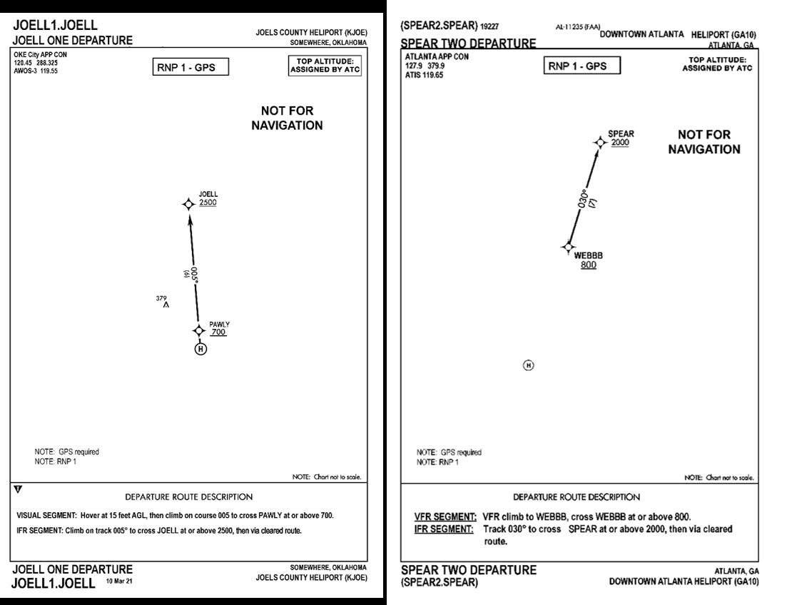
Departure Procedures
- When departing from a location on a point-in-space (PinS) SID with a visual segment indicated and the departure instruction describes the visual segment the aircraft must cross the initial departure fix (IDF) outbound at-or-above the altitude depicted on the chart. The helicopter will initially establish a hover at or above the heliport crossing height (HCH) specified on the chart. The HCH specifies a minimum hover height to begin the climb to assist in avoiding obstacles. The helicopter will leave the departure location on the published outbound heading/course specified, climbing at least 400 ft/per NM (or as depicted on the chart), remaining clear of clouds, crossing at or above the IDF altitude specified, prior to proceeding outbound on the procedure. For example the chart may include these instructions: “Hover at 15 ft AGL, then climb on track 005, remaining clear of clouds, to cross PAWLY at or above 700.”
- When flying a PinS SID procedure containing a segment with instructions to “proceed VFR,” the pilot must keep the aircraft clear of the clouds and cross the IDF outbound at or above the altitude depicted. Departure procedures that support multiple departure locations will have a Proceed VFR segment leading to the IDF. The chart will provide a bearing and distance to the IDF from the heliport. That bearing and distance are for pilot orientation purposes only and are not a required procedure track. The helicopter will leave the departure location via pilot navigation in order to align with the departure route and comply with the altitude specified at the IDF. For example, the chart may include these instructions: “VFR Climb to WEBBB, Cross WEBBB at or above 800.”
-
Once the aircraft reaches the IDF, the aircraft should proceed out the described route as specified on the chart, crossing each consecutive fix at or above the indicated altitude(s) until reaching the end of the departure or as directed by ATC.
FIG 10-1-1
Departure Charts