You have 0 items in your cart

FAR/AIM
>
Aeronautical Information Manual
>
Chapter 4. Air Traffic Control
>
Section 3. Airport Operations
Section 3. Airport Operations
-
General
Increased traffic congestion, aircraft in climb and descent attitudes, and pilot preoccupation with cockpit duties are some factors that increase the hazardous accident potential near the airport. The situation is further compounded when the weather is marginal, that is, just meeting VFR requirements. Pilots must be particularly alert when operating in the vicinity of an airport. This section defines some rules, practices, and procedures that pilots should be familiar with and adhere to for safe airport operations.
-
Airports with an Operating Control Tower
- When operating at an airport where traffic control is being exercised by a control tower, pilots are required to maintain two-way radio contact with the tower while operating within the Class B, Class C, and Class D surface area unless the tower authorizes otherwise. Initial callup should be made about 15 miles from the airport. Unless there is a good reason to leave the tower frequency before exiting the Class B, Class C, and Class D surface areas, it is a good operating practice to remain on the tower frequency for the purpose of receiving traffic information. In the interest of reducing tower frequency congestion, pilots are reminded that it is not necessary to request permission to leave the tower frequency once outside of Class B, Class C, and Class D surface areas. Not all airports with an operating control tower will have Class D airspace. These airports do not have weather reporting which is a requirement for surface based controlled airspace, previously known as a control zone. The controlled airspace over these airports will normally begin at 700 feet or 1,200 feet above ground level and can be determined from the visual aeronautical charts. Pilots are expected to use good operating practices and communicate with the control tower as described in this section.
-
When necessary, the tower controller will issue clearances or other information for aircraft to generally follow the desired flight path (traffic patterns) when flying in Class B, Class C, and Class D surface areas and the proper taxi routes when operating on the ground. If not otherwise authorized or directed by the tower, pilots of fixed-wing aircraft approaching to land must circle the airport to the left. Pilots approaching to land in a helicopter must avoid the flow of fixed-wing traffic. However, in all instances, an appropriate clearance must be received from the tower before landing.
FIG 4-3-1
Components of a Traffic Pattern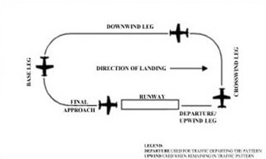
NOTE-
This diagram is intended only to illustrate terminology used in identifying various components of a traffic pattern. It should not be used as a reference or guide on how to enter a traffic pattern.
-
The following terminology for the various components of a traffic pattern has been adopted as standard for use by control towers and pilots (See FIG 4-3-1):
- Departure. The flight path that begins after takeoff and continues straight ahead along the extended runway centerline. The departure climb continues until reaching a point at least 1/2 mile beyond the departure end of the runway and within 300 feet of the traffic pattern altitude.
- Upwind leg. A flight path that begins after departure and continues straight ahead along the extended runway centerline. Upwind leg is an extension of departure and is used when issuing control instructions for separation, spacing, or sequencing.
- Crosswind leg. A flight path at right angles to the landing runway off its takeoff end.
- Downwind leg. A flight path parallel to the landing runway in the opposite direction of landing.
- Base leg. A flight path at right angles to the landing runway off its approach end and extending from the downwind leg to the intersection of the extended runway centerline.
- Final approach. A flight path in the direction of landing along the extended runway centerline from the base leg to the runway.
-
Many towers are equipped with a tower radar display. The radar uses are intended to enhance the effectiveness and efficiency of the local control, or tower, position. They are not intended to provide radar services or benefits to pilots except as they may accrue through a more efficient tower operation. The four basic uses are:
- To determine an aircraft's exact location.This is accomplished by radar identifying the VFR aircraft through any of the techniques available to a radar position, such as having the aircraft squawk ident. Once identified, the aircraft's position and spatial relationship to other aircraft can be quickly determined, and standard instructions regarding VFR operation in Class B, Class C, and Class D surface areas will be issued. Once initial radar identification of a VFR aircraft has been established and the appropriate instructions have been issued, radar monitoring may be discontinued; the reason being that the local controller's primary means of surveillance in VFR conditions is visually scanning the airport and local area.
- To provide radar traffic advisories. Radar traffic advisories may be provided to the extent that the local controller is able to monitor the radar display. Local control has primary control responsibilities to the aircraft operating on the runways, which will normally supersede radar monitoring duties.
-
To provide a direction or suggested heading. The local controller may provide pilots flying VFR with generalized instructions which will facilitate operations; e.g., “PROCEED SOUTHWESTBOUND, ENTER A RIGHT DOWNWIND RUNWAY THREE ZERO,” or provide a suggested heading to establish radar identification or as an advisory aid to navigation; e.g., “SUGGESTED HEADING TWO TWO ZERO, FOR RADAR IDENTIFICATION.” In both cases, the instructions are advisory aids to the pilot flying VFR and are not radar vectors.
NOTE-
Pilots have complete discretion regarding acceptance of the suggested headings or directions and have sole responsibility for seeing and avoiding other aircraft.
-
To provide information and instructions to aircraft operating within Class B, Class C, and Class D surface areas. In an example of this situation, the local controller would use the radar to advise a pilot on an extended downwind when to turn base leg.
NOTE-
The above tower radar applications are intended to augment the standard functions of the local control position. There is no controller requirement to maintain constant radar identification. In fact, such a requirement could compromise the local controller's ability to visually scan the airport and local area to meet FAA responsibilities to the aircraft operating on the runways and within the Class B, Class C, and Class D surface areas. Normally, pilots will not be advised of being in radar contact since that continued status cannot be guaranteed and since the purpose of the radar identification is not to establish a link for the provision of radar services.
- A few of the radar equipped towers are authorized to use the radar to ensure separation between aircraft in specific situations, while still others may function as limited radar approach controls. The various radar uses are strictly a function of FAA operational need. The facilities may be indistinguishable to pilots since they are all referred to as tower and no publication lists the degree of radar use. Therefore, when in communication with a tower controller who may have radar available, do not assume that constant radar monitoring and complete ATC radar services are being provided.
-
Traffic Patterns
-
It is recommended that aircraft enter the airport traffic pattern at one of the following altitudes listed below. These altitudes should be maintained unless another traffic pattern altitude is published in the Chart Supplement or unless otherwise required by the applicable distance from cloud criteria (14 CFR section 91.155). (See FIG 4-3-2 and FIG 4-3-3):
- Propeller-driven aircraft enter the traffic pattern at 1,000 feet above ground level (AGL).
- Large and turbine-powered aircraft enter the traffic pattern at an altitude of not less than 1,500 feet AGL or 500 feet above the established pattern altitude.
- Helicopters operating in the traffic pattern may fly a pattern similar to the fixed-wing aircraft pattern, but at a lower altitude (500 AGL) and closer to the runway. This pattern may be on the opposite side of the runway from fixed-wing traffic when airspeed requires or for practice power-off landings (autorotation) and if local policy permits. Landings not to the runway must avoid the flow of fixed wing traffic.
- A pilot may vary the size of the traffic pattern depending on the aircraft's performance characteristics. Pilots of en route aircraft should be constantly alert for aircraft in traffic patterns and avoid these areas whenever possible.
- Unless otherwise indicated, all turns in the traffic pattern must be made to the left, except for helicopters, as applicable.
-
On Sectional, Aeronautical, and VFR Terminal Area Charts, right traffic patterns are indicated at public-use and joint-use airports with the abbreviation “RP” (for Right Pattern), followed by the appropriate runway number(s) at the bottom of the airport data block.
EXAMPLE-
RP 9, 18, 22R
NOTE-
- Pilots are encouraged to use the standard traffic pattern. However, those pilots who choose to execute a straight-in approach, maneuvering for and execution of the approach should not disrupt the flow of arriving and departing traffic. Likewise, pilots operating in the traffic pattern should be alert at all times for aircraft executing straight-in approaches.
REFERENCE-
AC 90-66, Non-Towered Airport Flight Operations.
- *RP indicates special conditions exist and refers pilots to the Chart Supplement.
- Right traffic patterns are not shown at airports with full-time control towers.
-
Wind conditions affect all airplanes in varying degrees. Figure 4-3-4 is an example of a chart used to determine the headwind, crosswind, and tailwind components based on wind direction and velocity relative to the runway. Pilots should refer to similar information provided by the aircraft manufacturer when determining these wind components.
FIG 4-3-2
Traffic Pattern Operations Single Runway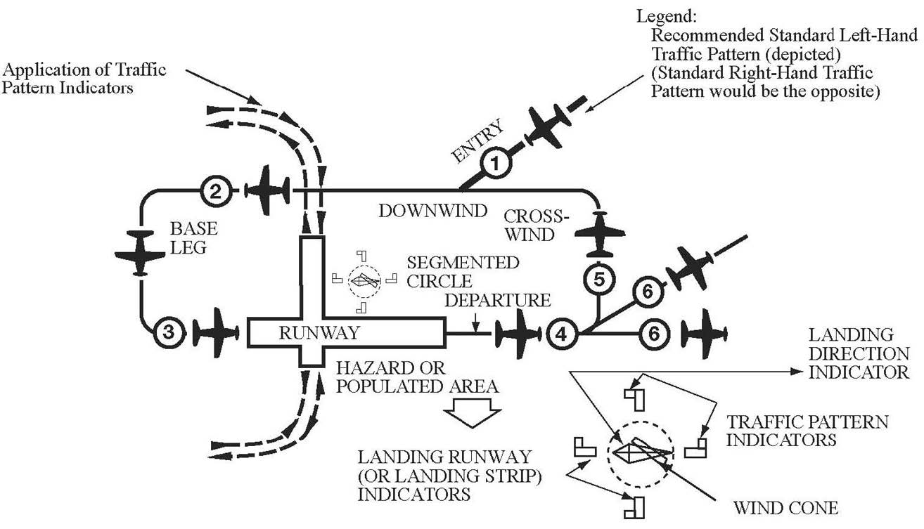
EXAMPLE-
Key to traffic pattern operations- Enter pattern in level flight, abeam the midpoint of the runway, at pattern altitude.
- Maintain pattern altitude until abeam approach end of the landing runway on downwind leg.
- Complete turn to final at least 1/4 mile from the runway.
- Continue straight ahead until beyond departure end of runway.
- If remaining in the traffic pattern, commence turn to crosswind leg beyond the departure end of the runway within 300 feet of pattern altitude.
- If departing the traffic pattern, continue straight out, or exit with a 45 degree turn (to the left when in a left-hand traffic pattern; to the right when in a right-hand traffic pattern) beyond the departure end of the runway, after reaching pattern altitude.
FIG 4-3-3
Traffic Pattern Operations Parallel Runways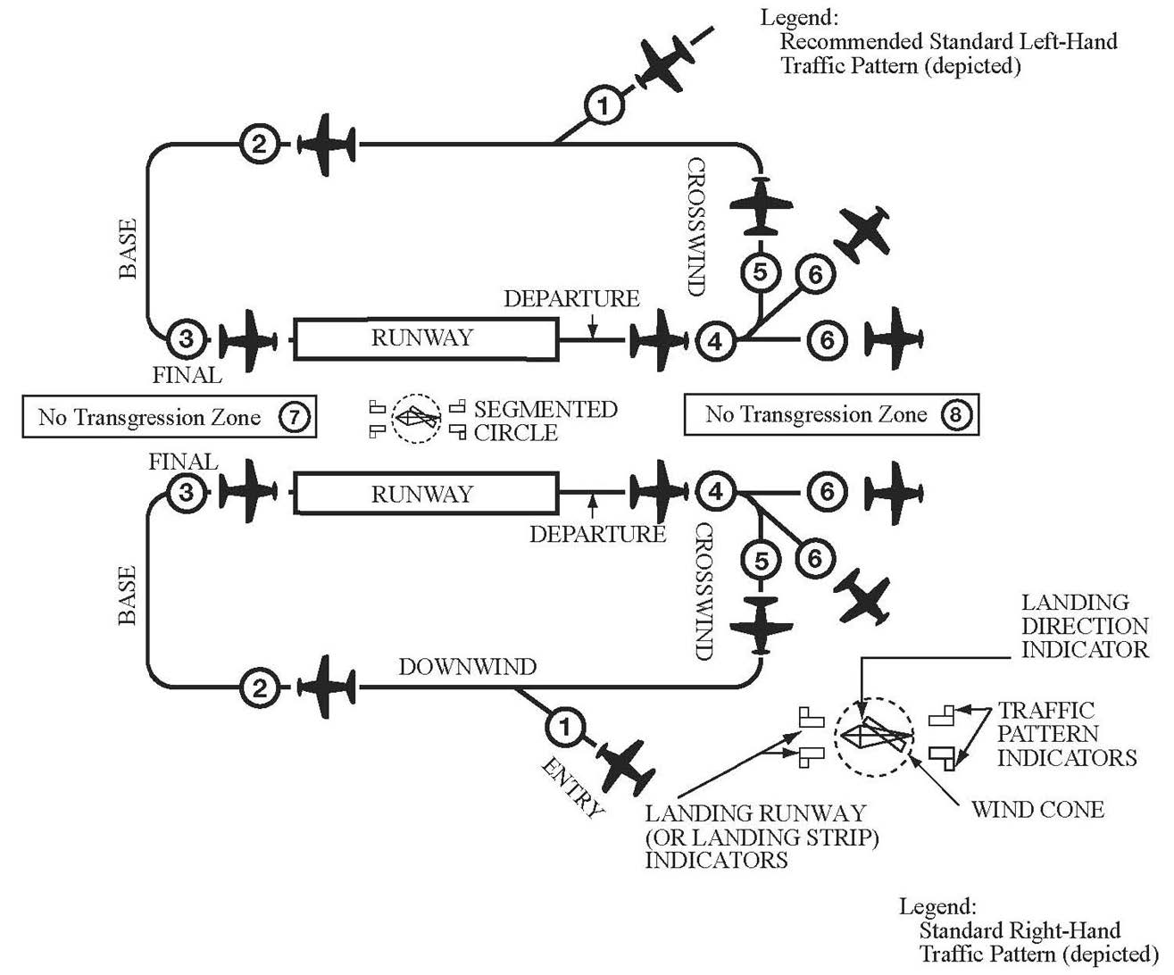
EXAMPLE-
Key to traffic pattern operations- Enter pattern in level flight, abeam the midpoint of the runway, at pattern altitude.
- Maintain pattern altitude until abeam approach end of the landing runway on downwind leg.
- Complete turn to final at least 1/4 mile from the runway.
- Continue straight ahead until beyond departure end of runway.
- If remaining in the traffic pattern, commence turn to crosswind leg beyond the departure end of the runway within 300 feet of pattern altitude.
- If departing the traffic pattern, continue straight out, or exit with a 45 degree turn (to the left when in a left-hand traffic pattern; to the right when in a right-hand traffic pattern) beyond the departure end of the runway, after reaching pattern altitude.
- Do not overshoot final or continue on a track which will penetrate the final approach of the parallel runway.
- Do not continue on a track which will penetrate the departure path of the parallel runway.
FIG 4-3-4
Headwind/Tailwind/Crosswind Component Calculator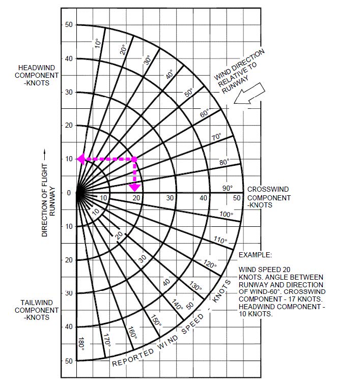
-
It is recommended that aircraft enter the airport traffic pattern at one of the following altitudes listed below. These altitudes should be maintained unless another traffic pattern altitude is published in the Chart Supplement or unless otherwise required by the applicable distance from cloud criteria (14 CFR section 91.155). (See FIG 4-3-2 and FIG 4-3-3):
-
Visual Indicators at Airports Without an Operating Control Tower
-
At those airports without an operating control tower, a segmented circle visual indicator system, if installed, is designed to provide traffic pattern information.
REFERENCE-
AIM, Para 4-1-9, Traffic Advisory Practices at Airports Without Operating Control Towers.
-
The segmented circle system consists of the following components:
- The segmented circle. Located in a position affording maximum visibility to pilots in the air and on the ground and providing a centralized location for other elements of the system.
- The wind direction indicator. A wind cone, wind sock, or wind tee installed near the operational runway to indicate wind direction. The large end of the wind cone/wind sock points into the wind as does the large end (cross bar) of the wind tee. In lieu of a tetrahedron and where a wind sock or wind cone is collocated with a wind tee, the wind tee may be manually aligned with the runway in use to indicate landing direction. These signaling devices may be located in the center of the segmented circle and may be lighted for night use. Pilots are cautioned against using a tetrahedron to indicate wind direction.
- The landing direction indicator. A tetrahedron is installed when conditions at the airport warrant its use. It may be used to indicate the direction of landings and takeoffs. A tetrahedron may be located at the center of a segmented circle and may be lighted for night operations. The small end of the tetrahedron points in the direction of landing. Pilots are cautioned against using a tetrahedron for any purpose other than as an indicator of landing direction. Further, pilots should use extreme caution when making runway selection by use of a tetrahedron in very light or calm wind conditions as the tetrahedron may not be aligned with the designated calm-wind runway. At airports with control towers, the tetrahedron should only be referenced when the control tower is not in operation. Tower instructions supersede tetrahedron indications.
- Landing strip indicators. Installed in pairs as shown in the segmented circle diagram and used to show the alignment of landing strips.
- Traffic pattern indicators. Arranged in pairs in conjunction with landing strip indicators and used to indicate the direction of turns when there is a variation from the normal left traffic pattern. (If there is no segmented circle installed at the airport, traffic pattern indicators may be installed on or near the end of the runway.)
- Preparatory to landing at an airport without a control tower, or when the control tower is not in operation, pilots should concern themselves with the indicator for the approach end of the runway to be used. When approaching for landing, all turns must be made to the left unless a traffic pattern indicator indicates that turns should be made to the right. If the pilot will mentally enlarge the indicator for the runway to be used, the base and final approach legs of the traffic pattern to be flown immediately become apparent. Similar treatment of the indicator at the departure end of the runway will clearly indicate the direction of turn after takeoff.
- When two or more aircraft are approaching an airport for the purpose of landing, the pilot of the aircraft at the lower altitude has the right-of-way over the pilot of the aircraft at the higher altitude. However, the pilot operating at the lower altitude should not take advantage of another aircraft, which is on final approach to land, by cutting in front of, or overtaking that aircraft.
-
At those airports without an operating control tower, a segmented circle visual indicator system, if installed, is designed to provide traffic pattern information.
-
Unexpected Maneuvers in the Airport Traffic Pattern
There have been several incidents in the vicinity of controlled airports that were caused primarily by aircraft executing unexpected maneuvers. ATC service is based upon observed or known traffic and airport conditions. Controllers establish the sequence of arriving and departing aircraft by requiring them to adjust flight as necessary to achieve proper spacing. These adjustments can only be based on observed traffic, accurate pilot reports, and anticipated aircraft maneuvers. Pilots are expected to cooperate so as to preclude disrupting traffic flows or creating conflicting patterns. The pilot-in-command of an aircraft is directly responsible for and is the final authority as to the operation of the aircraft. On occasion it may be necessary for pilots to maneuver their aircraft to maintain spacing with the traffic they have been sequenced to follow. The controller can anticipate minor maneuvering such as shallow “S” turns. The controller cannot, however, anticipate a major maneuver such as a 360 degree turn. If a pilot makes a 360 degree turn after obtaining a landing sequence, the result is usually a gap in the landing interval and, more importantly, it causes a chain reaction which may result in a conflict with following traffic and an interruption of the sequence established by the tower or approach controller. Should a pilot decide to make maneuvering turns to maintain spacing behind a preceding aircraft, the pilot should always advise the controller if at all possible. Except when requested by the controller or in emergency situations, a 360 degree turn should never be executed in the traffic pattern or when receiving radar service without first advising the controller.
-
Use of Runways/Declared Distances
-
Runways are identified by numbers that indicate the nearest 10-degree increment of the azimuth of the runway centerline. For example, where the magnetic azimuth is 183 degrees, the runway designation would be 18; for a magnetic azimuth of 87 degrees, the runway designation would be 9. For a magnetic azimuth ending in the number 5, such as 185, the runway designation could be either 18 or 19. Wind direction issued by the tower is also magnetic and wind velocity is in knots.
NOTE-
- At airports with multiple parallel runways whose magnetic azimuths are identical, each runway number will be supplemented by a letter and shown from left to right when viewed from the direction of approach.
- When multiple parallel runways at the same airport are separated by a large distance, such as by a central terminal or several terminals, the runways may be designated as non-parallel runways to avoid pilot confusion.
REFERENCE-
AC 150/5340-1, Standards for Airport Markings, Para 2.3.5, Characteristics.
-
Airport proprietors are responsible for taking the lead in local aviation noise control. Accordingly, they may propose specific noise abatement plans to the FAA. If approved, these plans are applied in the form of Formal or Informal Runway Use Programs for noise abatement purposes.
REFERENCE-
P/CG Term - RUNWAY USE PROGRAM.
-
ATC will assign the runway/s most nearly aligned with the wind when 5 knots or more, or the “calm wind” runway when less than 5 knots unless:
- Use of another runway is operationally advantageous, or
-
A Runway Use Program is in effect.
NOTE-
Tailwind and crosswind considerations take precedence over delay/capacity considerations, and noise abatement operations/procedures.
REFERENCE-
FAA Order JO 7110.65, Para 3-5-1, Selection.
-
ATC will assign the runway/s most nearly aligned with the wind when 5 knots or more, or the “calm wind” runway when less than 5 knots unless:
-
If a pilot prefers to use a runway different from that specified, the pilot is expected to advise ATC. ATC may honor such requests as soon as is operationally practicable. ATC will advise pilots when the requested runway is noise sensitive. When use of a runway other than the one assigned is requested, pilot cooperation is encouraged to preclude disruption of traffic flows or the creation of conflicting patterns.
REFERENCE-
FAA Order JO 7110.65, Para 3-5-1, Selection.
-
Declared Distances.
- Declared distances for a runway represent the maximum distances available and suitable for meeting takeoff and landing distance performance requirements. These distances are determined in accordance with FAA runway design standards by adding to the physical length of paved runway any clearway or stopway and subtracting from that sum any lengths necessary to obtain the standard runway safety areas, runway object free areas, or runway protection zones. As a result of these additions and subtractions, the declared distances for a runway may be more or less than the physical length of the runway as depicted on aeronautical charts and related publications, or available in electronic navigation databases provided by either the U.S. Government or commercial companies.
-
All 14 CFR part 139 airports report declared distances for each runway. Other airports may also report declared distances for a runway if necessary to meet runway design standards or to indicate the presence of a clearway or stopway. Where reported, declared distances for each runway end are published in the Chart Supplement. For runways without published declared distances, the declared distances may be assumed to be equal to the physical length of the runway unless there is a displaced landing threshold, in which case the Landing Distance Available (LDA) is shortened by the amount of the threshold displacement.
NOTE-
A symbol
 is shown on U.S. Government charts to indicate that runway declared distance information is available (See appropriate Chart Supplement, Chart Supplement Alaska or Pacific).
-
The FAA uses the following definitions for runway declared distances (See FIG 4-3-5):
REFERENCE-
P/CG Term - “ACCELERATE-STOP DISTANCE AVAILABLE,” “LANDING DISTANCE AVAILABLE,” “TAKEOFF DISTANCE AVAILABLE,” “TAKEOFF RUN AVAILABLE,” ” STOPWAY,” AND “CLEARWAY.”
-
Takeoff Run Available (TORA) - The runway length declared available and suitable for the ground run of an airplane taking off.
The TORA is typically the physical length of the runway, but it may be shorter than the runway length if necessary to satisfy runway design standards. For example, the TORA may be shorter than the runway length if a portion of the runway must be used to satisfy runway protection zone requirements. -
Takeoff Distance Available (TODA) - The takeoff run available plus the length of any remaining runway or clearway beyond the far end of the takeoff run available.
The TODA is the distance declared available for satisfying takeoff distance requirements for airplanes where the certification and operating rules and available performance data allow for the consideration of a clearway in takeoff performance computations.NOTE-
The length of any available clearway will be included in the TODA published in the entry for that runway end within the Chart Supplement.
-
Accelerate-Stop Distance Available (ASDA) - The runway plus stopway length declared available and suitable for the acceleration and deceleration of an airplane aborting a takeoff.
The ASDA may be longer than the physical length of the runway when a stopway has been designated available by the airport operator, or it may be shorter than the physical length of the runway if necessary to use a portion of the runway to satisfy runway design standards; for example, where the airport operator uses a portion of the runway to achieve the runway safety area requirement. ASDA is the distance used to satisfy the airplane accelerate-stop distance performance requirements where the certification and operating rules require accelerate-stop distance computations.NOTE-
The length of any available stopway will be included in the ASDA published in the entry for that runway end within the Chart Supplement.
-
Landing Distance Available (LDA) - The runway length declared available and suitable for a landing airplane.
The LDA may be less than the physical length of the runway or the length of the runway remaining beyond a displaced threshold if necessary to satisfy runway design standards;for example, where the airport operator uses a portion of the runway to achieve the runway safety area requirement.
Although some runway elements (such as stopway length and clearway length) may be available information, pilots must use the declared distances determined by the airport operator and not attempt to independently calculate declared distances by adding those elements to the reported physical length of the runway.
-
Takeoff Run Available (TORA) - The runway length declared available and suitable for the ground run of an airplane taking off.
- The airplane operating rules and/or the airplane operating limitations establish minimum distance requirements for takeoff and landing and are based on performance data supplied in the Airplane Flight Manual or Pilot's Operating Handbook. The minimum distances required for takeoff and landing obtained either in planning prior to takeoff or in performance assessments conducted at the time of landing must fall within the applicable declared distances before the pilot can accept that runway for takeoff or landing.
-
Runway design standards may impose restrictions on the amount of runway available for use in takeoff and landing that are not apparent from the reported physical length of the runway or from runway markings and lighting. The runway elements of Runway Safety Area (RSA), Runway Object Free Area (ROFA), and Runway Protection Zone (RPZ) may reduce a runway's declared distances to less than the physical length of the runway at geographically constrained airports (See FIG 4-3-6). When considering the amount of runway available for use in takeoff or landing performance calculations, the declared distances published for a runway must always be used in lieu of the runway's physical length.
REFERENCE-
AC 150/5300-13, Airport Design.
-
While some runway elements associated with declared distances may be identifiable through runway markings or lighting (for example, a displaced threshold or a stopway), the individual declared distance limits are not marked or otherwise identified on the runway. An aircraft is not prohibited from operating beyond a declared distance limit during the takeoff, landing, or taxi operation provided the runway surface is appropriately marked as usable runway (See FIG 4-3-6). The following examples clarify the intent of this paragraph.
REFERENCE-
AIM, Para 2-3-3, Runway Markings.
AC 150/5340-1, Standards for Airport Markings.EXAMPLE-
- The declared LDA for runway 9 must be used when showing compliance with the landing distance requirements of the applicable airplane operating rules and/or airplane operating limitations or when making a before landing performance assessment. The LDA is less than the physical runway length, not only because of the displaced threshold, but also because of the subtractions necessary to meet the RSA beyond the far end of the runway. However, during the actual landing operation, it is permissible for the airplane to roll beyond the unmarked end of the LDA.
- The declared ASDA for runway 9 must be used when showing compliance with the accelerate-stop distance requirements of the applicable airplane operating rules and/or airplane operating limitations. The ASDA is less than the physical length of the runway due to subtractions necessary to achieve the full RSA requirement. However, in the event of an aborted takeoff, it is permissible for the airplane to roll beyond the unmarked end of the ASDA as it is brought to a full-stop on the remaining usable runway.
FIG 4-3-5
Declared Distances with Full-Standard Runway Safety Areas, Runway Object Free Areas, and Runway Protection Zones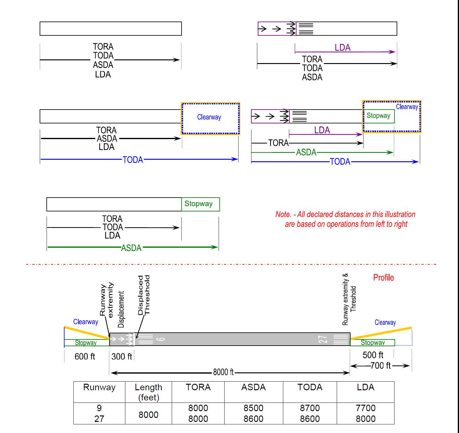
FIG 4-3-6
Effects of a Geographical Constraint on a Runway's Declared Distances
NOTE-
A runway's RSA begins a set distance prior to the threshold and will extend a set distance beyond the end of the runway depending on the runway's design criteria. If these required lengths cannot be achieved, the ASDA and/or LDA will be reduced as necessary to obtain the required lengths to the extent practicable.
-
The FAA uses the following definitions for runway declared distances (See FIG 4-3-5):
-
Runways are identified by numbers that indicate the nearest 10-degree increment of the azimuth of the runway centerline. For example, where the magnetic azimuth is 183 degrees, the runway designation would be 18; for a magnetic azimuth of 87 degrees, the runway designation would be 9. For a magnetic azimuth ending in the number 5, such as 185, the runway designation could be either 18 or 19. Wind direction issued by the tower is also magnetic and wind velocity is in knots.
-
Low Level Wind Shear/Microburst Detection Systems
Low Level Wind Shear Alert System (LLWAS), Terminal Doppler Weather Radar (TDWR), Weather Systems Processor (WSP), and Integrated Terminal Weather System (ITWS) display information on hazardous wind shear and microburst activity in the vicinity of an airport to air traffic controllers who relay this information to pilots.
-
LLWAS provides wind shear alert and gust front information but does not provide microburst alerts. The LLWAS is designed to detect low level wind shear conditions around the periphery of an airport. It does not detect wind shear beyond that limitation. Controllers will provide this information to pilots by giving the pilot the airport wind followed by the boundary wind.
EXAMPLE-
Wind shear alert, airport wind 230 at 8, south boundary wind 170 at 20.
-
LLWAS “network expansion,” (LLWAS NE) and LLWAS Relocation/Sustainment (LLWAS-RS) are systems integrated with TDWR. These systems provide the capability of detecting microburst alerts and wind shear alerts. Controllers will issue the appropriate wind shear alerts or microburst alerts. In some of these systems controllers also have the ability to issue wind information oriented to the threshold or departure end of the runway.
EXAMPLE-
Runway 17 arrival microburst alert, 40 knot loss 3 mile final.
REFERENCE-
AIM, Para 7-1-24, Microbursts.
- More advanced systems are in the field or being developed such as ITWS. ITWS provides alerts for microbursts, wind shear, and significant thunderstorm activity. ITWS displays wind information oriented to the threshold or departure end of the runway.
- The WSP provides weather processor enhancements to selected Airport Surveillance Radar (ASR)-9 facilities. The WSP provides Air Traffic with detection and alerting of hazardous weather such as wind shear, microbursts, and significant thunderstorm activity. The WSP displays terminal area 6 level weather, storm cell locations and movement, as well as the location and predicted future position and intensity of wind shifts that may affect airport operations. Controllers will receive and issue alerts based on Areas Noted for Attention (ARENA). An ARENA extends on the runway center line from a 3 mile final to the runway to a 2 mile departure.
- An airport equipped with the LLWAS, ITWS, or WSP is so indicated in the Chart Supplement under Weather Data Sources for that particular airport.
-
LLWAS provides wind shear alert and gust front information but does not provide microburst alerts. The LLWAS is designed to detect low level wind shear conditions around the periphery of an airport. It does not detect wind shear beyond that limitation. Controllers will provide this information to pilots by giving the pilot the airport wind followed by the boundary wind.
-
Braking Action Reports and Advisories
- When available, ATC furnishes pilots the quality of braking action received from pilots. The quality of braking action is described by the terms “good,” “good to medium,” “medium,” “medium to poor,” “poor,” and “nil.” When pilots report the quality of braking action by using the terms noted above, they should use descriptive terms that are easily understood, such as, “braking action poor the first/last half of the runway,” together with the particular type of aircraft.
-
FICON NOTAMs will provide contaminant measurements for paved runways; however, a FICON NOTAM for braking action will only be used for non-paved runway surfaces, taxiways, and aprons. These NOTAMs are classified according to the most critical term (“good to medium,” “medium,” “medium to poor,” and “poor”).
- FICON NOTAM reporting of a braking condition for paved runway surfaces is not permissible by Federally Obligated Airports or those airports certificated under 14 CFR part 139.
- A “NIL” braking condition at these airports must be mitigated by closure of the affected surface. Do not include the type of vehicle in the FICON NOTAM.
- When tower controllers receive runway braking action reports which include the terms medium, poor, or nil, or whenever weather conditions are conducive to deteriorating or rapidly changing runway braking conditions, the tower will include on the ATIS broadcast the statement, “BRAKING ACTION ADVISORIES ARE IN EFFECT.”
- During the time that braking action advisories are in effect, ATC will issue the most recent braking action report for the runway in use to each arriving and departing aircraft. Pilots should be prepared for deteriorating braking conditions and should request current runway condition information if not issued by controllers. Pilots should also be prepared to provide a descriptive runway condition report to controllers after landing.
-
Runway Condition Reports
- Aircraft braking coefficient is dependent upon the surface friction between the tires on the aircraft wheels and the pavement surface. Less friction means less aircraft braking coefficient and less aircraft braking response.
-
Runway condition code (RwyCC) values range from 1 (poor) to 6 (dry). For frozen contaminants on runway surfaces, a runway condition code reading of 4 indicates the level when braking deceleration or directional control is between good and medium.
NOTE-
A RwyCC of “0” is used to delineate a braking action report of NIL and is prohibited from being reported in a FICON NOTAM.
-
Airport management should conduct runway condition assessments on wet runways or runways covered with compacted snow and/or ice.
-
Numerical readings may be obtained by using the Runway Condition Assessment Matrix (RCAM). The RCAM provides the airport operator with data to complete the report that includes the following:
- Runway(s) in use
- Time of the assessment
- Runway condition codes for each zone (touchdown, mid-point, roll-out)
- Pilot-reported braking action report (if available)
- The contaminant (for example, wet snow, dry snow, slush, ice, etc.)
-
Assessments for each zone (see 4-3-9c1(c)) will be issued in the direction of takeoff and landing on the runway, ranging from “1” to “6” to describe contaminated surfaces.
NOTE-
A RwyCC of “0” is used to delineate a braking action report of NIL and is prohibited from being reported in a FICON NOTAM.
- When any 1 or more runway condition codes are reported as less than 6, airport management must notify ATC for dissemination to pilots.
- Controllers will not issue runway condition codes when all 3 segments of a runway are reporting values of 6.
-
Numerical readings may be obtained by using the Runway Condition Assessment Matrix (RCAM). The RCAM provides the airport operator with data to complete the report that includes the following:
- When runway condition code reports are provided by airport management, the ATC facility providing approach control or local airport advisory must provide the report to all pilots.
- Pilots should use runway condition code information with other knowledge including aircraft performance characteristics, type, and weight, previous experience, wind conditions, and aircraft tire type (such as bias ply vs. radial constructed) to determine runway suitability.
-
The Runway Condition Assessment Matrix identifies the descriptive terms “good,” “good to medium,” “medium,” “medium to poor,” “poor,” and “nil” used in braking action reports.
REFERENCE-
Advisory Circular AC 91-79, Mitigating the Risks of a Runway Overrun Upon Landing, Appendix 1.
FIG 4-3-7
Runway Condition Assessment Matrix (RCAM)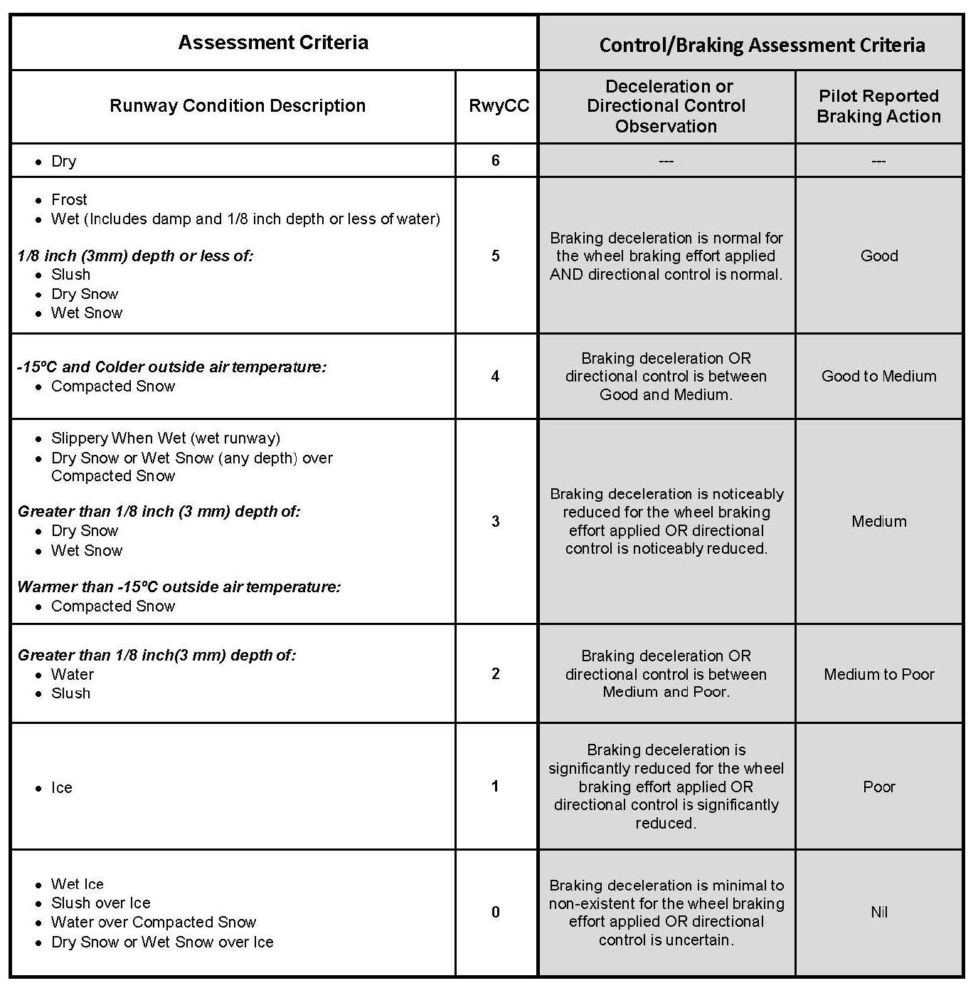
-
Intersection Takeoffs
- In order to enhance airport capacities, reduce taxiing distances, minimize departure delays, and provide for more efficient movement of air traffic, controllers may initiate intersection takeoffs as well as approve them when the pilot requests. If for ANY reason a pilot prefers to use a different intersection or the full length of the runway or desires to obtain the distance between the intersection and the runway end, THE PILOT IS EXPECTED TO INFORM ATC ACCORDINGLY.
-
Pilots are expected to assess the suitability of an intersection for use at takeoff during their preflight planning. They must consider the resultant length reduction to the published runway length and to the published declared distances from the intersection intended to be used for takeoff. The minimum runway required for takeoff must fall within the reduced runway length and the reduced declared distances before the intersection can be accepted for takeoff.
REFERENCE-
AIM, Para 4-3-6, Use of Runways/Declared Distances.
-
Controllers will issue the measured distance from the intersection to the runway end rounded “down” to the nearest 50 feet to any pilot who requests and to all military aircraft, unless use of the intersection is covered in appropriate directives. Controllers, however, will not be able to inform pilots of the distance from the intersection to the end of any of the published declared distances.
REFERENCE-
FAA Order JO 7110.65, Para 3-7-1, Ground Traffic Movement.
- An aircraft is expected to taxi to (but not onto) the end of the assigned runway unless prior approval for an intersection departure is received from ground control.
-
Pilots should state their position on the airport when calling the tower for takeoff from a runway intersection.
EXAMPLE-
Cleveland Tower, Apache Three Seven Two Two Papa, at the intersection of taxiway Oscar and runway two three right, ready for departure.
- Controllers are required to separate small aircraft that are departing from an intersection on the same runway (same or opposite direction) behind a large nonheavy aircraft (except B757), by ensuring that at least a 3-minute interval exists between the time the preceding large aircraft has taken off and the succeeding small aircraft begins takeoff roll. The 3-minute separation requirement will also be applied to small aircraft with a maximum certificated takeoff weight of 12,500 pounds or less departing behind a small aircraft with a maximum certificated takeoff weight of more than 12,500 pounds. To inform the pilot of the required 3-minute hold, the controller will state, “Hold for wake turbulence.” If after considering wake turbulence hazards, the pilot feels that a lesser time interval is appropriate, the pilot may request a waiver to the 3-minute interval. To initiate such a request, simply say “Request waiver to 3-minute interval” or a similar statement. Controllers may then issue a takeoff clearance if other traffic permits, since the pilot has accepted the responsibility for wake turbulence separation.
- The 3-minute interval is not required when the intersection is 500 feet or less from the departure point of the preceding aircraft and both aircraft are taking off in the same direction. Controllers may permit the small aircraft to alter course after takeoff to avoid the flight path of the preceding departure.
- A 4-minute interval is mandatory for small, large, and heavy aircraft behind a super aircraft. The 3-minute interval is mandatory behind a heavy aircraft in all cases, and for small aircraft behind a B757.
-
Pilot Responsibilities When Conducting Land and Hold Short Operations (LAHSO)
- LAHSO is an acronym for “Land and Hold Short Operations.” These operations include landing and holding short of an intersecting runway, an intersecting taxiway, or some other designated point on a runway other than an intersecting runway or taxiway. (See FIG 4-3-8, FIG 4-3-9, FIG 4-3-10.)
-
Pilot Responsibilities and Basic Procedures.
- LAHSO is an air traffic control procedure that requires pilot participation to balance the needs for increased airport capacity and system efficiency, consistent with safety. This procedure can be done safely provided pilots and controllers are knowledgeable and understand their responsibilities. The following paragraphs outline specific pilot/operator responsibilities when conducting LAHSO.
- At controlled airports, air traffic may clear a pilot to land and hold short. Pilots may accept such a clearance provided that the pilot-in-command determines that the aircraft can safely land and stop within the Available Landing Distance (ALD). ALD data are published in the Chart Supplementand in the U.S.Terminal Procedures Publications.Controllers will also provide ALD data upon request. Student pilots or pilots not familiar with LAHSO should not participate in the program.
- The pilot-in-command has the final authority to accept or decline any land and hold short clearance. The safety and operation of the aircraft remain the responsibility of the pilot. Pilots are expected to decline a LAHSO clearance if they determine it will compromise safety.
-
To conduct LAHSO, pilots should become familiar with all available information concerning LAHSO at their destination airport. Pilots should have, readily available, the published ALD and runway slope information for all LAHSO runway combinations at each airport of intended landing. Additionally, knowledge about landing performance data permits the pilot to readily determine that the ALD for the assigned runway is sufficient for safe LAHSO. As part of a pilot's preflight planning process, pilots should determine if their destination airport has LAHSO. If so, their preflight planning process should include an assessment of which LAHSO combinations would work for them given their aircraft's required landing distance. Good pilot decision making is knowing in advance whether one can accept a LAHSO clearance if offered.
FIG 4-3-8
Land and Hold Short of an Intersecting Runway
EXAMPLE-
FIG 4-3-10 - holding short at a designated point may be required to avoid conflicts with the runway safety area/flight path of a nearby runway.
NOTE-
Each figure shows the approximate location of LAHSO markings, signage, and in-pavement lighting when installed.
REFERENCE-
AIM, Chapter 2, Aeronautical Lighting and Other Airport Visual Aids.
FIG 4-3-9
Land and Hold Short of an Intersecting Taxiway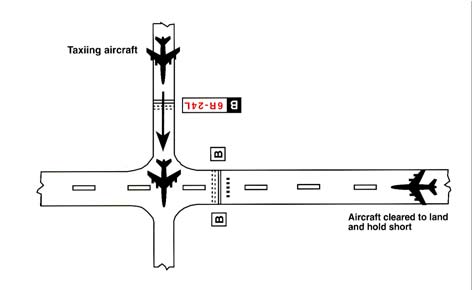
FIG 4-3-10
Land and Hold Short of a Designated Point on a Runway Other Than an Intersecting Runway or Taxiway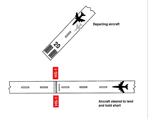
- If, for any reason, such as difficulty in discerning the location of a LAHSO intersection, wind conditions, aircraft condition, etc., the pilot elects to request to land on the full length of the runway, to land on another runway, or to decline LAHSO, a pilot is expected to promptly inform air traffic, ideally even before the clearance is issued. A LAHSO clearance, once accepted, must be adhered to, just as any other ATC clearance, unless an amended clearance is obtained or an emergency occurs. A LAHSO clearance does not preclude a rejected landing.
- A pilot who accepts a LAHSO clearance should land and exit the runway at the first convenient taxiway (unless directed otherwise) before reaching the hold short point. Otherwise, the pilot must stop and hold at the hold short point. If a rejected landing becomes necessary after accepting a LAHSO clearance, the pilot should maintain safe separation from other aircraft or vehicles, and should promptly notify the controller.
- Controllers need a full read back of all LAHSO clearances. Pilots should read back their LAHSO clearance and include the words, “HOLD SHORT OF (RUNWAY/TAXIWAY/OR POINT)” in their acknowledgment of all LAHSO clearances. In order to reduce frequency congestion, pilots are encouraged to read back the LAHSO clearance without prompting. Don't make the controller have to ask for a read back!
-
LAHSO Situational Awareness
- Situational awareness is vital to the success of LAHSO. Situational awareness starts with having current airport information in the cockpit, readily accessible to the pilot. (An airport diagram assists pilots in identifying their location on the airport, thus reducing requests for “progressive taxi instructions” from controllers.)
-
Situational awareness includes effective pilot-controller radio communication. ATC expects pilots to specifically acknowledge and read back all LAHSO clearances as follows:
EXAMPLE-
ATC: “(Aircraft ID) cleared to land runway six right, hold short of taxiway bravo for crossing traffic (type aircraft).”
Aircraft: “(Aircraft ID), wilco, cleared to land runway six right to hold short of taxiway bravo.”
ATC: “(Aircraft ID) cross runway six right at taxiway bravo, landing aircraft will hold short.”
Aircraft: “(Aircraft ID), wilco, cross runway six right at bravo, landing traffic (type aircraft) to hold.” - For those airplanes flown with two crewmembers, effective intra-cockpit communication between cockpit crewmembers is also critical. There have been several instances where the pilot working the radios accepted a LAHSO clearance but then simply forgot to tell the pilot flying the aircraft.
- Situational awareness also includes a thorough understanding of the airport markings, signage, and lighting associated with LAHSO. These visual aids consist of a three-part system of yellow hold-short markings, red and white signage and, in certain cases, in-pavement lighting. Visual aids assist the pilot in determining where to hold short. FIG 4-3-8, FIG 4-3-9, FIG 4-3-10 depict how these markings, signage, and lighting combinations will appear once installed. Pilots are cautioned that not all airports conducting LAHSO have installed any or all of the above markings, signage, or lighting.
- Pilots should only receive a LAHSO clearance when there is a minimum ceiling of 1,000 feet and 3 statute miles visibility. The intent of having “basic” VFR weather conditions is to allow pilots to maintain visual contact with other aircraft and ground vehicle operations. Pilots should consider the effects of prevailing inflight visibility (such as landing into the sun) and how it may affect overall situational awareness. Additionally, surface vehicles and aircraft being taxied by maintenance personnel may also be participating in LAHSO, especially in those operations that involve crossing an active runway.
-
Low Approach
- A low approach (sometimes referred to as a low pass) is the go-around maneuver following an approach. Instead of landing or making a touch-and-go, a pilot may wish to go around (low approach) in order to expedite a particular operation (a series of practice instrument approaches is an example of such an operation). Unless otherwise authorized by ATC, the low approach should be made straight ahead, with no turns or climb made until the pilot has made a thorough visual check for other aircraft in the area.
- When operating within a Class B, Class C, and Class D surface area, a pilot intending to make a low approach should contact the tower for approval. This request should be made prior to starting the final approach.
-
When operating to an airport, not within a Class B, Class C, and Class D surface area, a pilot intending to make a low approach should, prior to leaving the final approach fix inbound (nonprecision approach) or the outer marker or fix used in lieu of the outer marker inbound (precision approach), so advise the FSS, UNICOM, or make a broadcast as appropriate.
REFERENCE-
AIM, Para 4-1-9, Traffic Advisory Practices at Airports Without Operating Control Towers.
-
Traffic Control Light Signals
- The following procedures are used by ATCTs in the control of aircraft, ground vehicles, equipment, and personnel not equipped with radio. These same procedures will be used to control aircraft, ground vehicles, equipment, and personnel equipped with radio if radio contact cannot be established. ATC personnel use a directive traffic control signal which emits an intense narrow light beam of a selected color (either red, white, or green) when controlling traffic by light signals.
-
Although the traffic signal light offers the advantage that some control may be exercised over nonradio equipped aircraft, pilots should be cognizant of the disadvantages which are:
- Pilots may not be looking at the control tower at the time a signal is directed toward their aircraft.
- The directions transmitted by a light signal are very limited since only approval or disapproval of a pilot's anticipated actions may be transmitted. No supplement or explanatory information may be transmitted except by the use of the “General Warning Signal” which advises the pilot to be on the alert.
- Between sunset and sunrise, a pilot wishing to attract the attention of the control tower should turn on a landing light and taxi the aircraft into a position, clear of the active runway, so that light is visible to the tower. The landing light should remain on until appropriate signals are received from the tower.
- Airport Traffic Control Tower Light Gun Signals. (See TBL 4-3-1.)
-
During daylight hours, acknowledge tower transmissions or light signals by moving the ailerons or rudder. At night, acknowledge by blinking the landing or navigation lights. If radio malfunction occurs after departing the parking area, watch the tower for light signals or monitor tower frequency.
TBL 4-3-1
Airport Traffic Control Tower Light Gun SignalsMeaning
Color and Type of Signal
Movement of Vehicles, Equipment and Personnel
Aircraft on the Ground
Aircraft in Flight
Steady green
Cleared to cross, proceed or go
Cleared for takeoff
Cleared to land
Flashing green
Not applicable
Cleared for taxi
Return for landing (to be followed by steady green at the proper time)
Steady red
STOP
STOP
Give way to other aircraft and continue circling
Flashing red
Clear the taxiway/runway
Taxi clear of the runway in use
Airport unsafe, do not land
Flashing white
Return to starting point on airport
Return to starting point on airport
Not applicable
Alternating red and green
Exercise extreme caution
Exercise extreme caution
Exercise extreme caution
-
Communications
-
Pilots of departing aircraft should communicate with the control tower on the appropriate ground control/clearance delivery frequency prior to starting engines to receive engine start time, taxi and/or clearance information. Unless otherwise advised by the tower, remain on that frequency during taxiing and runup, then change to local control frequency when ready to request takeoff clearance.
NOTE-
Pilots are encouraged to monitor the local tower frequency as soon as practical consistent with other ATC requirements.
REFERENCE-
AIM, Para 4-1-13, Automatic Terminal Information Service (ATIS).
- The tower controller will consider that pilots of turbine-powered aircraft are ready for takeoff when they reach the runway or warm-up block unless advised otherwise.
- The majority of ground control frequencies are in the 121.6-121.9 MHz bandwidth. Ground control frequencies are provided to eliminate frequency congestion on the tower (local control) frequency and are limited to communications between the tower and aircraft on the ground and between the tower and utility vehicles on the airport, provide a clear VHF channel for arriving and departing aircraft. They are used for issuance of taxi information, clearances, and other necessary contacts between the tower and aircraft or other vehicles operated on the airport. A pilot who has just landed should not change from the tower frequency to the ground control frequency until directed to do so by the controller. Normally, only one ground control frequency is assigned at an airport; however, at locations where the amount of traffic so warrants, a second ground control frequency and/or another frequency designated as a clearance delivery frequency, may be assigned.
- A controller may omit the ground or local control frequency if the controller believes the pilot knows which frequency is in use. If the ground control frequency is in the 121 MHz bandwidth the controller may omit the numbers preceding the decimal point; e.g., 121.7, “CONTACT GROUND POINT SEVEN.” However, if any doubt exists as to what frequency is in use, the pilot should promptly request the controller to provide that information.
- Controllers will normally avoid issuing a radio frequency change to helicopters, known to be single-piloted, which are hovering, air taxiing, or flying near the ground. At times, it may be necessary for pilots to alert ATC regarding single pilot operations to minimize delay of essential ATC communications. Whenever possible, ATC instructions will be relayed through the frequency being monitored until a frequency change can be accomplished. You must promptly advise ATC if you are unable to comply with a frequency change. Also, you should advise ATC if you must land to accomplish the frequency change unless it is clear the landing will have no impact on other air traffic; e.g., on a taxiway or in a helicopter operating area.
-
Pilots of departing aircraft should communicate with the control tower on the appropriate ground control/clearance delivery frequency prior to starting engines to receive engine start time, taxi and/or clearance information. Unless otherwise advised by the tower, remain on that frequency during taxiing and runup, then change to local control frequency when ready to request takeoff clearance.
-
Gate Holding Due to Departure Delays
- Pilots should contact ground control or clearance delivery prior to starting engines as gate hold procedures will be in effect whenever departure delays exceed or are anticipated to exceed 15 minutes. The sequence for departure will be maintained in accordance with initial call up unless modified by flow control restrictions. Pilots should monitor the ground control or clearance delivery frequency for engine startup advisories or new proposed start time if the delay changes.
- The tower controller will consider that pilots of turbine-powered aircraft are ready for takeoff when they reach the runway or warm-up block unless advised otherwise.
-
VFR Flights in Terminal Areas
Use reasonable restraint in exercising the prerogative of VFR flight, especially in terminal areas. The weather minimums and distances from clouds are minimums. Giving yourself a greater margin in specific instances is just good judgment.
- Approach Area. Conducting a VFR operation in a Class B, Class C, Class D, and Class E surface area when the official visibility is 3 or 4 miles is not prohibited, but good judgment would dictate that you keep out of the approach area.
- Reduced Visibility. It has always been recognized that precipitation reduces forward visibility. Consequently, although again it may be perfectly legal to cancel your IFR flight plan at any time you can proceed VFR, it is good practice, when precipitation is occurring, to continue IFR operation into a terminal area until you are reasonably close to your destination.
- Simulated Instrument Flights. In conducting simulated instrument flights, be sure that the weather is good enough to compensate for the restricted visibility of the safety pilot and your greater concentration on your flight instruments. Give yourself a little greater margin when your flight plan lies in or near a busy airway or close to an airport.
-
VFR Helicopter Operations at Controlled Airports
-
General.
- The following ATC procedures and phraseologies recognize the unique capabilities of helicopters and were developed to improve service to all users. Helicopter design characteristics and user needs often require operations from movement areas and nonmovement areas within the airport boundary. In order for ATC to properly apply these procedures, it is essential that pilots familiarize themselves with the local operations and make it known to controllers when additional instructions are necessary.
- Insofar as possible, helicopter operations will be instructed to avoid the flow of fixed-wing aircraft to minimize overall delays; however, there will be many situations where faster/larger helicopters may be integrated with fixed-wing aircraft for the benefit of all concerned. Examples would include IFR flights, avoidance of noise sensitive areas, or use of runways/taxiways to minimize the hazardous effects of rotor downwash in congested areas.
- Because helicopter pilots are intimately familiar with the effects of rotor downwash, they are best qualified to determine if a given operation can be conducted safely. Accordingly, the pilot has the final authority with respect to the specific airspeed/altitude combinations. ATC clearances are in no way intended to place the helicopter in a hazardous position. It is expected that pilots will advise ATC if a specific clearance will cause undue hazards to persons or property.
-
Controllers normally limit ATC ground service and instruction to movement areas; therefore, operations from nonmovement areas are conducted at pilot discretion and should be based on local policies, procedures, or letters of agreement. In order to maximize the flexibility of helicopter operations, it is necessary to rely heavily on sound pilot judgment. For example, hazards such as debris, obstructions, vehicles, or personnel must be recognized by the pilot, and action should be taken as necessary to avoid such hazards. Taxi, hover taxi, and air taxi operations are considered to be ground movements. Helicopters conducting such operations are expected to adhere to the same conditions, requirements, and practices as apply to other ground taxiing and ATC procedures in the AIM.
- The phraseology taxi is used when it is intended or expected that the helicopter will taxi on the airport surface, either via taxiways or other prescribed routes. Taxi is used primarily for helicopters equipped with wheels or in response to a pilot request. Preference should be given to this procedure whenever it is necessary to minimize effects of rotor downwash.
- Pilots may request a hover taxi when slow forward movement is desired or when it may be appropriate to move very short distances. Pilots should avoid this procedure if rotor downwash is likely to cause damage to parked aircraft or if blowing dust/snow could obscure visibility. If it is necessary to operate above 25 feet AGL when hover taxiing, the pilot should initiate a request to ATC.
-
Air taxi is the preferred method for helicopter ground movements on airports provided ground operations and conditions permit. Unless otherwise requested or instructed, pilots are expected to remain below 100 feet AGL. However, if a higher than normal airspeed or altitude is desired, the request should be made prior to lift-off. The pilot is solely responsible for selecting a safe airspeed for the altitude/operation being conducted. Use of air taxi enables the pilot to proceed at an optimum airspeed/altitude, minimize downwash effect, conserve fuel, and expedite movement from one point to another. Helicopters should avoid overflight of other aircraft, vehicles, and personnel during air-taxi operations. Caution must be exercised concerning active runways and pilots must be certain that air taxi instructions are understood. Special precautions may be necessary at unfamiliar airports or airports with multiple/intersecting active runways. The taxi procedures given in paragraph 4-3-18, Taxiing, paragraph 4-3-19, Taxi During Low Visibility, and paragraph 4-3-21, Exiting the Runway After Landing, also apply.
REFERENCE-
P/CG Term - TAXI.
P/CG Term - HOVER TAXI.
P/CG Term - AIR TAXI.
-
Takeoff and Landing Procedures.
- Helicopter operations may be conducted from a runway, taxiway, portion of a landing strip, or any clear area which could be used as a landing site such as the scene of an accident, a construction site, or the roof of a building. The terms used to describe designated areas from which helicopters operate are: movement area, landing/takeoff area, apron/ramp, heliport and helipad (See Pilot/Controller Glossary). These areas may be improved or unimproved and may be separate from or located on an airport/heliport. ATC will issue takeoff clearances from movement areas other than active runways, or in diverse directions from active runways, with additional instructions as necessary. Whenever possible, takeoff clearance will be issued in lieu of extended hover/air taxi operations. Phraseology will be “CLEARED FOR TAKEOFF FROM (taxiway, helipad, runway number, etc.), MAKE RIGHT/ LEFT TURN FOR (direction, heading, NAVAID radial) DEPARTURE/DEPARTURE ROUTE (number, name, etc.).” Unless requested by the pilot, downwind takeoffs will not be issued if the tailwind exceeds 5 knots.
- Pilots should be alert to wind information as well as to wind indications in the vicinity of the helicopter. ATC should be advised of the intended method of departing. A pilot request to takeoff in a given direction indicates that the pilot is willing to accept the wind condition and controllers will honor the request if traffic permits. Departure points could be a significant distance from the control tower and it may be difficult or impossible for the controller to determine the helicopter's relative position to the wind.
- If takeoff is requested from nonmovement areas, an area not authorized for helicopter use, an area not visible from the tower, an unlighted area at night, or an area off the airport, the phraseology “DEPARTURE FROM (requested location) WILL BE AT YOUR OWN RISK (additional instructions, as necessary). USE CAUTION (if applicable)." The pilot is responsible for operating in a safe manner and should exercise due caution.
- Similar phraseology is used for helicopter landing operations. Every effort will be made to permit helicopters to proceed direct and land as near as possible to their final destination on the airport. Traffic density, the need for detailed taxiing instructions, frequency congestion, or other factors may affect the extent to which service can be expedited. As with ground movement operations, a high degree of pilot/controller cooperation and communication is necessary to achieve safe and efficient operations.
-
General.
-
Taxiing
-
General. Approval must be obtained prior to moving an aircraft or vehicle onto the movement area during the hours an Airport Traffic Control Tower is in operation.
- Always state your position on the airport when calling the tower for taxi instructions.
- The movement area is normally described in local bulletins issued by the airport manager or control tower. These bulletins may be found in FSSs, fixed base operators offices, air carrier offices, and operations offices.
- The control tower also issues bulletins describing areas where they cannot provide ATC service due to nonvisibility or other reasons.
- A clearance must be obtained prior to taxiing on a runway, taking off, or landing during the hours an Airport Traffic Control Tower is in operation.
- A clearance must be obtained prior to crossing any runway. ATC will issue an explicit clearance for all runway crossings.
- When assigned a takeoff runway, ATC will first specify the runway, issue taxi instructions, and state any hold short instructions or runway crossing clearances if the taxi route will cross a runway. This does not authorize the aircraft to “enter” or “cross” the assigned departure runway at any point. In order to preclude misunderstandings in radio communications, ATC will not use the word “cleared” in conjunction with authorization for aircraft to taxi.
-
When issuing taxi instructions to any point other than an assigned takeoff runway, ATC will specify the point to taxi to, issue taxi instructions, and state any hold short instructions or runway crossing clearances if the taxi route will cross a runway.
NOTE-
ATC is required to obtain a readback from the pilot of all runway hold short instructions.
- If a pilot is expected to hold short of a runway approach/departure (Runway XX APPCH/Runway XX DEP) hold area or ILS holding position (see FIG 2-3-15, Taxiways Located in Runway Approach Area), ATC will issue instructions.
-
When taxi instructions are received from the controller, pilots should always read back:
- The runway assignment.
- Any clearance to enter a specific runway.
- Any instruction to hold short of a specific runway or line up and wait.
- Controllers are required to request a readback of runway hold short assignment when it is not received from the pilot/vehicle.
-
ATC clearances or instructions pertaining to taxiing are predicated on known traffic and known physical airport conditions. Therefore, it is important that pilots clearly understand the clearance or instruction. Although an ATC clearance is issued for taxiing purposes, when operating in accordance with the CFRs, it is the responsibility of the pilot to avoid collision with other aircraft. Since “the pilot-in-command of an aircraft is directly responsible for, and is the final authority as to, the operation of that aircraft” the pilot should obtain clarification of any clearance or instruction which is not understood.
-
Good operating practice dictates that pilots acknowledge all runway crossing, hold short, or takeoff clearances unless there is some misunderstanding, at which time the pilot should query the controller until the clearance is understood.
NOTE-
Air traffic controllers are required to obtain from the pilot a readback of all runway hold short instructions.
- Pilots operating a single pilot aircraft should monitor only assigned ATC communications after being cleared onto the active runway for departure. Single pilot aircraft should not monitor other than ATC communications until flight from Class B, Class C, or Class D surface area is completed. This same procedure should be practiced from after receipt of the clearance for landing until the landing and taxi activities are complete. Proper effective scanning for other aircraft, surface vehicles, or other objects should be continuously exercised in all cases.
- If the pilot is unfamiliar with the airport or for any reason confusion exists as to the correct taxi routing, a request may be made for progressive taxi instructions which include step-by-step routing directions. Progressive instructions may also be issued if the controller deems it necessary due to traffic or field conditions (for example, construction or closed taxiways).
-
Good operating practice dictates that pilots acknowledge all runway crossing, hold short, or takeoff clearances unless there is some misunderstanding, at which time the pilot should query the controller until the clearance is understood.
- At those airports where the U.S. Government operates the control tower and ATC has authorized noncompliance with the requirement for two-way radio communications while operating within the Class B, Class C, or Class D surface area, or at those airports where the U.S. Government does not operate the control tower and radio communications cannot be established, pilots must obtain a clearance by visual light signal prior to taxiing on a runway and prior to takeoff and landing.
-
The following phraseologies and procedures are used in radiotelephone communications with aeronautical ground stations.
-
Request for taxi instructions prior to departure.State your aircraft identification, location, type of operation planned (VFR or IFR), and the point of first intended landing.
EXAMPLE-
Aircraft: “Washington ground, Beechcraft One Three One Five Niner at hangar eight, ready to taxi, I-F-R to Chicago.”
Tower: “Beechcraft one three one five niner, Washington ground, runway two seven, taxi via taxiways Charlie and Delta, hold short of runway three three left.”
Aircraft: “Beechcraft One Three One Five Niner, runway two seven, hold short of runway three three left.”
-
Receipt of ATC clearance. ARTCC clearances are relayed to pilots by airport traffic controllers in the following manner.
EXAMPLE-
Tower: “Beechcraft One Three One Five Niner, cleared to the Chicago Midway Airport via Victor Eight, maintain eight thousand.”
Aircraft: “Beechcraft One Three One Five Niner, cleared to the Chicago Midway Airport via Victor Eight, maintain eight thousand.”NOTE-
Normally, an ATC IFR clearance is relayed to a pilot by the ground controller. At busy locations, however, pilots may be instructed by the ground controller to “contact clearance delivery” on a frequency designated for this purpose. No surveillance or control over the movement of traffic is exercised by this position of operation.
-
Request for taxi instructions after landing. State your aircraft identification, location, and that you request taxi instructions.
EXAMPLE-
Aircraft: “Dulles ground, Beechcraft One Four Two Six One clearing runway one right on taxiway echo three, request clearance to Page.”
Tower: “Beechcraft One Four Two Six One, Dulles ground, taxi to Page via taxiways echo three, echo one, and echo niner.”
or
Aircraft: “Orlando ground, Beechcraft One Four Two Six One clearing runway one eight left at taxiway bravo three, request clearance to Page.”
Tower: “Beechcraft One Four Two Six One, Orlando ground, hold short of runway one eight right.”
Aircraft: “Beechcraft One Four Two Six One, hold short of runway one eight right.”
-
Request for taxi instructions prior to departure.State your aircraft identification, location, type of operation planned (VFR or IFR), and the point of first intended landing.
- During ground operations, jet blast, prop wash, and rotor wash can cause damage and upsets if encountered at close range. Pilots should consider the effects of jet blast, prop wash, and rotor wash on aircraft, vehicles, and maintenance equipment during ground operations.
-
General. Approval must be obtained prior to moving an aircraft or vehicle onto the movement area during the hours an Airport Traffic Control Tower is in operation.
-
Taxi During Low Visibility
- Pilots and aircraft operators should be constantly aware that during certain low visibility conditions the movement of aircraft and vehicles on airports may not be visible to the tower controller. This may prevent visual confirmation of an aircraft's adherence to taxi instructions.
- Of vital importance is the need for pilots to notify the controller when difficulties are encountered or at the first indication of becoming disoriented. Pilots should proceed with extreme caution when taxiing toward the sun. When vision difficulties are encountered pilots should immediately inform the controller.
-
Advisory Circular 120-57, Low Visibility Operations Surface Movement Guidance and Control System, commonly known as LVOSMGCS (pronounced “LVO SMIGS”) describes an adequate example of a low visibility taxi plan for any airport which has takeoff or landing operations in less than 1,200 feet runway visual range (RVR) visibility conditions. These plans, which affect aircrew and vehicle operators, may incorporate additional lighting, markings, and procedures to control airport surface traffic. They will be addressed at two levels; operations less than 1,200 feet RVR to 500 feet RVR and operations less than 500 feet RVR.
NOTE-
Specific lighting systems and surface markings may be found in paragraph 2-1-10, Taxiway Lights, and paragraph 2-3-4, Taxiway Markings.
- When low visibility conditions exist, pilots should focus their entire attention on the safe operation of the aircraft while it is moving. Checklists and nonessential communication should be withheld until the aircraft is stopped and the brakes set.
-
Standard Taxi Routes
- Standard Taxi Routes (STRs) provide a standard, predictable taxi route from an origination point to a termination point on the airport movement area. The use of STRs helps reduce frequency congestion and streamline taxi procedures. STRs may be available at certain airports. Absent an STR Letter of Agreement (LOA), issuance of an STR will be at the request of the pilot and discretion of ATC. STRs used under an LOA are issued by ATC and are not required to be requested by the pilot.
- STRs are available via two methods, (LOA) or publicly-available via the Domestic Notices website: https://www.faa.gov/air_traffic/publications/domesticnotices/.
- An LOA for STRs will be revised for updates and changes, including cancellation on an as-needed basis with the operator. It is the responsibility of the operator to distribute changes to their flight crews.
- An STR may be requested by a pilot or assigned at the discretion of ATC to the pilot of an operator with an LOA STR. It is the responsibility of the pilot to request a full taxi clearance if not fully familiar with the STR.
- A Letter to Airmen (LTA) will be issued by airport traffic control towers to announce availability, updates, cancelation, or changes of publicly-available STRs with appropriate updates to the Domestic Notices website. An LTA may include an airport diagram. The airport diagram will be labeled “not for navigation” and is not an acceptable substitute for the most up-to-date airport diagrams. LTAs are available via the FAA NOTAM Search website: https://notams.aim.faa.gov/notamSearch/.
- Pilots request publicly-available STRs by stating the desired STR name (e.g., ATC facility, flight or aircraft identification, location, request STR name). By requesting an STR, a pilot acknowledges full familiarity with the STR. The issuance of a pilot-requested STR is at the discretion of ATC.
-
STRs contain the same characteristics and responsibilities:
- Pilots should not request, and ATC may not issue STR instructions during low visibility Surface Movement Guidance and Control System (SMGCS) operations.
- It is the pilot's responsibility to maintain familiarity and awareness of the most current versions of STRs, as well as airport diagrams and charts prior to accepting an STR assignment.
- If a pilot is unsure about the assigned STR procedure, the pilot is encouraged to either seek clarification from ATC or decline the STR assignment.
- Pilots who become disoriented during taxi should advise ATC immediately and request detailed taxi instructions or other assistance.
- An STR instruction does not constitute nor imply a clearance to cross a runway.
- Unless otherwise stated by ATC, the issuance of an STR does not give an aircraft the right of way over another taxiing aircraft.
- Unless otherwise instructed by ATC, originating from, and terminating to a non-movement area as part of an STR is at the discretion of the pilot in coordination with ramp control, if required.
- If ATC instructs the pilot to deviate from an STR, ATC must issue detailed taxi instructions for the remainder of the taxi.
- Pilots are urged to exercise caution when accepting STR assignments, especially when STRs are used or available at more than one airport in the same terminal area.
- ATC may cancel, amend, or revise an STR as necessary. Any updates to publicly-available STRs will be communicated via LTA with appropriate updates to the Domestic Notices website.
-
Exiting the Runway After Landing
The following procedures must be followed after landing and reaching taxi speed.
- Exit the runway without delay at the first available taxiway or on a taxiway as instructed by ATC. Pilots must not exit the landing runway onto another runway unless authorized by ATC. At airports with an operating control tower, pilots should not stop or reverse course on the runway without first obtaining ATC approval.
-
Taxi clear of the runway unless otherwise directed by ATC. An aircraft is considered clear of the runway when all parts of the aircraft are past the runway edge and there are no restrictions to its continued movement beyond the runway holding position markings. In the absence of ATC instructions, the pilot is expected to taxi clear of the landing runway by taxiing beyond the runway holding position markings associated with the landing runway, even if that requires the aircraft to protrude into or cross another taxiway or ramp area. Once all parts of the aircraft have crossed the runway holding position markings, the pilot must hold unless further instructions have been issued by ATC.
NOTE-
-
Immediately change to ground control frequency when advised by the tower and obtain a taxi clearance.
NOTE-
- The tower will issue instructions required to resolve any potential conflictions with other ground traffic prior to advising the pilot to contact ground control.
- Ground control will issue taxi clearance to parking. That clearance does not authorize the aircraft to “enter” or “cross” any runways. Pilots not familiar with the taxi route should request specific taxi instructions from ATC.
-
Practice Instrument Approaches
- Various air traffic incidents have indicated the necessity for adoption of measures to achieve more organized and controlled operations where practice instrument approaches are conducted. Practice instrument approaches are considered to be instrument approaches made by either a VFR aircraft not on an IFR flight plan or an aircraft on an IFR flight plan. To achieve this and thereby enhance air safety, it is Air Traffic's policy to provide for separation of such operations at locations where approach control facilities are located and, as resources permit, at certain other locations served by ARTCCs or parent approach control facilities. Pilot requests to practice instrument approaches may be approved by ATC subject to traffic and workload conditions. Pilots should anticipate that in some instances the controller may find it necessary to deny approval or withdraw previous approval when traffic conditions warrant. It must be clearly understood, however, that even though the controller may be providing separation, pilots on VFR flight plans are required to comply with basic VFR weather minimums (14 CFR section 91.155). Application of ATC procedures or any action taken by the controller to avoid traffic conflictions does not relieve IFR and VFR pilots of their responsibility to see-and-avoid other traffic while operating in VFR conditions (14 CFR section 91.113). In addition to the normal IFR separation minimums (which includes visual separation) during VFR conditions, 500 feet vertical separation may be applied between VFR aircraft and between a VFR aircraft and the IFR aircraft. Pilots not on IFR flight plans desiring practice instrument approaches should always state `practice' when making requests to ATC. Controllers will instruct VFR aircraft requesting an instrument approach to maintain VFR. This is to preclude misunderstandings between the pilot and controller as to the status of the aircraft. If pilots wish to proceed in accordance with instrument flight rules, they must specifically request and obtain, an IFR clearance.
-
Before practicing an instrument approach, pilots should inform the approach control facility or the tower of the type of practice approach they desire to make and how they intend to terminate it, i.e., full-stop landing, touch-and-go, or missed or low approach maneuver. This information may be furnished progressively when conducting a series of approaches. Pilots on an IFR flight plan, who have made a series of instrument approaches to full stop landings should inform ATC when they make their final landing. The controller will control flights practicing instrument approaches so as to ensure that they do not disrupt the flow of arriving and departing itinerant IFR or VFR aircraft. The priority afforded itinerant aircraft over practice instrument approaches is not intended to be so rigidly applied that it causes grossly inefficient application of services. A minimum delay to itinerant traffic may be appropriate to allow an aircraft practicing an approach to complete that approach.
NOTE-
A clearance to land means that appropriate separation on the landing runway will be ensured. A landing clearance does not relieve the pilot from compliance with any previously issued restriction.
- At airports without a tower, pilots wishing to make practice instrument approaches should notify the facility having control jurisdiction of the desired approach as indicated on the approach chart. All approach control facilities and ARTCCs are required to publish a Letter to Airmen depicting those airports where they provide standard separation to both VFR and IFR aircraft conducting practice instrument approaches.
- The controller will provide approved separation between both VFR and IFR aircraft when authorization is granted to make practice approaches to airports where an approach control facility is located and to certain other airports served by approach control or an ARTCC. Controller responsibility for separation of VFR aircraft begins at the point where the approach clearance becomes effective, or when the aircraft enters Class B or Class C airspace, or a TRSA, whichever comes first.
- VFR aircraft practicing instrument approaches are not automatically authorized to execute the missed approach procedure. This authorization must be specifically requested by the pilot and approved by the controller. Where ATC procedures require application of IFR separation to VFR aircraft practicing instrument approaches, separation will be provided throughout the procedure including the missed approach. Where no separation services are provided during the practice approach, no separation services will be provided during the missed approach.
- Except in an emergency, aircraft cleared to practice instrument approaches must not deviate from the approved procedure until cleared to do so by the controller.
- At radar approach control locations when a full approach procedure (procedure turn, etc.,) cannot be approved, pilots should expect to be vectored to a final approach course for a practice instrument approach which is compatible with the general direction of traffic at that airport.
- When granting approval for a practice instrument approach, the controller will usually ask the pilot to report to the tower prior to or over the final approach fix inbound (nonprecision approaches) or over the outer marker or fix used in lieu of the outer marker inbound (precision approaches).
- When authorization is granted to conduct practice instrument approaches to an airport with a tower, but where approved standard separation is not provided to aircraft conducting practice instrument approaches, the tower will approve the practice approach, instruct the aircraft to maintain VFR and issue traffic information, as required.
- When an aircraft notifies a FSS providing Local Airport Advisory to the airport concerned of the intent to conduct a practice instrument approach and whether or not separation is to be provided, the pilot will be instructed to contact the appropriate facility on a specified frequency prior to initiating the approach. At airports where separation is not provided, the FSS will acknowledge the message and issue known traffic information but will neither approve or disapprove the approach.
- Pilots conducting practice instrument approaches should be particularly alert for other aircraft operating in the local traffic pattern or in proximity to the airport.
-
Option Approach
The “Cleared for the Option” procedure will permit an instructor, flight examiner or pilot the option to make a touch-and-go, low approach, missed approach, stop-and-go, or full stop landing. This procedure can be very beneficial in a training situation in that neither the student pilot nor examinee would know what maneuver would be accomplished. The pilot should make a request for this procedure passing the final approach fix inbound on an instrument approach or entering downwind for a VFR traffic pattern. After ATC approval of the option, the pilot should inform ATC as soon as possible of any delay on the runway during their stop-and-go or full stop landing. The advantages of this procedure as a training aid are that it enables an instructor or examiner to obtain the reaction of a trainee or examinee under changing conditions, the pilot would not have to discontinue an approach in the middle of the procedure due to student error or pilot proficiency requirements, and finally it allows more flexibility and economy in training programs. This procedure will only be used at those locations with an operational control tower and will be subject to ATC approval.
-
Use of Aircraft Lights
- Aircraft position lights are required to be lighted on aircraft operated on the surface and in flight from sunset to sunrise. In addition, aircraft equipped with an anti-collision light system are required to operate that light system during all types of operations (day and night). However, during any adverse meteorological conditions, the pilot-in-command may determine that the anti-collision lights should be turned off when their light output would constitute a hazard to safety (14 CFR section 91.209). Supplementary strobe lights should be turned off on the ground when they adversely affect ground personnel or other pilots, and in flight when there are adverse reflection from clouds.
- An aircraft anti-collision light system can use one or more rotating beacons and/or strobe lights, be colored either red or white, and have different (higher than minimum) intensities when compared to other aircraft. Many aircraft have both a rotating beacon and a strobe light system.
- The FAA has a voluntary pilot safety program, Operation Lights On, to enhance the see-and-avoid concept. Pilots are encouraged to turn on their landing lights during takeoff; i.e., either after takeoff clearance has been received or when beginning takeoff roll. Pilots are further encouraged to turn on their landing lights when operating below 10,000 feet, day or night, especially when operating within 10 miles of any airport, or in conditions of reduced visibility and in areas where flocks of birds may be expected, i.e., coastal areas, lake areas, around refuse dumps, etc. Although turning on aircraft lights does enhance the see-and-avoid concept, pilots should not become complacent about keeping a sharp lookout for other aircraft. Not all aircraft are equipped with lights and some pilots may not have their lights turned on. Aircraft manufacturer's recommendations for operation of landing lights and electrical systems should be observed.
- Prop and jet blast forces generated by large aircraft have overturned or damaged several smaller aircraft taxiing behind them. To avoid similar results, and in the interest of preventing upsets and injuries to ground personnel from such forces, the FAA recommends that air carriers and commercial operators turn on their rotating beacons anytime their aircraft engines are in operation. General aviation pilots using rotating beacon equipped aircraft are also encouraged to participate in this program which is designed to alert others to the potential hazard. Since this is a voluntary program, exercise caution and do not rely solely on the rotating beacon as an indication that aircraft engines are in operation.
- Prior to commencing taxi, it is recommended to turn on navigation, position, anti-collision, and logo lights (if equipped). To signal intent to other pilots, consider turning on the taxi light when the aircraft is moving or intending to move on the ground, and turning it off when stopped or yielding to other ground traffic. Strobe lights should not be illuminated during taxi if they will adversely affect the vision of other pilots or ground personnel.
- At the discretion of the pilot-in-command, all exterior lights should be illuminated when taxiing on or across any runway. This increases the conspicuousness of the aircraft to controllers and other pilots approaching to land, taxiing, or crossing the runway. Pilots should comply with any equipment operating limitations and consider the effects of landing and strobe lights on other aircraft in their vicinity.
- When entering the departure runway for takeoff or to “line up and wait,” all lights, except for landing lights, should be illuminated to make the aircraft conspicuous to ATC and other aircraft on approach. Landing lights should be turned on when takeoff clearance is received or when commencing takeoff roll at an airport without an operating control tower.
-
Flight Inspection/`Flight Check' Aircraft in Terminal Areas
- Flight check is a call sign used to alert pilots and air traffic controllers when a FAA aircraft is engaged in flight inspection/certification of NAVAIDs and flight procedures. Flight check aircraft fly preplanned high/low altitude flight patterns such as grids, orbits, DME arcs, and tracks, including low passes along the full length of the runway to verify NAVAID performance.
- Pilots should be especially watchful and avoid the flight paths of any aircraft using the call sign “Flight Check.” These flights will normally receive special handling from ATC. Pilot patience and cooperation in allowing uninterrupted recordings can significantly help expedite flight inspections, minimize costly, repetitive runs, and reduce the burden on the U.S. taxpayer.
-
Hand Signals
FIG 4-3-11
Signalman Directs Towing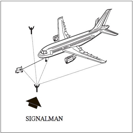
FIG 4-3-12
Signalman's Position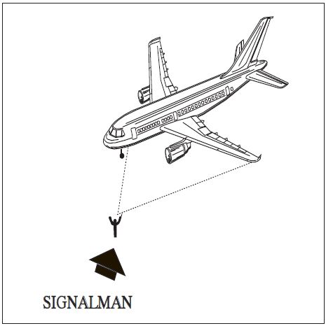
FIG 4-3-13
All Clear (O.K.)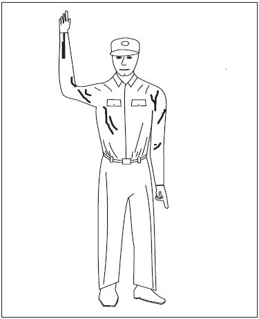
FIG 4-3-14
Start Engine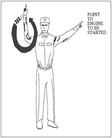
FIG 4-3-15
Pull Chocks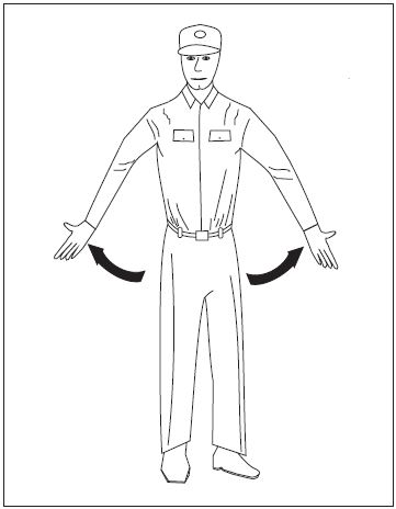
FIG 4-3-16
Proceed Straight Ahead
FIG 4-3-17
Left Turn
FIG 4-3-18
Right Turn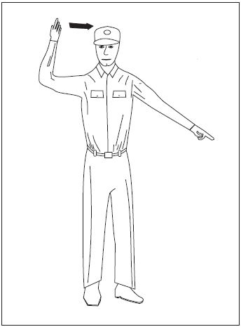
FIG 4-3-19
Slow Down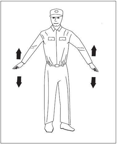
FIG 4-3-20
Flagman Directs Pilot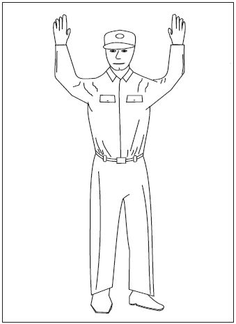
FIG 4-3-21
Insert Chocks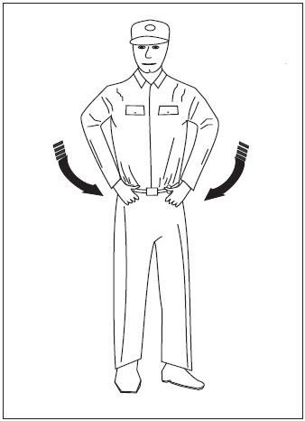
FIG 4-3-22
Cut Engines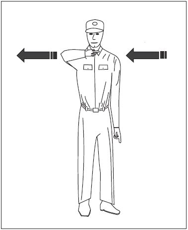
FIG 4-3-23
Night Operation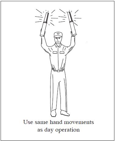
FIG 4-3-24
Stop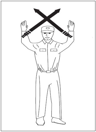
-
Operations at Uncontrolled Airports With Automated Surface Observing System (ASOS)/Automated Weather Observing System (AWOS)
- Many airports throughout the National Airspace System are equipped with either ASOS or AWOS. At most airports with an operating control tower or human observer, the weather will be available to you in an Aviation Routine Weather Report (METAR) hourly or special observation format on the Automatic Terminal Information Service (ATIS) or directly transmitted from the controller/observer.
- At uncontrolled airports that are equipped with ASOS/AWOS with ground-to-air broadcast capability, the one-minute updated airport weather should be available to you within approximately 25 NM of the airport below 10,000 feet. The frequency for the weather broadcast will be published on sectional charts and in the Chart Supplement. Some part-time towered airports may also broadcast the automated weather on their ATIS frequency during the hours that the tower is closed.
-
Controllers issue SVFR or IFR clearances based on pilot request, known traffic and reported weather, i.e., METAR/Nonroutine (Special) Aviation Weather Report (SPECI) observations, when they are available. Pilots have access to more current weather at uncontrolled ASOS/AWOS airports than do the controllers who may be located several miles away. Controllers will rely on the pilot to determine the current airport weather from the ASOS/AWOS. All aircraft arriving or departing an ASOS/AWOS equipped uncontrolled airport should monitor the airport weather frequency to ascertain the status of the airspace. Pilots in Class E airspace must be alert for changing weather conditions which may affect the status of the airspace from IFR/VFR. If ATC service is required for IFR/SVFR approach/departure or requested for VFR service, the pilot should advise the controller that he/she has received the one-minute weather and state his/her intentions.
EXAMPLE-
“I have the (airport) one-minute weather, request an ILS Runway 14 approach.”
REFERENCE-
AIM, Para 7-1-10, Weather Observing Programs.