You have 0 items in your cart

FAR/AIM
>
Aeronautical Information Manual
>
Chapter 4. Air Traffic Control
>
Section 5. Surveillance Systems
Section 5. Surveillance Systems
-
Radar
-
Capabilities
- Radar is a method whereby radio waves are transmitted into the air and are then received when they have been reflected by an object in the path of the beam. Range is determined by measuring the time it takes (at the speed of light) for the radio wave to go out to the object and then return to the receiving antenna. The direction of a detected object from a radar site is determined by the position of the rotating antenna when the reflected portion of the radio wave is received.
- More reliable maintenance and improved equipment have reduced radar system failures to a negligible factor. Most facilities actually have some components duplicated, one operating and another which immediately takes over when a malfunction occurs to the primary component.
-
Limitations
-
It is very important for the aviation community to recognize the fact that there are limitations to radar service and that ATC controllers may not always be able to issue traffic advisories concerning aircraft which are not under ATC control and cannot be seen on radar. (See FIG 4-5-1.)
FIG 4-5-1
Limitations to Radar Service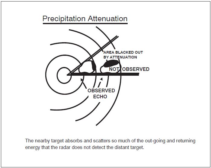
-
The characteristics of radio waves are such that they normally travel in a continuous straight line unless they are:
- “Bent” by abnormal atmospheric phenomena such as temperature inversions;
- Reflected or attenuated by dense objects such as heavy clouds, precipitation, ground obstacles, mountains, etc.; or
- Screened by high terrain features.
- The bending of radar pulses, often called anomalous propagation or ducting, may cause many extraneous blips to appear on the radar operator's display if the beam has been bent toward the ground or may decrease the detection range if the wave is bent upward. It is difficult to solve the effects of anomalous propagation, but using beacon radar and electronically eliminating stationary and slow moving targets by a method called moving target indicator (MTI) usually negate the problem.
- Radar energy that strikes dense objects will be reflected and displayed on the operator's scope thereby blocking out aircraft at the same range and greatly weakening or completely eliminating the display of targets at a greater range. Again, radar beacon and MTI are very effectively used to combat ground clutter and weather phenomena, and a method of circularly polarizing the radar beam will eliminate some weather returns. A negative characteristic of MTI is that an aircraft flying a speed that coincides with the canceling signal of the MTI (tangential or “blind” speed) may not be displayed to the radar controller.
- Relatively low altitude aircraft will not be seen if they are screened by mountains or are below the radar beam due to earth curvature. The historical solution to screening has been the installation of strategically placed multiple radars, which has been done in some areas, but ADS-B now provides ATC surveillance in some areas with challenging terrain where multiple radar installations would be impractical.
- There are several other factors which affect radar control. The amount of reflective surface of an aircraft will determine the size of the radar return. Therefore, a small light airplane or a sleek jet fighter will be more difficult to see on primary radar than a large commercial jet or military bomber. Here again, the use of transponder or ADS-B equipment is invaluable. In addition, all FAA ATC facilities display automatically reported altitude information to the controller from appropriately equipped aircraft.
-
At some locations within the ATC en route environment, secondary-radar-only (no primary radar) gap filler radar systems are used to give lower altitude radar coverage between two larger radar systems, each of which provides both primary and secondary radar coverage. ADS-B serves this same role, supplementing both primary and secondary radar. In those geographical areas served by secondary radar only or ADS-B, aircraft without either transponders or ADS-B equipment cannot be provided with radar service. Additionally, transponder or ADS-B equipped aircraft cannot be provided with radar advisories concerning primary targets and ATC radar-derived weather.
REFERENCE-
P/CG Term - RADAR.
-
With regard to air traffic radar reception, wind turbines generally do not affect the quality of air traffic surveillance radar returns for transponder and ADS-B Out equipped aircraft. Air traffic interference issues apply to the search radar and Non-Transponder/Non-ADS-B Out equipped aircraft.
NOTE-
Generally, one or two wind turbines don't present a significant radar reception loss. A rule of thumb is three (3) or more turbines constitute a wind turbine farm and thus negatively affect the search radar product.
-
Detection loss in the area of a wind turbine farm is substantial. In extreme circumstances, this can extend for more than 1.0 nautical mile (NM) horizontally around the nearest turbine and at all altitudes above the wind turbine farm. (See FIG 4-5-2.)
FIG 4-5-2
Wind Turbine Farm Area of Potential Interference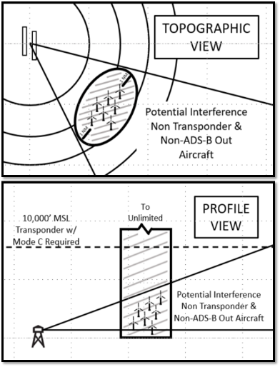
NOTE-
All aircraft should comply with 14 CFR §91.119(c) “…aircraft may not be operated closer than 500 feet to any person, vessel, vehicle, or structure.”
- To avoid interference Non-Transponder/Non-ADS-B Out equipped aircraft should avoid flight within 1.0 NM horizontally, at all altitudes, from the wind turbine farms.
- Because detection loss near and above wind turbine farms for search-only targets causes dropped tracks, erroneous tracks, and can result in loss of separation, it is imperative that Non-Transponder/Non-ADS-B Out equipped aircraft operate at the proper VFR altitudes per hemispheric rule and utilize see-and-avoid techniques.
- Pilots should be aware that air traffic controllers cannot provide separation from Non-Transponder/Non-ADS-B Out equipped aircraft in the vicinity of wind turbine farms. See-and-avoid is the pilot's responsibility, as these non-equipped aircraft may not appear on radar and will not appear on the Traffic Information Services-Broadcast (TIS-B).
-
Detection loss in the area of a wind turbine farm is substantial. In extreme circumstances, this can extend for more than 1.0 nautical mile (NM) horizontally around the nearest turbine and at all altitudes above the wind turbine farm. (See FIG 4-5-2.)
- The controller's ability to advise a pilot flying on instruments or in visual conditions of the aircraft's proximity to another aircraft will be limited if the unknown aircraft is not observed on radar, if no flight plan information is available, or if the volume of traffic and workload prevent issuing traffic information. The controller's first priority is given to establishing vertical, lateral, or longitudinal separation between aircraft flying IFR under the control of ATC.
-
The characteristics of radio waves are such that they normally travel in a continuous straight line unless they are:
-
It is very important for the aviation community to recognize the fact that there are limitations to radar service and that ATC controllers may not always be able to issue traffic advisories concerning aircraft which are not under ATC control and cannot be seen on radar. (See FIG 4-5-1.)
- FAA radar units operate continuously at the locations shown in the Chart Supplement, and their services are available to all pilots, both civil and military. Contact the associated FAA control tower or ARTCC on any frequency guarded for initial instructions, or in an emergency, any FAA facility for information on the nearest radar service.
-
Capabilities
-
Air Traffic Control Radar Beacon System (ATCRBS)
-
The ATCRBS, sometimes referred to as secondary surveillance radar, consists of three main components:
- Interrogator. Primary radar relies on a signal being transmitted from the radar antenna site and for this signal to be reflected or “bounced back” from an object (such as an aircraft). This reflected signal is then displayed as a “target” on the controller's radarscope. In the ATCRBS, the Interrogator, a ground based radar beacon transmitter-receiver, scans in synchronism with the primary radar and transmits discrete radio signals which repetitiously request all transponders, on the mode being used, to reply. The replies received are then mixed with the primary returns and both are displayed on the same radarscope.
- Transponder. This airborne radar beacon transmitter-receiver automatically receives the signals from the interrogator and selectively replies with a specific pulse group (code) only to those interrogations being received on the mode to which it is set. These replies are independent of, and much stronger than a primary radar return.
- Radarscope. The radarscope used by the controller displays returns from both the primary radar system and the ATCRBS. These returns, called targets, are what the controller refers to in the control and separation of traffic.
-
The job of identifying and maintaining identification of primary radar targets is a long and tedious task for the controller. Some of the advantages of ATCRBS over primary radar are:
- Reinforcement of radar targets.
- Rapid target identification.
- Unique display of selected codes.
- A part of the ATCRBS ground equipment is the decoder. This equipment enables a controller to assign discrete transponder codes to each aircraft under his/her control. Normally only one code will be assigned for the entire flight. Assignments are made by the ARTCC computer on the basis of the National Beacon Code Allocation Plan. The equipment is also designed to receive Mode C altitude information from the aircraft.
-
It should be emphasized that aircraft transponders greatly improve the effectiveness of radar systems.
REFERENCE-
AIM, Para 4-1-20, Transponder and ADS-B Out Operation.
-
The ATCRBS, sometimes referred to as secondary surveillance radar, consists of three main components:
-
Surveillance Radar
-
Surveillance radars are divided into two general categories: Airport Surveillance Radar (ASR) and Air Route Surveillance Radar (ARSR).
- ASR is designed to provide relatively short-range coverage in the general vicinity of an airport and to serve as an expeditious means of handling terminal area traffic through observation of precise aircraft locations on a radarscope. The ASR can also be used as an instrument approach aid.
- ARSR is a long-range radar system designed primarily to provide a display of aircraft locations over large areas.
- Surveillance radars scan through 360 degrees of azimuth and present target information on a radar display located in a tower or center. This information is used independently or in conjunction with other navigational aids in the control of air traffic.
-
Surveillance radars are divided into two general categories: Airport Surveillance Radar (ASR) and Air Route Surveillance Radar (ARSR).
-
Precision Approach Radar (PAR)
- PAR is designed for use as a landing aid rather than an aid for sequencing and spacing aircraft. PAR equipment may be used as a primary landing aid (See Chapter 5, Air Traffic Procedures, for additional information), or it may be used to monitor other types of approaches. It is designed to display range, azimuth, and elevation information.
- Two antennas are used in the PAR array, one scanning a vertical plane, and the other scanning horizontally. Since the range is limited to 10 miles, azimuth to 20 degrees, and elevation to 7 degrees, only the final approach area is covered. Each scope is divided into two parts. The upper half presents altitude and distance information, and the lower half presents azimuth and distance.
-
Airport Surface Detection Equipment (ASDE-X)/Airport Surface Surveillance Capability (ASSC)
-
ASDE-X/ASSC is a multi-sensor surface surveillance system the FAA has acquired for airports in the United States. This system provides high resolution, short-range, clutter free surveillance information about aircraft and vehicles, both moving and fixed, located on or near the surface of the airport's runways and taxiways under all weather and visibility conditions. The system consists of:
- A Primary Radar System. ASDE-X/ASSC system coverage includes the airport surface and the airspace up to 200 feet above the surface. Typically located on the control tower or other strategic location on the airport, the Primary Radar antenna is able to detect and display aircraft that are not equipped with or have malfunctioning transponders or ADS-B.
- Interfaces. ASDE-X/ASSC contains an automation interface for flight identification via all automation platforms and interfaces with the terminal radar for position information.
- Automation. A Multi-sensor Data Processor (MSDP) combines all sensor reports into a single target which is displayed to the air traffic controller.
- Air Traffic Control Tower Display. A high resolution, color monitor in the control tower cab provides controllers with a seamless picture of airport operations on the airport surface.
- The combination of data collected from the multiple sensors ensures that the most accurate information about aircraft location is received in the tower, thereby increasing surface safety and efficiency.
-
The following facilities are operational with ASDE-X:
TBL 4-5-1
BWI
Baltimore Washington International
BOS
Boston Logan International
BDL
Bradley International
MDW
Chicago Midway
ORD
Chicago O'Hare International
CLT
Charlotte Douglas International
DFW
Dallas/Fort Worth International
DEN
Denver International
DTW
Detroit Metro Wayne County
FLL
Fort Lauderdale/Hollywood Intl
MKE
General Mitchell International
IAH
George Bush International
ATL
Hartsfield-Jackson Atlanta Intl
HNL
Honolulu International
JFK
John F. Kennedy International
SNA
John Wayne-Orange County
LGA
LaGuardia
STL
Lambert St. Louis International
LAS
Las Vegas Harry Reid International
LAX
Los Angeles International
SDF
Louisville International
MEM
Memphis International
MIA
Miami International
MSP
Minneapolis St. Paul International
EWR
Newark International
MCO
Orlando International
PHL
Philadelphia International
PHX
Phoenix Sky Harbor International
DCA
Ronald Reagan Washington National
SAN
San Diego International
SLC
Salt Lake City International
SEA
Seattle-Tacoma International
PVD
Theodore Francis Green State
IAD
Washington Dulles International
HOU
William P. Hobby International
-
The following facilities have been projected to receive ASSC:
TBL 4-5-2
SFO
San Francisco International
CLE
Cleveland-Hopkins International
MCI
Kansas City International
CVG
Cincinnati/Northern Kentucky Intl
PDX
Portland International
MSY
Louis Armstrong New Orleans Intl
PIT
Pittsburgh International
ANC
Ted Stevens Anchorage International
ADW
Joint Base Andrews AFB
-
ASDE-X/ASSC is a multi-sensor surface surveillance system the FAA has acquired for airports in the United States. This system provides high resolution, short-range, clutter free surveillance information about aircraft and vehicles, both moving and fixed, located on or near the surface of the airport's runways and taxiways under all weather and visibility conditions. The system consists of:
-
Traffic Information Service (TIS)
- Introduction. The Traffic Information Service (TIS) provides information to the cockpit via data link, that is similar to VFR radar traffic advisories normally received over voice radio. Among the first FAA-provided data services, TIS is intended to improve the safety and efficiency of “see and avoid” flight through an automatic display that informs the pilot of nearby traffic and potential conflict situations. This traffic display is intended to assist the pilot in visual acquisition of these aircraft. TIS employs an enhanced capability of the terminal Mode S radar system, which contains the surveillance data, as well as the data link required to “uplink” this information to suitably-equipped aircraft (known as a TIS “client”). TIS provides estimated position, altitude, altitude trend, and ground track information for up to 8 intruder aircraft within 7 NM horizontally, +3,500 and -3,000 feet vertically of the client aircraft (see FIG 4-5-3, TIS Proximity Coverage Volume). The range of a target reported at a distance greater than 7 NM only indicates that this target will be a threat within 34 seconds and does not display a precise distance. TIS will alert the pilot to aircraft (under surveillance of the Mode S radar) that are estimated to be within 34 seconds of potential collision, regardless of distance or altitude. TIS surveillance data is derived from the same radar used by ATC; this data is uplinked to the client aircraft on each radar scan (nominally every 5 seconds).
-
Requirements.
-
In order to use TIS, the client and any intruder aircraft must be equipped with the appropriate cockpit equipment and fly within the radar coverage of a Mode S radar capable of providing TIS. Typically, this will be within 55 NM of the sites depicted in FIG 4-5-4, Terminal Mode S Radar Sites. ATC communication is not a requirement to receive TIS, although it may be required by the particular airspace or flight operations in which TIS is being used.
FIG 4-5-3
TIS Proximity Coverage Volume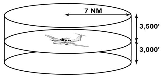
FIG 4-5-4
Terminal Mode S Radar Sites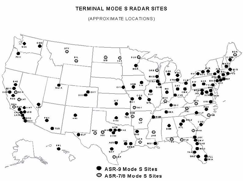
FIG 4-5-5
Traffic Information Service (TIS) Avionics Block Diagram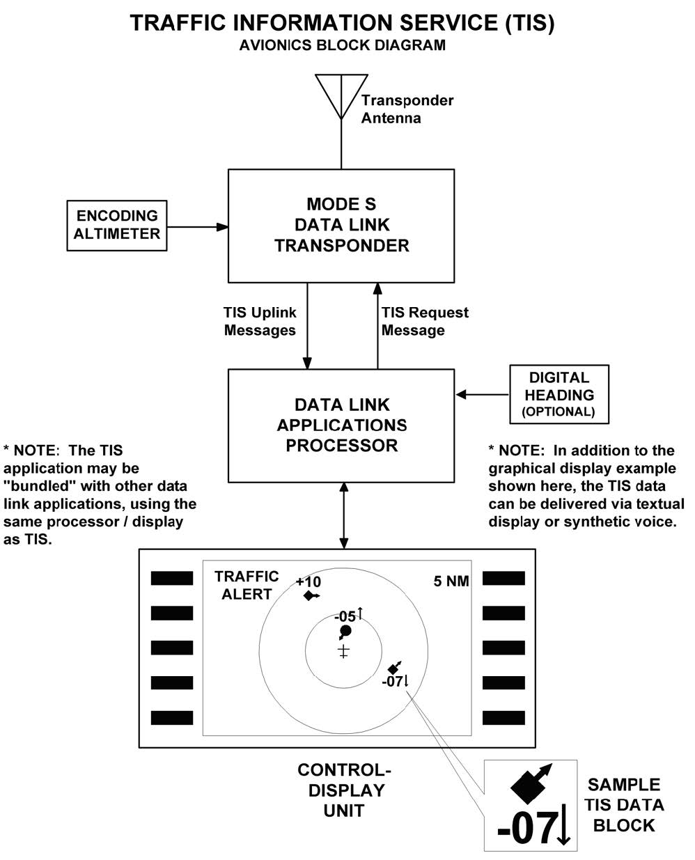
-
The cockpit equipment functionality required by a TIS client aircraft to receive the service consists of the following (refer to FIG 4-5-5):
- Mode S data link transponder with altitude encoder.
- Data link applications processor with TIS software installed.
- Control-display unit.
-
Optional equipment includes a digital heading source to correct display errors caused by “crab angle” and turning maneuvers.
NOTE-
Some of the above functions will likely be combined into single pieces of avionics, such as (a) and (b).
- To be visible to the TIS client, the intruder aircraft must, at a minimum, have an operating transponder (Mode A, C or S). All altitude information provided by TIS from intruder aircraft is derived from Mode C reports, if appropriately equipped.
-
TIS will initially be provided by the terminal Mode S systems that are paired with ASR-9 digital primary radars. These systems are in locations with the greatest traffic densities, thus will provide the greatest initial benefit. The remaining terminal Mode S sensors, which are paired with ASR-7 or ASR-8 analog primary radars, will provide TIS pending modification or relocation of these sites. See FIG 4-5-4, Terminal Mode S Radar Sites, for site locations. There is no mechanism in place, such as NOTAMs, to provide status update on individual radar sites since TIS is a nonessential, supplemental information service.
The FAA also operates en route Mode S radars (not illustrated) that rotate once every 12 seconds. These sites will require additional development of TIS before any possible implementation. There are no plans to implement TIS in the en route Mode S radars at the present time.
-
In order to use TIS, the client and any intruder aircraft must be equipped with the appropriate cockpit equipment and fly within the radar coverage of a Mode S radar capable of providing TIS. Typically, this will be within 55 NM of the sites depicted in FIG 4-5-4, Terminal Mode S Radar Sites. ATC communication is not a requirement to receive TIS, although it may be required by the particular airspace or flight operations in which TIS is being used.
-
Capabilities.
- TIS provides ground-based surveillance information over the Mode S data link to properly equipped client aircraft to aid in visual acquisition of proximate air traffic. The actual avionics capability of each installation will vary and the supplemental handbook material must be consulted prior to using TIS. A maximum of eight (8) intruder aircraft may be displayed; if more than eight aircraft match intruder parameters, the eight “most significant” intruders are uplinked. These “most significant” intruders are usually the ones in closest proximity and/or the greatest threat to the TIS client.
-
TIS, through the Mode S ground sensor, provides the following data on each intruder aircraft:
- Relative bearing information in 6-degree increments.
- Relative range information in 1/8 NM to 1 NM increments (depending on range).
- Relative altitude in 100-foot increments (within 1,000 feet) or 500-foot increments (from 1,000-3,500 feet) if the intruder aircraft has operating altitude reporting capability.
- Estimated intruder ground track in 45-degree increments.
- Altitude trend data (level within 500 fpm or climbing/descending >500 fpm) if the intruder aircraft has operating altitude reporting capability.
- Intruder priority as either an “traffic advisory” or “proximate” intruder.
- When flying from surveillance coverage of one Mode S sensor to another, the transfer of TIS is an automatic function of the avionics system and requires no action from the pilot.
-
There are a variety of status messages that are provided by either the airborne system or ground equipment to alert the pilot of high priority intruders and data link system status. These messages include the following:
- Alert. Identifies a potential collision hazard within 34 seconds. This alert may be visual and/or audible, such as a flashing display symbol or a headset tone. A target is a threat if the time to the closest approach in vertical and horizontal coordinates is less than 30 seconds and the closest approach is expected to be within 500 feet vertically and 0.5 nautical miles laterally.
- TIS Traffic. TIS traffic data is displayed.
- Coasting. The TIS display is more than 6 seconds old. This indicates a missing uplink from the ground system. When the TIS display information is more than 12 seconds old, the “No Traffic” status will be indicated.
- No Traffic. No intruders meet proximate or alert criteria. This condition may exist when the TIS system is fully functional or may indicate “coasting” between 12 and 59 seconds old (see (c) above).
- TIS Unavailable. The pilot has requested TIS, but no ground system is available. This condition will also be displayed when TIS uplinks are missing for 60 seconds or more.
- TIS Disabled. The pilot has not requested TIS or has disconnected from TIS.
-
Good-bye. The client aircraft has flown outside of TIS coverage.
NOTE-
Depending on the avionics manufacturer implementation, it is possible that some of these messages will not be directly available to the pilot.
- Depending on avionics system design, TIS may be presented to the pilot in a variety of different displays, including text and/or graphics. Voice annunciation may also be used, either alone or in combination with a visual display. FIG 4-5-5, Traffic Information Service (TIS), Avionics Block Diagram, shows an example of a TIS display using symbology similar to the Traffic Alert and Collision Avoidance System (TCAS) installed on most passenger air carrier/commuter aircraft in the U.S. The small symbol in the center represents the client aircraft and the display is oriented “track up,” with the 12 o'clock position at the top. The range rings indicate 2 and 5 NM. Each intruder is depicted by a symbol positioned at the approximate relative bearing and range from the client aircraft. The circular symbol near the center indicates an “alert” intruder and the diamond symbols indicate “proximate” intruders.
-
The inset in the lower right corner of FIG 4-5-5, Traffic Information Service (TIS), Avionics Block Diagram, shows a possible TIS data block display. The following information is contained in this data block:
- The intruder, located approximately four o'clock, three miles, is a “proximate” aircraft and currently not a collision threat to the client aircraft. This is indicated by the diamond symbol used in this example.
- The intruder ground track diverges to the right of the client aircraft, indicated by the small arrow.
- The intruder altitude is 700 feet less than or below the client aircraft, indicated by the “-07” located under the symbol.
-
The intruder is descending >500 fpm, indicated by the downward arrow next to the “-07” relative altitude information. The absence of this arrow when an altitude tag is present indicates level flight or a climb/descent rate less than 500 fpm.
NOTE-
If the intruder did not have an operating altitude encoder (Mode C), the altitude and altitude trend “tags” would have been omitted.
-
Limitations.
- TIS is NOT intended to be used as a collision avoidance system and does not relieve the pilot's responsibility to “see and avoid” other aircraft (see paragraph 5-5-8, See and Avoid). TIS must not be used for avoidance maneuvers during IMC or other times when there is no visual contact with the intruder aircraft. TIS is intended only to assist in visual acquisition of other aircraft in VMC. Avoidance maneuvers are neither provided nor authorized as a direct result of a TIS intruder display or TIS alert.
-
While TIS is a useful aid to visual traffic avoidance, it has some system limitations that must be fully understood to ensure proper use. Many of these limitations are inherent in secondary radar surveillance. In other words, the information provided by TIS will be no better than that provided to ATC. Other limitations and anomalies are associated with the TIS predictive algorithm.
- Intruder Display Limitations. TIS will only display aircraft with operating transponders installed. TIS relies on surveillance of the Mode S radar, which is a “secondary surveillance” radar similar to the ATCRBS described in paragraph 4-5-2.
- TIS Client Altitude Reporting Requirement. Altitude reporting is required by the TIS client aircraft in order to receive TIS. If the altitude encoder is inoperative or disabled, TIS will be unavailable, as TIS requests will not be honored by the ground system. As such, TIS requires altitude reporting to determine the Proximity Coverage Volume as indicated in FIG 4-5-3. TIS users must be alert to altitude encoder malfunctions, as TIS has no mechanism to determine if client altitude reporting is correct. A failure of this nature will cause erroneous and possibly unpredictable TIS operation. If this malfunction is suspected, confirmation of altitude reporting with ATC is suggested.
- Intruder Altitude Reporting. Intruders without altitude reporting capability will be displayed without the accompanying altitude tag. Additionally, nonaltitude reporting intruders are assumed to be at the same altitude as the TIS client for alert computations. This helps to ensure that the pilot will be alerted to all traffic under radar coverage, but the actual altitude difference may be substantial. Therefore, visual acquisition may be difficult in this instance.
-
Coverage Limitations. Since TIS is provided by ground-based, secondary surveillance radar, it is subject to all limitations of that radar. If an aircraft is not detected by the radar, it cannot be displayed on TIS. Examples of these limitations are as follows:
- TIS will typically be provided within 55 NM of the radars depicted in FIG 4-5-4, Terminal Mode S Radar Sites. This maximum range can vary by radar site and is always subject to “line of sight” limitations; the radar and data link signals will be blocked by obstructions, terrain, and curvature of the earth.
- TIS will be unavailable at low altitudes in many areas of the country, particularly in mountainous regions. Also, when flying near the “floor” of radar coverage in a particular area, intruders below the client aircraft may not be detected by TIS.
- TIS will be temporarily disrupted when flying directly over the radar site providing coverage if no adjacent site assumes the service. A ground-based radar, similar to a VOR or NDB, has a zenith cone, sometimes referred to as the cone of confusion or cone of silence. This is the area of ambiguity directly above the station where bearing information is unreliable. The zenith cone setting for TIS is 34 degrees: Any aircraft above that angle with respect to the radar horizon will lose TIS coverage from that radar until it is below this 34 degree angle. The aircraft may not actually lose service in areas of multiple radar coverage since an adjacent radar will provide TIS. If no other TIS-capable radar is available, the “Good-bye” message will be received and TIS terminated until coverage is resumed.
- Intermittent Operations. TIS operation may be intermittent during turns or other maneuvering, particularly if the transponder system does not include antenna diversity (antenna mounted on the top and bottom of the aircraft). As in (d) above, TIS is dependent on two-way, “line of sight” communications between the aircraft and the Mode S radar. Whenever the structure of the client aircraft comes between the transponder antenna (usually located on the underside of the aircraft) and the ground-based radar antenna, the signal may be temporarily interrupted.
-
TIS Predictive Algorithm. TIS information is collected one radar scan prior to the scan during which the uplink occurs. Therefore, the surveillance information is approximately 5 seconds old. In order to present the intruders in a “real time” position, TIS uses a “predictive algorithm” in its tracking software. This algorithm uses track history data to extrapolate intruders to their expected positions consistent with the time of display in the cockpit. Occasionally, aircraft maneuvering will cause this algorithm to induce errors in the TIS display. These errors primarily affect relative bearing information; intruder distance and altitude will remain relatively accurate and may be used to assist in “see and avoid.” Some of the more common examples of these errors are as follows:
- When client or intruder aircraft maneuver excessively or abruptly, the tracking algorithm will report incorrect horizontal position until the maneuvering aircraft stabilizes.
-
When a rapidly closing intruder is on a course that crosses the client at a shallow angle (either overtaking or head on) and either aircraft abruptly changes course within ¼ NM, TIS will display the intruder on the opposite side of the client than it actually is.
These are relatively rare occurrences and will be corrected in a few radar scans once the course has stabilized.
- Heading/Course Reference. Not all TIS aircraft installations will have onboard heading reference information. In these installations, aircraft course reference to the TIS display is provided by the Mode S radar. The radar only determines ground track information and has no indication of the client aircraft heading. In these installations, all intruder bearing information is referenced to ground track and does not account for wind correction. Additionally, since ground-based radar will require several scans to determine aircraft course following a course change, a lag in TIS display orientation (intruder aircraft bearing) will occur. As in (f) above, intruder distance and altitude are still usable.
-
Closely-Spaced Intruder Errors. When operating more than 30 NM from the Mode S sensor, TIS forces any intruder within 3/8 NM of the TIS client to appear at the same horizontal position as the client aircraft. Without this feature, TIS could display intruders in a manner confusing to the pilot in critical situations (for example, a closely-spaced intruder that is actually to the right of the client may appear on the TIS display to the left). At longer distances from the radar, TIS cannot accurately determine relative bearing/distance information on intruder aircraft that are in close proximity to the client.
Because TIS uses a ground-based, rotating radar for surveillance information, the accuracy of TIS data is dependent on the distance from the sensor (radar) providing the service. This is much the same phenomenon as experienced with ground-based navigational aids, such as a VOR. As distance from the radar increases, the accuracy of surveillance decreases. Since TIS does not inform the pilot of distance from the Mode S radar, the pilot must assume that any intruder appearing at the same position as the client aircraft may actually be up to 3/8 NM away in any direction. Consistent with the operation of TIS, an alert on the display (regardless of distance from the radar) should stimulate an outside visual scan, intruder acquisition, and traffic avoidance based on outside reference.
-
Reports of TIS Malfunctions.
-
Users of TIS can render valuable assistance in the early correction of malfunctions by reporting their observations of undesirable performance. Reporters should identify the time of observation, location, type and identity of aircraft, and describe the condition observed; the type of transponder processor, and software in use can also be useful information. Since TIS performance is monitored by maintenance personnel rather than ATC, it is suggested that malfunctions be reported by radio or telephone to the nearest Flight Service Station (FSS) facility.
NOTE-
TIS operates at only those terminal Mode S radar sites depicted in FIG 4-5-4. Though similar in some ways, TIS is not related to TIS-B (Traffic Information Service-Broadcast).
-
Users of TIS can render valuable assistance in the early correction of malfunctions by reporting their observations of undesirable performance. Reporters should identify the time of observation, location, type and identity of aircraft, and describe the condition observed; the type of transponder processor, and software in use can also be useful information. Since TIS performance is monitored by maintenance personnel rather than ATC, it is suggested that malfunctions be reported by radio or telephone to the nearest Flight Service Station (FSS) facility.
-
Automatic Dependent Surveillance-Broadcast (ADS-B) Services
-
Introduction.
- Automatic Dependent Surveillance-Broadcast (ADS-B) is a surveillance technology deployed throughout the NAS (see FIG 4-5-6). The ADS-B system is composed of aircraft avionics and a ground infrastructure. Onboard avionics determine the position of the aircraft by using the GNSS and transmit its position along with additional information about the aircraft to ground stations for use by ATC and other ADS-B services. This information is transmitted at a rate of approximately once per second. (See FIG 4-5-7 and FIG 4-5-8.)
- In the United States, ADS-B equipped aircraft exchange information on one of two frequencies: 978 or 1090 MHz. The 1090 MHz frequency is also associated with Mode A, C, and S transponder operations. 1090 MHz transponders with integrated ADS-B functionality extend the transponder message sets with additional ADS-B information. This additional information is known as an “extended squitter” message and is referred to as 1090ES. ADS-B equipment operating on 978 MHz is known as the Universal Access Transceiver (UAT).
- ADS-B avionics can have the ability to both transmit and receive information. The transmission of ADS-B information from an aircraft is known as ADS-B Out. The receipt of ADS-B information by an aircraft is known as ADS-B In. All aircraft operating within the airspace defined in 14 CFR § 91.225 are required to transmit the information defined in § 91.227 using ADS-B Out avionics.
-
In general, operators flying at 18,000 feet and above (Class A airspace) are required to have 1090ES equipment. Those that do not fly above 18,000 may use either UAT or 1090ES equipment. (Refer to 14 CFR §§ 91.225 and 91.227.) While the regulations do not require it, operators equipped with ADS-B In will realize additional benefits from ADS-B broadcast services: Traffic Information Service - Broadcast (TIS-B) (paragraph 4-5-8) and Flight Information Service - Broadcast (FIS-B) (paragraph 4-5-9).
FIG 4-5-6
ADS-B, TIS-B, and FIS-B: Broadcast Services Architecture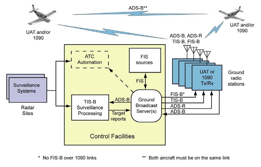
-
ADS-B Certification and Performance Requirements.
ADS-B equipment may be certified as a surveillance source for air traffic separation services using ADS-B Out. ADS-B equipment may also be certified for use with ADS-B In advisory services that enable appropriately equipped aircraft to display traffic and flight information. Refer to the aircraft's flight manual supplement or Pilot Operating Handbook for the capabilities of a specific aircraft installation. -
ADS-B Capabilities and Procedures.
-
ADS-B enables improved surveillance services, both air-to-air and air-to-ground, especially in areas where radar is ineffective due to terrain or where it is impractical or cost prohibitive. Initial NAS applications of air-to-air ADS-B are for “advisory” use only, enhancing a pilot's visual acquisition of other nearby equipped aircraft either when airborne or on the airport surface. Additionally, ADS-B will enable ATC and fleet operators to monitor aircraft throughout the available ground station coverage area.
FIG 4-5-7
En Route - ADS-B/ADS-R/TIS-B/FIS-B Service Ceilings/Floors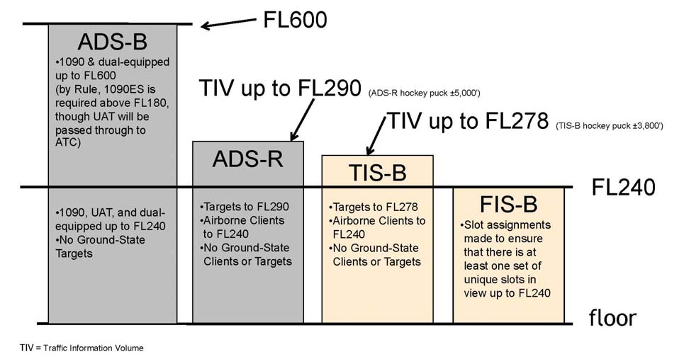
FIG 4-5-8
Terminal - ADS-B/ADS-R/TIS-B/FIS-B Service Ceilings/Floors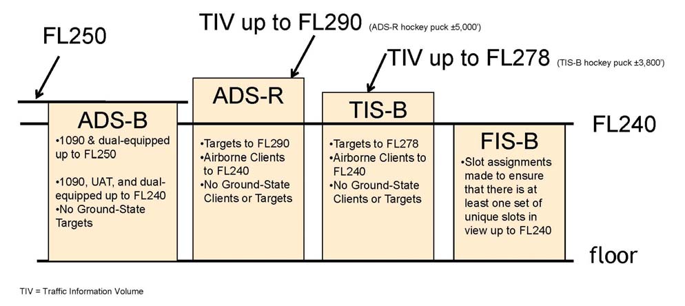
-
One of the data elements transmitted by ADS-B is the aircraft's Flight Identification (FLT ID). The FLT ID is comprised of a maximum of seven alphanumeric characters and must correspond to the aircraft identification filed in the flight plan. For airline and commuter aircraft, the FLT ID is usually the company name and flight number (for example, AAL3432), and is typically entered into the avionics by the flight crew during preflight. For general aviation (GA), if aircraft avionics allow dynamic modification of the FLT ID, the pilot can enter it prior to flight. However, some ADS-B avionics require the FLT ID to be set to the aircraft registration number (for example, N1234Q) by the installer and cannot be changed by the pilot from the cockpit. In both cases, the FLT ID must correspond to the aircraft identification filed in its flight plan.
ATC automation systems use the transmitted ADS-B FLT ID to uniquely identify each aircraft within a given airspace, and to correlate it to its filed flight plan for the purpose of providing surveillance and separation services. If the FLT ID and the filed aircraft identification are not identical, a Call Sign Mis-Match (CSMM) is generated and ATC automation systems may not associate the aircraft with its filed flight plan. In this case, air traffic services may be delayed or unavailable until the CSMM is corrected. Consequently, it is imperative that flight crews and GA pilots ensure the FLT ID entry correctly matches the aircraft identification filed in their flight plan. - Each ADS-B aircraft is assigned a unique ICAO address (also known as a 24-bit address) that is broadcast by the ADS-B transmitter. This ICAO address is programmed at installation. Should multiple aircraft broadcast the same ICAO address while transiting the same ADS-B Only Service Volume, the ADS-B network may be unable to track the targets correctly. If radar reinforcement is available, tracking will continue. If radar is unavailable, the controller may lose target tracking entirely on one or both targets. Consequently, it is imperative that the ICAO address entry is correct.
- Aircraft that are equipped with ADS-B avionics on the UAT datalink have a feature that allows them to broadcast an anonymous 24-bit ICAO address. In this mode, the UAT system creates a randomized address that does not match the actual ICAO address assigned to the aircraft. The UAT anonymous 24-bit address feature may only be used when the operator has not filed an IFR flight plan and is not requesting ATC services. In the anonymity mode, the aircraft's beacon code must be set to 1200 and, depending on the manufacturer's implementation, the aircraft FLT ID might not be transmitted. Pilots should be aware that while in UAT anonymity mode, they will not be eligible to receive ATC separation and flight following services, and may not benefit from enhanced ADS-B search and rescue capabilities.
- ADS-B systems integrated with the transponder will automatically set the applicable emergency status when 7500, 7600, or 7700 are entered into the transponder. ADS-B systems not integrated with the transponder, or systems with optional emergency codes, will require that the appropriate emergency code is entered through a pilot interface. ADS-B is intended for inflight and airport surface use. Unless otherwise directed by ATC, transponder/ADS-B systems should be turned “on” and remain “on” whenever operating in the air or on the airport surface movement area.
-
ADS-B enables improved surveillance services, both air-to-air and air-to-ground, especially in areas where radar is ineffective due to terrain or where it is impractical or cost prohibitive. Initial NAS applications of air-to-air ADS-B are for “advisory” use only, enhancing a pilot's visual acquisition of other nearby equipped aircraft either when airborne or on the airport surface. Additionally, ADS-B will enable ATC and fleet operators to monitor aircraft throughout the available ground station coverage area.
-
ATC Surveillance Services using ADS-B - Procedures and Recommended Phraseology
Radar procedures, with the exceptions found in this paragraph, are identical to those procedures prescribed for radar in AIM Chapter 4 and Chapter 5.-
Preflight:
If ATC services are anticipated when either a VFR or IFR flight plan is filed, the aircraft identification (as entered in the flight plan) must be entered as the FLT ID in the ADS-B avionics. -
Inflight:
When requesting surveillance services while airborne, pilots must disable the anonymous feature, if so equipped, prior to contacting ATC. Pilots must also ensure that their transmitted ADS-B FLT ID matches the aircraft identification as entered in their flight plan. -
Aircraft with an Inoperative/Malfunctioning ADS-B Transmitter:
-
ATC will inform the flight crew when the aircraft's ADS-B transmitter appears to be inoperative or malfunctioning:
PHRASEOLOGY-
YOUR ADS-B TRANSMITTER APPEARS TO BE INOPERATIVE/MALFUNCTIONING. STOP ADS-B TRANSMISSIONS.
-
ATC will inform the flight crew if it becomes necessary to turn off the aircraft's ADS-B transmitter.
PHRASEOLOGY-
STOP ADS-B TRANSMISSIONS.
-
Other malfunctions and considerations:
Loss of automatic altitude reporting capabilities (encoder failure) will result in loss of ATC altitude advisory services.
-
ATC will inform the flight crew when the aircraft's ADS-B transmitter appears to be inoperative or malfunctioning:
-
Procedures for Accommodation of Non-ADS-B Equipped Aircraft:
- Pilots of aircraft not equipped with ADS-B may only operate outside airspace designated as ADS-B airspace in 14 CFR §91.225. Pilots of unequipped aircraft wishing to fly any portion of a flight in ADS-B airspace may seek a deviation from the regulation to conduct operations without the required equipment. Direction for obtaining this deviation are available in Advisory Circular 90-114.
-
While air traffic controllers can identify which aircraft are ADS-B equipped and which are not, there is no indication if a non-equipped pilot has obtained a preflight authorization to enter ADS-B airspace. Situations may occur when the pilot of a non-equipped aircraft, without an authorization to operate in ADS-B airspace receives an ATC-initiated in-flight clearance to fly a heading, route, or altitude that would penetrate ADS-B airspace. Such clearances may be for traffic, weather, or simply to shorten the aircraft's route of flight. When this occurs, the pilot should acknowledge and execute the clearance, but must advise the controller that they are not ADS-B equipped and have not received prior authorization to operate in ADS-B airspace. The controller, at their discretion, will either acknowledge and proceed with the new clearance, or modify the clearance to avoid ADS-B airspace. In either case, the FAA will normally not take enforcement action for non-equipage in these circumstances.
NOTE-
Pilots operating without ADS-B equipment must not request route or altitude changes that will result in an incursion into ADS-B airspace except for safety of flight; for example, weather avoidance. Unequipped aircraft that have not received a pre-flight deviation authorization will only be considered in compliance with regulation if the amendment to flight is initiated by ATC.
EXAMPLE-
- ATC:
“November Two Three Quebec, turn fifteen degrees left, proceed direct Bradford when able, rest of route unchanged.”
Aircraft: “November Two Three Quebec, turning fifteen degrees left, direct Bradford when able, rest of route unchanged. Be advised, we are negative ADS-B equipment and have not received authorization to operate in ADS-B airspace.”
ATC: “November Two Three Quebec, roger”
or
“November Two Three Quebec, roger, turn twenty degrees right, rejoin Victor Ten, rest of route unchanged.” - ATC:
“November Four Alpha Tango, climb and maintain one zero thousand for traffic.”
Aircraft: “November Four Alpha Tango, leaving eight thousand for one zero thousand. Be advised, we are negative ADS-B equipment and have not received authorization to operate in ADS-B airspace.”
ATC: “November Four Alpha Tango, roger”
or
“November Four Alpha Tango, roger, cancel climb clearance, maintain eight thousand.”
REFERENCE-
Federal Register Notice, Volume 84, Number 62, dated April 1, 2019.
- ATC:
-
Preflight:
-
ADS-B Limitations.
The ADS-B cockpit display of traffic is NOT intended to be used as a collision avoidance system and does not relieve the pilot's responsibility to “see and avoid” other aircraft. (See paragraph 5-5-8, See and Avoid). ADS-B must not be used for avoidance maneuvers during IMC or other times when there is no visual contact with the intruder aircraft. ADS-B is intended only to assist in visual acquisition of other aircraft. No avoidance maneuvers are provided or authorized, as a direct result of an ADS-B target being displayed in the cockpit. -
Reports of ADS-B Malfunctions.
Users of ADS-B can provide valuable assistance in the correction of malfunctions by reporting instances of undesirable system performance. Since ADS-B performance is monitored by maintenance personnel rather than ATC, report malfunctions to the nearest Flight Service Station (FSS) facility by radio or telephone, or by sending an email to the ADS-B help desk at adsb@faa.gov. Reports should include:- Condition observed;
- Date and time of observation;
- Altitude and location of observation;
- Type and call sign of the aircraft; and
- Type and software version of avionics system.
-
Introduction.
-
Traffic Information Service- Broadcast (TIS-B)
-
Introduction
TIS-B is the broadcast of ATC derived traffic information to ADS-B equipped (1090ES or UAT) aircraft from ground radio stations. The source of this traffic information is derived from ground-based air traffic surveillance sensors. TIS-B service will be available throughout the NAS where there are both adequate surveillance coverage from ground sensors and adequate broadcast coverage from ADS-B ground radio stations. The quality level of traffic information provided by TIS-B is dependent upon the number and type of ground sensors available as TIS-B sources and the timeliness of the reported data. (See FIG 4-5-7 and FIG 4-5-8.) -
TIS-B Requirements.
In order to receive TIS-B service, the following conditions must exist:- Aircraft must be equipped with an ADS-B transmitter/receiver or transceiver, and a cockpit display of traffic information (CDTI).
- Aircraft must fly within the coverage volume of a compatible ground radio station that is configured for TIS-B uplinks. (Not all ground radio stations provide TIS-B due to a lack of radar coverage or because a radar feed is not available).
- Aircraft must be within the coverage of and detected by at least one ATC radar serving the ground radio station in use.
-
TIS-B Capabilities.
- TIS-B is intended to provide ADS-B equipped aircraft with a more complete traffic picture in situations where not all nearby aircraft are equipped with ADS-B Out. This advisory-only application is intended to enhance a pilot's visual acquisition of other traffic.
- Only transponder-equipped targets (i.e., Mode A/C or Mode S transponders) are transmitted through the ATC ground system architecture. Current radar siting may result in limited radar surveillance coverage at lower altitudes near some airports, with subsequently limited TIS-B service volume coverage. If there is no radar coverage in a given area, then there will be no TIS-B coverage in that area.
-
TIS-B Limitations.
-
TIS-B is NOT intended to be used as a collision avoidance system and does not relieve the pilot's responsibility to “see and avoid” other aircraft, in accordance with 14CFR §91.113b. TIS-B must not be used for avoidance maneuvers during times when there is no visual contact with the intruder aircraft. TIS-B is intended only to assist in the visual acquisition of other aircraft.
NOTE-
No aircraft avoidance maneuvers are authorized as a direct result of a TIS-B target being displayed in the cockpit.
-
While TIS-B is a useful aid to visual traffic avoidance, its inherent system limitations must be understood to ensure proper use.
- A pilot may receive an intermittent TIS-B target of themselves, typically when maneuvering (e.g., climbing turns) due to the radar not tracking the aircraft as quickly as ADS-B.
- The ADS-B-to-radar association process within the ground system may at times have difficulty correlating an ADS-B report with corresponding radar returns from the same aircraft. When this happens the pilot may see duplicate traffic symbols (i.e., “TIS-B shadows”) on the cockpit display.
- Updates of TIS-B traffic reports will occur less often than ADS-B traffic updates. TIS-B position updates will occur approximately once every 3-13 seconds depending on the type of radar system in use within the coverage area. In comparison, the update rate for ADS-B is nominally once per second.
- The TIS-B system only uplinks data pertaining to transponder-equipped aircraft. Aircraft without a transponder will not be displayed as TIS-B traffic.
- There is no indication provided when any aircraft is operating inside or outside the TIS-B service volume, therefore it is difficult to know if one is receiving uplinked TIS-B traffic information.
- Pilots and operators are reminded that the airborne equipment that displays TIS-B targets is for pilot situational awareness only and is not approved as a collision avoidance tool. Unless there is an imminent emergency requiring immediate action, any deviation from an air traffic control clearance in response to perceived converging traffic appearing on a TIS-B display must be approved by the controlling ATC facility before commencing the maneuver, except as permitted under certain conditions in 14CFR §91.123. Uncoordinated deviations may place an aircraft in close proximity to other aircraft under ATC control not seen on the airborne equipment and may result in a pilot deviation or other incident.
-
TIS-B is NOT intended to be used as a collision avoidance system and does not relieve the pilot's responsibility to “see and avoid” other aircraft, in accordance with 14CFR §91.113b. TIS-B must not be used for avoidance maneuvers during times when there is no visual contact with the intruder aircraft. TIS-B is intended only to assist in the visual acquisition of other aircraft.
-
Reports of TIS-B Malfunctions.
Users of TIS-B can provide valuable assistance in the correction of malfunctions by reporting instances of undesirable system performance. Since TIS-B performance is monitored by maintenance personnel rather than ATC, report malfunctions to the nearest Flight Service Station (FSS) facility by radio or telephone, or by sending an email to the ADS-B help desk at adsb@faa.gov. Reports should include:- Condition observed;
- Date and time of observation;
- Altitude and location of observation;
- Type and call sign of the aircraft; and
- Type and software version of avionics system.
-
Introduction
-
Flight Information Service- Broadcast (FIS-B)
-
Introduction.
FIS-B is a ground broadcast service provided through the ADS-B Services network over the 978 MHz UAT data link. The FAA FIS-B system provides pilots and flight crews of properly equipped aircraft with a cockpit display of certain aviation weather and aeronautical information. FIS-B reception is line-of-sight within the service volume of the ground infrastructure. (See FIG 4-5-7 and FIG 4-5-8.) -
Weather Products.
FIS-B does not replace a preflight weather briefing from a source listed in paragraph 7-1-2, FAA Weather Services, or inflight updates from an FSS or ATC. FIS-B information may be used by the pilot for the safe conduct of flight and aircraft movement; however, the information should not be the only source of weather or aeronautical information. A pilot should be particularly alert and understand the limitations and quality assurance issues associated with individual products. This includes graphical representation of next generation weather radar (NEXRAD) imagery and Notices to Airmen (NOTAMs)/temporary flight restrictions (TFRs).REFERENCE-
AIM, Para 7-1-9, Flight Information Services (FIS).
Advisory Circular (AC) 00-63, Use of Cockpit Displays of Digital Weather and Aeronautical Information. -
Reports of FIS-B Malfunctions.
Users of FIS-B can provide valuable assistance in the correction of malfunctions by reporting instances of undesirable system performance. Since FIS-B performance is monitored by maintenance personnel rather than ATC, report malfunctions to the nearest Flight Service Station (FSS) facility by radio or telephone, or by sending an email to the ADS-B help desk at adsb@faa.gov. Reports should include:- Condition observed;
- Date and time of observation;
- Altitude and location of observation;
- Type and call sign of the aircraft; and
-
Type and software version of avionics system.
TBL 4-5-3
FIS−B Over UAT Product Update and Transmission IntervalsProduct
Update Interval1
Transmission Interval (95%)2
Basic Product
AIRMET
As Available
5 minutes
Yes
AWW/WW
As Available, then at 15 minute intervals for 1 hour
5 minutes
No
Ceiling
As Available
10 minutes
No
Convective SIGMET
As Available, then at 15 minute intervals for 1 hour
5 minutes
Yes
D-ATIS
As Available
1 minute
No
Echo Top
5 minutes
5 minutes
No
METAR/SPECI
1 minute (where available), As Available otherwise
5 minutes
Yes
MRMS NEXRAD (CONUS)
2 minutes
15 minutes
Yes
MRMS NEXRAD (Regional)
2 minutes
2.5 minutes
Yes
NOTAMs-D/FDC
As Available
10 minutes
Yes
NOTAMs-TFR
As Available
10 minutes
Yes
PIREP
As Available
10 minutes
Yes
SIGMET
As Available, then at 15 minute intervals for 1 hour
5 minutes
Yes
SUA Status
As Available
10 minutes
Yes
TAF/AMEND
6 Hours (±15 minutes)
10 minutes
Yes
Temperature Aloft
12 Hours (±15 minutes)
10 minutes
Yes
TWIP
As Available
1 minute
No
Winds aloft
12 Hours (±15 minutes)
10 minutes
Yes
Lightning strikes 3
5 minutes
5 minutes
Yes
Turbulence 3
1 minute
15 minutes
Yes
Icing, Forecast Potential (FIP) 3
60 minutes
15 minutes
Yes
Cloud tops 3
30 minutes
15 minutes
Yes
1 Minute AWOS 3
1 minute
10 minutes
No
Graphical-AIRMET 3
As Available
5 minutes
Yes
Center Weather Advisory (CWA) 3
As Available
10 minutes
Yes
Temporary Restricted Areas (TRA)
As Available
10 minutes
Yes
Temporary Military Operations Areas (TMOA)
As Available
10 minutes
Yes
1The Update Interval is the rate at which the product data is available from the source.
2 The Transmission Interval is the amount of time within which a new or updated product transmission must be completed (95%) and the rate or repetition interval at which the product is rebroadcast (95%).
3 The transmission and update intervals for the expanded set of basic meteorological products may be adjusted based on FAA and vendor agreement on the final product formats and performance requirements.
NOTE-
- Details concerning the content, format, and symbols of the various data link products provided should be obtained from the specific avionics manufacturer.
- NOTAM-D and NOTAM-FDC products broadcast via FIS-B are limited to those issued or effective within the past 30 days.
-
Introduction.
-
Automatic Dependent Surveillance-Rebroadcast (ADS-R)
-
Introduction.
ADS-R is a datalink translation function of the ADS-B ground system required to accommodate the two separate operating frequencies (978 MHz and 1090 ES). The ADS-B system receives the ADS-B messages transmitted on one frequency and ADS-R translates and reformats the information for rebroadcast and use on the other frequency. This allows ADS-B In equipped aircraft to see nearby ADS-B Out traffic regardless of the operating link of the other aircraft. Aircraft operating on the same ADS-B frequency exchange information directly and do not require the ADS-R translation function. (See FIG 4-5-7 and FIG 4-5-8.) -
Reports of ADS-R Malfunctions.
Users of ADS-R can provide valuable assistance in the correction of malfunctions by reporting instances of undesirable system performance. Since ADS-R performance is monitored by maintenance personnel rather than ATC, report malfunctions to the nearest Flight Service Station (FSS) facility by radio or telephone, or by sending an email to the ADS-B help desk at adsb@faa.gov. Reports should include:- Condition observed;
- Date and time of observation;
- Altitude and location of observation;
- Type and call sign of the aircraft and;
- Type and software version of avionics system.
-
Introduction.