You have 0 items in your cart

FAR/AIM
>
Aeronautical Information Manual
>
Chapter 7. Safety of Flight
>
Section 6. Potential Flight Hazards
Section 6. Potential Flight Hazards
-
Accident Causal Factors
-
The 10 most frequent causal factors for general aviation accidents that involve the pilot‐in‐command are:
- Inadequate preflight preparation and/or planning.
- Failure to obtain and/or maintain flying speed.
- Failure to maintain direction control.
- Improper level off.
- Failure to see and avoid objects or obstructions.
- Mismanagement of fuel.
- Improper inflight decisions or planning.
- Misjudgment of distance and speed.
- Selection of unsuitable terrain.
- Improper operation of flight controls.
- This list remains relatively stable and points out the need for continued refresher training to establish a higher level of flight proficiency for all pilots. A part of the FAA's continuing effort to promote increased aviation safety is the Aviation Safety Program. For information on Aviation Safety Program activities contact your nearest Flight Standards District Office.
- Alertness. Be alert at all times, especially when the weather is good. Most pilots pay attention to business when they are operating in full IFR weather conditions, but strangely, air collisions almost invariably have occurred under ideal weather conditions. Unlimited visibility appears to encourage a sense of security which is not at all justified. Considerable information of value may be obtained by listening to advisories being issued in the terminal area, even though controller workload may prevent a pilot from obtaining individual service.
- Giving Way. If you think another aircraft is too close to you, give way instead of waiting for the other pilot to respect the right‐of‐way to which you may be entitled. It is a lot safer to pursue the right‐of‐way angle after you have completed your flight.
-
The 10 most frequent causal factors for general aviation accidents that involve the pilot‐in‐command are:
-
Reporting Radio/Radar Altimeter Anomalies
-
Background.
- The radio altimeter (also known as radar altimeter or RADALT) is a safety-critical aircraft system used to determine an aircraft's height above terrain. It is the only sensor onboard the aircraft capable of providing a direct measurement of the clearance height above the terrain and obstacles. Information from radio altimeters is essential for flight operations as a main enabler of several safety-critical functions and systems on the aircraft. The receiver on the radio altimeter is highly accurate because it is extremely sensitive, making it susceptible to radio frequency interference (RFI). RFI in the C-band portion of the spectrum could impact the functions of the radio altimeter during any phase of flight—most critically during takeoff, approach, and landing phases. This could pose a serious risk to flight safety.
- Installed radio altimeters normally supply critical height data to a wide range of automated safety systems, navigation systems, and cockpit displays. Harmful RFI affecting the radio altimeter can cause these safety and navigation systems to operate in unexpected ways and display erroneous information to the pilot. RFI can interrupt, or significantly degrade, radio altimeter functions—precluding radio altimeter-based terrain alerts and low-visibility approach and landing operations. Systems of concern include Terrain Awareness Warning Systems (TAWS), Enhanced Ground Proximity Warning Systems (EGPWS), and Traffic Collision Avoidance Systems (TCAS), to name a few. Pilots of radio altimeter equipped aircraft should become familiar with the radio altimeter's interdependence with the other aircraft systems and expected failure modes and indications that may be associated with harmful interference.
- Actions. Recognizing interference/anomalies in the radio altimeter can be difficult, as it may present as inoperative or erroneous data. Pilots need to monitor their automation, as well as their radio altimeters for discrepancies, and be prepared to take action. Pilots encountering radio altimeter interference/anomalies should transition to procedures that do not require the radio altimeter, and inform Air Traffic Control (ATC).
- Inflight Reporting. Pilots should report any radio altimeter anomaly to ATC as soon as practical.
-
Post Flight Reporting.
- Pilots are encouraged to submit detailed reports of radio altimeter interference/anomalies post flight as soon as practical, by internet via the Radio Altimeter Anomaly Reporting Form at https://www.faa.gov/air_traffic/nas/RADALT_reports/.
-
The post flight pilot reports of radio altimeter anomalies should contain as much of the following information as applicable:
- Date and time the anomaly was observed;
- Location of the aircraft at the time the anomaly started and ended (e.g., latitude, longitude or bearing/distance from a reference point or navigational aid);
- Magnetic heading;
- Altitude (MSL/AGL);
- Aircraft Type (make/model);
- Flight Number or Aircraft Registration Number;
- Meteorological conditions;
- Type of radio altimeter in use (e.g., make/model/software series or version), if known;
- Event overview;
- Consequences/operational impact (e.g., impacted equipment, actions taken to mitigate the disruption and/or remedy provided by ATC, required post flight pilot and maintenance actions).
-
Background.
-
VFR in Congested Areas
A high percentage of near midair collisions occur below 8,000 feet AGL and within 30 miles of an airport. When operating VFR in these highly congested areas, whether you intend to land at an airport within the area or are just flying through, it is recommended that extra vigilance be maintained and that you monitor an appropriate control frequency. Normally the appropriate frequency is an approach control frequency. By such monitoring action you can “get the picture” of the traffic in your area. When the approach controller has radar, radar traffic advisories may be given to VFR pilots upon request.
REFERENCE-
AIM, Para 4-1-15, Radar Traffic Information Service.
-
Obstructions To Flight
- General. Many structures exist that could significantly affect the safety of your flight when operating below 500 feet above ground level (AGL), and particularly below 200 feet AGL. While 14 CFR part 91.119 allows flight below 500 feet AGL when over sparsely populated areas or open water, such operations involve increased safety risks. At and below 200 feet AGL there are numerous power lines, antenna towers, etc., that are not marked and lighted and/or charted as obstructions and, therefore, may not be seen in time to avoid a collision. Notices to Airmen NOTAM are issued on those lighted structures experiencing temporary light outages. However, some time may pass before the FAA is notified of these outages, and the NOTAM issued, thus pilot vigilance is imperative. Additionally, new obstructions may not be on current charts because the information was not received prior to the FAA publishing the chart.
- Antenna Towers. Extreme caution should be exercised when flying less than 2,000 feet AGL because of numerous skeletal structures, such as radio and television antenna towers, that exceed 1,000 feet AGL with some extending higher than 2,000 feet AGL. Most skeletal structures are supported by guy wires which are very difficult to see in good weather and can be invisible at dusk or during periods of reduced visibility. These wires can extend about 1,500 feet horizontally from a structure; therefore, all skeletal structures should be avoided horizontally by at least 2,000 feet.
- Overhead Wires. Overhead transmission and utility lines often span approaches to runways, natural flyways such as lakes, rivers, gorges, and canyons, and cross other landmarks pilots frequently follow such as highways, railroad tracks, etc. As with antenna towers, these power transmission and/or utility lines and the supporting structures of these lines may not always be readily visible.The wires may be virtually impossible to see under certain conditions. Spherical markers may be used to identify overhead wires and catenary transmission lines and may be lighted. In some locations, the supporting structures of overhead transmission lines are equipped with unique sequence flashing white strobe light systems to indicate that there are wires between the structures. The flash sequence for the wire support structures will be middle, top, and bottom with all lights on the same level flashing simultaneously. However, not all power transmission and/or utility lines require notice to the FAA as they do not exceed 200 feet AGL or meet the obstruction standard of 14 CFR part 77 and, therefore, are not marked and/or lighted. All pilots are cautioned to remain extremely vigilant for power transmission and/or utility lines and their supporting structures when following natural flyways or during the approach and landing phase. This is particularly important for seaplane and/or float equipped aircraft when landing on, or departing from, unfamiliar lakes or rivers.
-
Wind Turbines. The number, size, and height of individual wind turbines and wind turbine farms have increased over time. The locations of wind turbine farms have also expanded to areas more commonly flown by VFR pilots and to all regions of the United States. VFR pilots should be aware that many wind turbines are exceeding 499 feet AGL in height, which may affect minimum safe VFR altitudes in uncontrolled airspace. In addition, many wind turbines are encroaching on the 700 foot AGL floor of controlled airspace (Class E). Pilots are cautioned to maintain appropriate safe distance (laterally, vertically, or both). Wind turbines are typically charted on Visual Flight Rules (VFR) Sectional Charts and/or Terminal Area Charts. For a description of how wind turbines and wind turbine farms are charted, refer to the FAA Aeronautical Chart User's Guide. Wind turbines are normally painted white or light gray to improve daytime conspicuity. They are typically lit with medium-intensity, flashing red lights, placed as high as possible on the turbine nacelle (not the blade tips), that should be synchronized to flash together; however, not all wind turbine units within a farm need to be lighted, depending on their location and height. Sometimes, only the perimeter of the wind turbine farm and an arrangement of interior wind turbines are lit. Some wind turbine farms use Aircraft Detection Lighting Systems (ADLS), which are proximity sensor-based systems designed to detect aircraft as they approach the obstruction. This system automatically activates the appropriate obstruction lights until they are no longer needed based on the position of the transiting aircraft. This technology reduces the impact of nighttime lighting on nearby communities and migratory birds and extends the life expectancy of the obstruction lights. For more information on how obstructions such as wind turbines are marked and lighted, refer to Advisory Circular 70/7460-1, Obstruction Marking and Lighting. Pilots should be aware that wind turbines in motion could result in limitations of air traffic services in the vicinity of the wind turbine farms.
REFERENCE-
AIM, Para 4-5-1, Radar.
- Meteorological (MET) Evaluation Towers. MET towers are used by wind energy companies to determine feasible sites for wind turbines. Some of these towers are less than 200 feet AGL. These structures are portable, erected in a matter of hours, installed with guyed wires, and constructed from a galvanized material often making them difficult to see in certain atmospheric conditions. Markings for these towers include alternating bands of aviation orange and white paint, and high-visibility sleeves installed on the outer guy wires. However, not all MET towers follow these guidelines, and pilots should be vigilant when flying at low altitude in remote or rural areas.
- Other Objects/Structures. There are other objects or structures that could adversely affect your flight such as temporary construction cranes near an airport, newly constructed buildings, new towers, etc. Many of these structures do not meet charting requirements or may not yet be charted because of the charting cycle. Some structures do not require obstruction marking and/or lighting, and some may not be marked and lighted even though the FAA recommended it. VFR pilots should carefully review NOTAMs for temporary or permanent obstructions along the planned route of flight during their preflight preparations. Particular emphasis should be given to obstructions in the vicinity of the approach and departure ends of the runway complex or any other areas where flight below 500 feet AGL is planned or likely to occur.
-
Avoid Flight Beneath Unmanned Balloons
- The majority of unmanned free balloons currently being operated have, extending below them, either a suspension device to which the payload or instrument package is attached, or a trailing wire antenna, or both. In many instances these balloon subsystems may be invisible to the pilot until the aircraft is close to the balloon, thereby creating a potentially dangerous situation. Therefore, good judgment on the part of the pilot dictates that aircraft should remain well clear of all unmanned free balloons and flight below them should be avoided at all times.
- Pilots are urged to report any unmanned free balloons sighted to the nearest FAA ground facility with which communication is established. Such information will assist FAA ATC facilities to identify and flight follow unmanned free balloons operating in the airspace.
-
Unmanned Aircraft Systems
- Unmanned Aircraft Systems (UAS), formerly referred to as “Unmanned Aerial Vehicles” (UAVs) or “drones,” are having an increasing operational presence in the NAS. Once the exclusive domain of the military, UAS are now being operated by various entities. Although these aircraft are “unmanned,” UAS are flown by a remotely located pilot and crew. Physical and performance characteristics of unmanned aircraft (UA) vary greatly and unlike model aircraft that typically operate lower than 400 feet AGL, UA may be found operating at virtually any altitude and any speed. Sizes of UA can be as small as several pounds to as large as a commercial transport aircraft. UAS come in various categories including airplane, rotorcraft, powered-lift (tilt-rotor), and lighter-than-air. Propulsion systems of UAS include a broad range of alternatives from piston powered and turbojet engines to battery and solar-powered electric motors.
- To ensure segregation of UAS operations from other aircraft, the military typically conducts UAS operations within restricted or other special use airspace. However, UAS operations are now being approved in the NAS outside of special use airspace through the use of FAA-issued Certificates of Waiver or Authorization (COA) or through the issuance of a special airworthiness certificate. COA and special airworthiness approvals authorize UAS flight operations to be contained within specific geographic boundaries and altitudes, usually require coordination with an ATC facility, and typically require the issuance of a NOTAM describing the operation to be conducted. UAS approvals also require observers to provide “see-and-avoid” capability to the UAS crew and to provide the necessary compliance with 14 CFR section 91.113. For UAS operations approved at or above FL180, UAS operate under the same requirements as that of manned aircraft (i.e., flights are operated under instrument flight rules, are in communication with ATC, and are appropriately equipped).
- UAS operations may be approved at either controlled or uncontrolled airports and are typically disseminated by NOTAM. In all cases, approved UAS operations must comply with all applicable regulations and/or special provisions specified in the COA or in the operating limitations of the special airworthiness certificate. At uncontrolled airports, UAS operations are advised to operate well clear of all known manned aircraft operations. Pilots of manned aircraft are advised to follow normal operating procedures and are urged to monitor the CTAF for any potential UAS activity. At controlled airports, local ATC procedures may be in place to handle UAS operations and should not require any special procedures from manned aircraft entering or departing the traffic pattern or operating in the vicinity of the airport.
- In addition to approved UAS operations described above, a recently approved agreement between the FAA and the Department of Defense authorizes small UAS operations wholly contained within Class G airspace, and in no instance, greater than 1200 feet AGL over military owned or leased property. These operations do not require any special authorization as long as the UA remains within the lateral boundaries of the military installation as well as other provisions including the issuance of a NOTAM. Unlike special use airspace, these areas may not be depicted on an aeronautical chart.
- There are several factors a pilot should consider regarding UAS activity in an effort to reduce potential flight hazards. Pilots are urged to exercise increased vigilance when operating in the vicinity of restricted or other special use airspace, military operations areas, and any military installation. Areas with a preponderance of UAS activity are typically noted on sectional charts advising pilots of this activity. Since the size of a UA can be very small, they may be difficult to see and track. If a UA is encountered during flight, as with manned aircraft, never assume that the pilot or crew of the UAS can see you, maintain increased vigilance with the UA and always be prepared for evasive action if necessary. Always check NOTAMs for potential UAS activity along the intended route of flight and exercise increased vigilance in areas specified in the NOTAM.
-
Mountain Flying
- Your first experience of flying over mountainous terrain (particularly if most of your flight time has been over the flatlands of the Midwest) could be a never‐to‐be‐forgotten nightmare if proper planning is not done and if you are not aware of the potential hazards awaiting. Those familiar section lines are not present in the mountains; those flat, level fields for forced landings are practically nonexistent; abrupt changes in wind direction and velocity occur; severe updrafts and downdrafts are common, particularly near or above abrupt changes of terrain such as cliffs or rugged areas; even the clouds look different and can build up with startling rapidity. Mountain flying need not be hazardous if you follow the recommendations below.
- File a Flight Plan. Plan your route to avoid topography which would prevent a safe forced landing. The route should be over populated areas and well known mountain passes. Sufficient altitude should be maintained to permit gliding to a safe landing in the event of engine failure.
- Don't fly a light aircraft when the winds aloft, at your proposed altitude, exceed 35 miles per hour. Expect the winds to be of much greater velocity over mountain passes than reported a few miles from them. Approach mountain passes with as much altitude as possible. Downdrafts of from 1,500 to 2,000 feet per minute are not uncommon on the leeward side.
- Don't fly near or above abrupt changes in terrain. Severe turbulence can be expected, especially in high wind conditions.
- Understand Mountain Obscuration. The term Mountain Obscuration (MTOS) is used to describe a visibility condition that is distinguished from IFR because ceilings, by definition, are described as “above ground level” (AGL). In mountainous terrain clouds can form at altitudes significantly higher than the weather reporting station and at the same time nearby mountaintops may be obscured by low visibility. In these areas the ground level can also vary greatly over a small area. Beware if operating VFR-on-top. You could be operating closer to the terrain than you think because the tops of mountains are hidden in a cloud deck below. MTOS areas are identified daily on The Aviation Weather Center located at: http://www.aviationweather.gov.
-
Navigating in confined terrain when flying through mountain passes can be challenging. For high-traffic mountain passes, VFR checkpoints may be provided on VFR navigation charts to increase situational awareness by indicating key landmarks inside confined terrain. A collocated VFR waypoint and checkpoint may be provided to assist with identifying natural entry points for commonly flown mountain passes. Pilots should reference the name of the charted VFR checkpoint, wherever possible, when making position reports on CTAF frequencies to reduce the risk of midair collisions. Pilots should evaluate the terrain along the route they intend to fly with respect to their aircraft type and performance capabilities, local weather, and their experience level to avoid flying into confined areas without adequate room to execute a 180 degree turn, should conditions require. Always fly with a planned escape route in mind.
REFERENCE-
AIM, Para 1-1-17, Global Positioning System (GPS).
- VFR flight operations may be conducted at night in mountainous terrain with the application of sound judgment and common sense. Proper pre‐flight planning, giving ample consideration to winds and weather, knowledge of the terrain and pilot experience in mountain flying are prerequisites for safety of flight. Continuous visual contact with the surface and obstructions is a major concern and flight operations under an overcast or in the vicinity of clouds should be approached with extreme caution.
- When landing at a high altitude field, the same indicated airspeed should be used as at low elevation fields. Remember: that due to the less dense air at altitude, this same indicated airspeed actually results in higher true airspeed, a faster landing speed, and more important, a longer landing distance. During gusty wind conditions which often prevail at high altitude fields, a power approach and power landing is recommended. Additionally, due to the faster groundspeed, your takeoff distance will increase considerably over that required at low altitudes.
-
Effects of Density Altitude. Performance figures in the aircraft owner's handbook for length of takeoff run, horsepower, rate of climb, etc., are generally based on standard atmosphere conditions (59 degrees Fahrenheit (15 degrees Celsius), pressure 29.92 inches of mercury) at sea level. However, inexperienced pilots, as well as experienced pilots, may run into trouble when they encounter an altogether different set of conditions. This is particularly true in hot weather and at higher elevations. Aircraft operations at altitudes above sea level and at higher than standard temperatures are commonplace in mountainous areas. Such operations quite often result in a drastic reduction of aircraft performance capabilities because of the changing air density. Density altitude is a measure of air density. It is not to be confused with pressure altitude, true altitude, or absolute altitude. It is not to be used as a height reference, but as a determining criteria in the performance capability of an aircraft. Air density decreases with altitude. As air density decreases, density altitude increases. The further effects of high temperature and high humidity are cumulative, resulting in an increasing high density altitude condition. High density altitude reduces all aircraft performance parameters. To the pilot, this means that the normal horsepower output is reduced, propeller efficiency is reduced, and a higher true airspeed is required to sustain the aircraft throughout its operating parameters. It means an increase in runway length requirements for takeoff and landings, and decreased rate of climb. An average small airplane, for example, requiring 1,000 feet for takeoff at sea level under standard atmospheric conditions will require a takeoff run of approximately 2,000 feet at an operational altitude of 5,000 feet.
NOTE-
A turbo‐charged aircraft engine provides a slight advantage in that it provides sea level horsepower up to a specified altitude above sea level.
- Density Altitude Advisories. At airports with elevations of 2,000 feet and higher, control towers and FSSs will broadcast the advisory “Check Density Altitude” when the temperature reaches a predetermined level. These advisories will be broadcast on appropriate tower frequencies or, where available, ATIS. FSSs will broadcast these advisories as a part of Local Airport Advisory.
-
These advisories are provided by air traffic facilities, as a reminder to pilots that high temperatures and high field elevations will cause significant changes in aircraft characteristics. The pilot retains the responsibility to compute density altitude, when appropriate, as a part of preflight duties.
NOTE-
All FSSs will compute the current density altitude upon request.
-
Mountain Wave. Many pilots go all their lives without understanding what a mountain wave is. Quite a few have lost their lives because of this lack of understanding. One need not be a licensed meteorologist to understand the mountain wave phenomenon.
- Mountain waves occur when air is being blown over a mountain range or even the ridge of a sharp bluff area. As the air hits the upwind side of the range, it starts to climb, thus creating what is generally a smooth updraft which turns into a turbulent downdraft as the air passes the crest of the ridge. From this point, for many miles downwind, there will be a series of downdrafts and updrafts. Satellite photos of the Rockies have shown mountain waves extending as far as 700 miles downwind of the range. Along the east coast area, such photos of the Appalachian chain have picked up the mountain wave phenomenon over a hundred miles eastward. All it takes to form a mountain wave is wind blowing across the range at 15 knots or better at an intersection angle of not less than 30 degrees.
- Pilots from flatland areas should understand a few things about mountain waves in order to stay out of trouble. When approaching a mountain range from the upwind side (generally the west), there will usually be a smooth updraft; therefore, it is not quite as dangerous an area as the lee of the range. From the leeward side, it is always a good idea to add an extra thousand feet or so of altitude because downdrafts can exceed the climb capability of the aircraft. Never expect an updraft when approaching a mountain chain from the leeward. Always be prepared to cope with a downdraft and turbulence.
- When approaching a mountain ridge from the downwind side, it is recommended that the ridge be approached at approximately a 45 degree angle to the horizontal direction of the ridge. This permits a safer retreat from the ridge with less stress on the aircraft should severe turbulence and downdraft be experienced. If severe turbulence is encountered, simultaneously reduce power and adjust pitch until aircraft approaches maneuvering speed, then adjust power and trim to maintain maneuvering speed and fly away from the turbulent area.
-
Use of Runway Half-way Signs at Unimproved Airports
When installed, runway half-way signs provide the pilot with a reference point to judge takeoff acceleration trends. Assuming that the runway length is appropriate for takeoff (considering runway condition and slope, elevation, aircraft weight, wind, and temperature), typical takeoff acceleration should allow the airplane to reach 70 percent of lift-off airspeed by the midpoint of the runway. The “rule of thumb” is that should airplane acceleration not allow the airspeed to reach this value by the midpoint, the takeoff should be aborted, as it may not be possible to liftoff in the remaining runway.
Several points are important when considering using this “rule of thumb”:
- Airspeed indicators in small airplanes are not required to be evaluated at speeds below stalling, and may not be usable at 70 percent of liftoff airspeed.
- This “rule of thumb” is based on a uniform surface condition. Puddles, soft spots, areas of tall and/or wet grass, loose gravel, etc., may impede acceleration or even cause deceleration. Even if the airplane achieves 70 percent of liftoff airspeed by the midpoint, the condition of the remainder of the runway may not allow further acceleration. The entire length of the runway should be inspected prior to takeoff to ensure a usable surface.
- This “rule of thumb” applies only to runway required for actual liftoff. In the event that obstacles affect the takeoff climb path, appropriate distance must be available after liftoff to accelerate to best angle of climb speed and to clear the obstacles. This will, in effect, require the airplane to accelerate to a higher speed by midpoint, particularly if the obstacles are close to the end of the runway. In addition, this technique does not take into account the effects of upslope or tailwinds on takeoff performance. These factors will also require greater acceleration than normal and, under some circumstances, prevent takeoff entirely.
-
Use of this “rule of thumb” does not alleviate the pilot's responsibility to comply with applicable Federal Aviation Regulations, the limitations and performance data provided in the FAA approved Airplane Flight Manual (AFM), or, in the absence of an FAA approved AFM, other data provided by the aircraft manufacturer.
In addition to their use during takeoff, runway half-way signs offer the pilot increased awareness of his or her position along the runway during landing operations.NOTE-
No FAA standard exists for the appearance of the runway half-way sign. FIG 7-6-1 shows a graphical depiction of a typical runway half-way sign.
FIG 7-6-1
Typical Runway Half-way Sign
-
Seaplane Safety
- Acquiring a seaplane class rating affords access to many areas not available to landplane pilots. Adding a seaplane class rating to your pilot certificate can be relatively uncomplicated and inexpensive. However, more effort is required to become a safe, efficient, competent “bush” pilot. The natural hazards of the backwoods have given way to modern man‐made hazards. Except for the far north, the available bodies of water are no longer the exclusive domain of the airman. Seaplane pilots must be vigilant for hazards such as electric power lines, power, sail and rowboats, rafts, mooring lines, water skiers, swimmers, etc.
- Seaplane pilots must have a thorough understanding of the right‐of‐way rules as they apply to aircraft versus other vessels. Seaplane pilots are expected to know and adhere to both the U.S. Coast Guard's (USCG) Navigation Rules, International-Inland, and 14 CFR section 91.115, Right-of-Way Rules; Water Operations. The navigation rules of the road are a set of collision avoidance rules as they apply to aircraft on the water. A seaplane is considered a vessel when on the water for the purposes of these collision avoidance rules. In general, a seaplane on the water must keep well clear of all vessels and avoid impeding their navigation. The CFR requires, in part, that aircraft operating on the water “. . . shall, insofar as possible, keep clear of all vessels and avoid impeding their navigation, and shall give way to any vessel or other aircraft that is given the right-of-way . . . .” This means that a seaplane should avoid boats and commercial shipping when on the water. If on a collision course, the seaplane should slow, stop, or maneuver to the right, away from the bow of the oncoming vessel. Also, while on the surface with an engine running, an aircraft must give way to all nonpowered vessels. Since a seaplane in the water may not be as maneuverable as one in the air, the aircraft on the water has right‐of‐way over one in the air, and one taking off has right‐of‐way over one landing. A seaplane is exempt from the USCG safety equipment requirements, including the requirements for Personal Flotation Devices (PFD). Requiring seaplanes on the water to comply with USCG equipment requirements in addition to the FAA equipment requirements would be an unnecessary burden on seaplane owners and operators.
- Unless they are under Federal jurisdiction, navigable bodies of water are under the jurisdiction of the state, or in a few cases, privately owned. Unless they are specifically restricted, aircraft have as much right to operate on these bodies of water as other vessels. To avoid problems, check with Federal or local officials in advance of operating on unfamiliar waters. In addition to the agencies listed in TBL 7-6-1, the nearest Flight Standards District Office can usually offer some practical suggestions as well as regulatory information. If you land on a restricted body of water because of an inflight emergency, or in ignorance of the restrictions you have violated, report as quickly as practical to the nearest local official having jurisdiction and explain your situation.
-
When operating a seaplane over or into remote areas, appropriate attention should be given to survival gear. Minimum kits are recommended for summer and winter, and are required by law for flight into sparsely settled areas of Canada and Alaska. Alaska State Department of Transportation and Canadian Ministry of Transport officials can provide specific information on survival gear requirements. The kit should be assembled in one container and be easily reachable and preferably floatable.
TBL 7-6-1
Jurisdictions Controlling Navigable Bodies of WaterAuthority to Consult For Use of a Body of Water
Location
Authority
Contact
Wilderness Area
U.S. Department of Agriculture, Forest Service
Local forest ranger
National Forest
USDA Forest Service
Local forest ranger
National Park
U.S. Department of the Interior, National Park Service
Local park ranger
Indian Reservation
USDI, Bureau of Indian Affairs
Local Bureau office
State Park
State government or state forestry or park service
Local state aviation office for further information
Canadian National and Provincial Parks
Supervised and restricted on an individual basis from province to province and by different departments of the Canadian government; consult Canadian Flight Information Manual and/or Water Aerodrome Supplement
Park Superintendent in an emergency
- The FAA recommends that each seaplane owner or operator provide flotation gear for occupants any time a seaplane operates on or near water. 14 CFR section 91.205(b)(12) requires approved flotation gear for aircraft operated for hire over water and beyond power‐off gliding distance from shore. FAA‐approved gear differs from that required for navigable waterways under USCG rules. FAA‐approved life vests are inflatable designs as compared to the USCG's noninflatable PFD's that may consist of solid, bulky material. Such USCG PFDs are impractical for seaplanes and other aircraft because they may block passage through the relatively narrow exits available to pilots and passengers. Life vests approved under Technical Standard Order (TSO) TSO-C13E contain fully inflatable compartments. The wearer inflates the compartments (AFTER exiting the aircraft) primarily by independent CO2 cartridges, with an oral inflation tube as a backup. The flotation gear also contains a water‐activated, self‐illuminating signal light. The fact that pilots and passengers can easily don and wear inflatable life vests (when not inflated) provides maximum effectiveness and allows for unrestricted movement. It is imperative that passengers are briefed on the location and proper use of available PFDs prior to leaving the dock.
- The FAA recommends that seaplane owners and operators obtain Advisory Circular (AC) 91-69, Seaplane Safety for 14 CFR part 91 Operations, free from the U.S. Department of Transportation, Subsequent Distribution Office, SVC-121.23, Ardmore East Business Center, 3341 Q 75th Avenue, Landover, MD 20785; fax: (301) 386-5394. The USCG Navigation Rules International-Inland (COMDTINSTM 16672.2B) is available for a fee from the Government Publishing Office by facsimile request to (202) 512-2250, and can be ordered using Mastercard or Visa.
-
Flight Operations in Volcanic Ash
- Severe volcanic eruptions which send ash and sulphur dioxide (SO2) gas into the upper atmosphere occur somewhere around the world several times each year. Flying into a volcanic ash cloud can be exceedingly dangerous. A B747-200 lost all four engines after such an encounter and a B747-400 had the same nearly catastrophic experience. Piston-powered aircraft are less likely to lose power but severe damage is almost certain to ensue after an encounter with a volcanic ash cloud which is only a few hours old.
- Most important is to avoid any encounter with volcanic ash. The ash plume may not be visible, especially in instrument conditions or at night; and even if visible, it is difficult to distinguish visually between an ash cloud and an ordinary weather cloud. Volcanic ash clouds are not displayed on airborne or ATC radar. The pilot must rely on reports from air traffic controllers and other pilots to determine the location of the ash cloud and use that information to remain well clear of the area. Additionally, the presence of a sulphur-like odor throughout the cabin may indicate the presence of SO2 emitted by volcanic activity, but may or may not indicate the presence of volcanic ash. Every attempt should be made to remain on the upwind side of the volcano.
-
It is recommended that pilots encountering an ash cloud should immediately reduce thrust to idle (altitude permitting), and reverse course in order to escape from the cloud. Ash clouds may extend for hundreds of miles and pilots should not attempt to fly through or climb out of the cloud. In addition, the following procedures are recommended:
- Disengage the autothrottle if engaged. This will prevent the autothrottle from increasing engine thrust;
- Turn on continuous ignition;
- Turn on all accessory airbleeds including all air conditioning packs, nacelles, and wing anti‐ice. This will provide an additional engine stall margin by reducing engine pressure.
-
The following has been reported by flightcrews who have experienced encounters with volcanic dust clouds:
- Smoke or dust appearing in the cockpit.
- An acrid odor similar to electrical smoke.
- Multiple engine malfunctions, such as compressor stalls, increasing EGT, torching from tailpipe, and flameouts.
- At night, St. Elmo's fire or other static discharges accompanied by a bright orange glow in the engine inlets.
- A fire warning in the forward cargo area.
- It may become necessary to shut down and then restart engines to prevent exceeding EGT limits. Volcanic ash may block the pitot system and result in unreliable airspeed indications.
- If you see a volcanic eruption and have not been previously notified of it, you may have been the first person to observe it. In this case, immediately contact ATC and alert them to the existence of the eruption. If possible, use the Volcanic Activity Reporting form (VAR) depicted in Appendix 2 of this manual. Items 1 through 8 of the VAR should be transmitted immediately. The information requested in items 9 through 16 should be passed after landing. If a VAR form is not immediately available, relay enough information to identify the position and nature of the volcanic activity. Do not become unnecessarily alarmed if there is merely steam or very low‐level eruptions of ash.
- When landing at airports where volcanic ash has been deposited on the runway, be aware that even a thin layer of dry ash can be detrimental to braking action. Wet ash on the runway may also reduce effectiveness of braking. It is recommended that reverse thrust be limited to minimum practical to reduce the possibility of reduced visibility and engine ingestion of airborne ash.
- When departing from airports where volcanic ash has been deposited, it is recommended that pilots avoid operating in visible airborne ash. Allow ash to settle before initiating takeoff roll. It is also recommended that flap extension be delayed until initiating the before takeoff checklist and that a rolling takeoff be executed to avoid blowing ash back into the air.
-
Emergency Airborne Inspection of Other Aircraft
- Providing airborne assistance to another aircraft may involve flying in very close proximity to that aircraft. Most pilots receive little, if any, formal training or instruction in this type of flying activity. Close proximity flying without sufficient time to plan (i.e., in an emergency situation), coupled with the stress involved in a perceived emergency can be hazardous.
- The pilot in the best position to assess the situation should take the responsibility of coordinating the airborne intercept and inspection, and take into account the unique flight characteristics and differences of the category(s) of aircraft involved.
-
Some of the safety considerations are:
- Area, direction and speed of the intercept;
- Aerodynamic effects (i.e., rotorcraft downwash);
- Minimum safe separation distances;
- Communications requirements, lost communications procedures, coordination with ATC;
- Suitability of diverting the distressed aircraft to the nearest safe airport; and
- Emergency actions to terminate the intercept.
- Close proximity, inflight inspection of another aircraft is uniquely hazardous. The pilot-in-command of the aircraft experiencing the problem/emergency must not relinquish control of the situation and/or jeopardize the safety of their aircraft. The maneuver must be accomplished with minimum risk to both aircraft.
-
Precipitation Static
- Precipitation static is caused by aircraft in flight coming in contact with uncharged particles. These particles can be rain, snow, fog, sleet, hail, volcanic ash, dust; any solid or liquid particles. When the aircraft strikes these neutral particles the positive element of the particle is reflected away from the aircraft and the negative particle adheres to the skin of the aircraft. In a very short period of time a substantial negative charge will develop on the skin of the aircraft. If the aircraft is not equipped with static dischargers, or has an ineffective static discharger system, when a sufficient negative voltage level is reached, the aircraft may go into “CORONA.” That is, it will discharge the static electricity from the extremities of the aircraft, such as the wing tips, horizontal stabilizer, vertical stabilizer, antenna, propeller tips, etc. This discharge of static electricity is what you will hear in your headphones and is what we call P-static.
-
A review of pilot reports often shows different symptoms with each problem that is encountered. The following list of problems is a summary of many pilot reports from many different aircraft. Each problem was caused by P-static:
- Complete loss of VHF communications.
- Erroneous magnetic compass readings (30 percent in error).
- High pitched squeal on audio.
- Motor boat sound on audio.
- Loss of all avionics in clouds.
- VLF navigation system inoperative most of the time.
- Erratic instrument readouts.
- Weak transmissions and poor receptivity of radios.
- “St. Elmo's Fire” on windshield.
- Each of these symptoms is caused by one general problem on the airframe. This problem is the inability of the accumulated charge to flow easily to the wing tips and tail of the airframe, and properly discharge to the airstream.
- Static dischargers work on the principal of creating a relatively easy path for discharging negative charges that develop on the aircraft by using a discharger with fine metal points, carbon coated rods, or carbon wicks rather than wait until a large charge is developed and discharged off the trailing edges of the aircraft that will interfere with avionics equipment. This process offers approximately 50 decibels (dB) static noise reduction which is adequate in most cases to be below the threshold of noise that would cause interference in avionics equipment.
- It is important to remember that precipitation static problems can only be corrected with the proper number of quality static dischargers, properly installed on a properly bonded aircraft. P-static is indeed a problem in the all weather operation of the aircraft, but there are effective ways to combat it. All possible methods of reducing the effects of P-static should be considered so as to provide the best possible performance in the flight environment.
- A wide variety of discharger designs is available on the commercial market. The inclusion of well-designed dischargers may be expected to improve airframe noise in P-static conditions by as much as 50 dB. Essentially, the discharger provides a path by which accumulated charge may leave the airframe quietly. This is generally accomplished by providing a group of tiny corona points to permit onset of corona-current flow at a low aircraft potential. Additionally, aerodynamic design of dischargers to permit corona to occur at the lowest possible atmospheric pressure also lowers the corona threshold. In addition to permitting a low-potential discharge, the discharger will minimize the radiation of radio frequency (RF) energy which accompanies the corona discharge, in order to minimize effects of RF components at communications and navigation frequencies on avionics performance. These effects are reduced through resistive attachment of the corona point(s) to the airframe, preserving direct current connection but attenuating the higher-frequency components of the discharge.
- Each manufacturer of static dischargers offers information concerning appropriate discharger location on specific airframes. Such locations emphasize the trailing outboard surfaces of wings and horizontal tail surfaces, plus the tip of the vertical stabilizer, where charge tends to accumulate on the airframe. Sufficient dischargers must be provided to allow for current-carrying capacity which will maintain airframe potential below the corona threshold of the trailing edges.
- In order to achieve full performance of avionic equipment, the static discharge system will require periodic maintenance. A pilot knowledgeable of P-static causes and effects is an important element in assuring optimum performance by early recognition of these types of problems.
-
Light Amplification by Stimulated Emission of Radiation (Laser) Operations and Reporting Illumination of Aircraft
- Lasers have many applications. Of concern to users of the National Airspace System are those laser events that may affect pilots, e.g., outdoor laser light shows or demonstrations for entertainment and advertisements at special events and theme parks. Generally, the beams from these events appear as bright blue-green in color; however, they may be red, yellow, or white. However, some laser systems produce light which is invisible to the human eye.
- FAA regulations prohibit the disruption of aviation activity by any person on the ground or in the air. The FAA and the Food and Drug Administration (the Federal agency that has the responsibility to enforce compliance with Federal requirements for laser systems and laser light show products) are working together to ensure that operators of these devices do not pose a hazard to aircraft operators.
- Pilots should be aware that illumination from these laser operations are able to create temporary vision impairment miles from the actual location. In addition, these operations can produce permanent eye damage. Pilots should make themselves aware of where these activities are being conducted and avoid these areas if possible.
- Recent and increasing incidents of unauthorized illumination of aircraft by lasers, as well as the proliferation and increasing sophistication of laser devices available to the general public, dictates that the FAA, in coordination with other government agencies, take action to safeguard flights from these unauthorized illuminations.
-
Pilots should report laser illumination activity to the controlling Air Traffic Control facilities, Federal Contract Towers or Flight Service Stations as soon as possible after the event. The following information should be included:
- UTC Date and Time of Event.
- Call Sign or Aircraft Registration Number.
- Type Aircraft.
- Nearest Major City.
- Altitude.
- Location of Event (Latitude/Longitude and/or Fixed Radial Distance (FRD)).
- Brief Description of the Event and any other Pertinent Information.
- Pilots are also encouraged to complete the Laser Beam Exposure Questionnaire located on the FAA Laser Safety Initiative website at http://www.faa.gov/about/initiatives/lasers/ and submit electronically per the directions on the questionnaire, as soon as possible after landing.
-
When a laser event is reported to an air traffic facility, a general caution warning will be broadcasted on all appropriate frequencies every five minutes for 20 minutes and broadcasted on the ATIS for one hour following the report.
PHRASEOLOGY-
UNAUTHORIZED LASER ILLUMINATION EVENT, (UTC time), (location), (altitude), (color), (direction).
EXAMPLE-
“Unauthorized laser illumination event, at 0100z, 8 mile final runway 18R at 3,000 feet, green laser from the southwest.”
REFERENCE-
FAA Order JO 7110.65, Para 10-2-14, Unauthorized Laser Illumination of Aircraft.
FAA Order JO 7210.3, Para 2-1-27, Reporting Unauthorized Laser Illumination of Aircraft. - When these activities become known to the FAA, Notices to Airmen (NOTAMs) are issued to inform the aviation community of the events. Pilots should consult NOTAMs or the Chart Supplement for information regarding these activities.
-
Flying in Flat Light, Brown Out Conditions, and White Out Conditions
- Flat Light. Flat light is an optical illusion, also known as “sector or partial white out.” It is not as severe as “white out” but the condition causes pilots to lose their depth-of-field and contrast in vision. Flat light conditions are usually accompanied by overcast skies inhibiting any visual clues. Such conditions can occur anywhere in the world, primarily in snow covered areas but can occur in dust, sand, mud flats, or on glassy water. Flat light can completely obscure features of the terrain, creating an inability to distinguish distances and closure rates. As a result of this reflected light, it can give pilots the illusion that they are ascending or descending when they may actually be flying level. However, with good judgment and proper training and planning, it is possible to safely operate an aircraft in flat light conditions.
-
Brown Out. A brownout (or brown-out) is an in-flight visibility restriction due to dust or sand in the air. In a brownout, the pilot cannot see nearby objects which provide the outside visual references necessary to control the aircraft near the ground. This can cause spatial disorientation and loss of situational awareness leading to an accident.
- The following factors will affect the probability and severity of brownout: rotor disk loading, rotor configuration, soil composition, wind, approach speed, and approach angle.
- The brownout phenomenon causes accidents during helicopter landing and take-off operations in dust, fine dirt, sand, or arid desert terrain. Intense, blinding dust clouds stirred up by the helicopter rotor downwash during near-ground flight causes significant flight safety risks from aircraft and ground obstacle collisions, and dynamic rollover due to sloped and uneven terrain.
- This is a dangerous phenomenon experienced by many helicopters when making landing approaches in dusty environments, whereby sand or dust particles become swept up in the rotor outwash and obscure the pilot's vision of the terrain. This is particularly dangerous because the pilot needs those visual cues from their surroundings in order to make a safe landing.
- Blowing sand and dust can cause an illusion of a tilted horizon. A pilot not using the flight instruments for reference may instinctively try to level the aircraft with respect to the false horizon, resulting in an accident. Helicopter rotor wash also causes sand to blow around outside the cockpit windows, possibly leading the pilot to experience an illusion where the helicopter appears to be turning when it is actually in a level hover. This can also cause the pilot to make incorrect control inputs which can quickly lead to disaster when hovering near the ground. In night landings, aircraft lighting can enhance the visual illusions by illuminating the brownout cloud.
- White Out. As defined in meteorological terms, white out occurs when a person becomes engulfed in a uniformly white glow. The glow is a result of being surrounded by blowing snow, dust, sand, mud or water. There are no shadows, no horizon or clouds and all depth-of-field and orientation are lost. A white out situation is severe in that there are no visual references. Flying is not recommended in any white out situation. Flat light conditions can lead to a white out environment quite rapidly, and both atmospheric conditions are insidious; they sneak up on you as your visual references slowly begin to disappear. White out has been the cause of several aviation accidents.
- Self Induced White Out. This effect typically occurs when a helicopter takes off or lands on a snow-covered area. The rotor down wash picks up particles and re-circulates them through the rotor down wash. The effect can vary in intensity depending upon the amount of light on the surface. This can happen on the sunniest, brightest day with good contrast everywhere. However, when it happens, there can be a complete loss of visual clues. If the pilot has not prepared for this immediate loss of visibility, the results can be disastrous. Good planning does not prevent one from encountering flat light or white out conditions.
-
Never take off in a white out situation.
- Realize that in flat light conditions it may be possible to depart but not to return to that site. During takeoff, make sure you have a reference point. Do not lose sight of it until you have a departure reference point in view. Be prepared to return to the takeoff reference if the departure reference does not come into view.
- Flat light is common to snow skiers. One way to compensate for the lack of visual contrast and depth-of-field loss is by wearing amber tinted lenses (also known as blue blockers). Special note of caution: Eyewear is not ideal for every pilot. Take into consideration personal factors—age, light sensitivity, and ambient lighting conditions.
-
So what should a pilot do when all visual references are lost?
- Trust the cockpit instruments.
- Execute a 180 degree turnaround and start looking for outside references.
- Above all - fly the aircraft.
- Landing in Low Light Conditions. When landing in a low light condition - use extreme caution. Look for intermediate reference points, in addition to checkpoints along each leg of the route for course confirmation and timing. The lower the ambient light becomes, the more reference points a pilot should use.
-
Airport Landings.
- Look for features around the airport or approach path that can be used in determining depth perception. Buildings, towers, vehicles or other aircraft serve well for this measurement. Use something that will provide you with a sense of height above the ground, in addition to orienting you to the runway.
- Be cautious of snowdrifts and snow banks - anything that can distinguish the edge of the runway. Look for subtle changes in snow texture or shading to identify ridges or changes in snow depth.
-
Off-Airport Landings.
-
In the event of an off-airport landing, pilots have used a number of different visual cues to gain reference. Use whatever you must to create the contrast you need. Natural references seem to work best (trees, rocks, snow ribs, etc.)
- Over flight.
- Use of markers.
- Weighted flags.
- Smoke bombs.
- Any colored rags.
- Dye markers.
- Kool-aid.
- Trees or tree branches.
- It is difficult to determine the depth of snow in areas that are level. Dropping items from the aircraft to use as reference points should be used as a visual aid only and not as a primary landing reference. Unless your marker is biodegradable, be sure to retrieve it after landing. Never put yourself in a position where no visual references exist.
- Abort landing if blowing snow obscures your reference. Make your decisions early. Don't assume you can pick up a lost reference point when you get closer.
- Exercise extreme caution when flying from sunlight into shade. Physical awareness may tell you that you are flying straight but you may actually be in a spiral dive with centrifugal force pressing against you. Having no visual references enhances this illusion. Just because you have a good visual reference does not mean that it's safe to continue. There may be snow-covered terrain not visible in the direction that you are traveling. Getting caught in a no visual reference situation can be fatal.
-
In the event of an off-airport landing, pilots have used a number of different visual cues to gain reference. Use whatever you must to create the contrast you need. Natural references seem to work best (trees, rocks, snow ribs, etc.)
-
Flying Around a Lake.
- When flying along lakeshores, use them as a reference point. Even if you can see the other side, realize that your depth perception may be poor. It is easy to fly into the surface. If you must cross the lake, check the altimeter frequently and maintain a safe altitude while you still have a good reference. Don't descend below that altitude.
- The same rules apply to seemingly flat areas of snow. If you don't have good references, avoid going there.
- Other Traffic. Be on the look out for other traffic in the area. Other aircraft may be using your same reference point. Chances are greater of colliding with someone traveling in the same direction as you, than someone flying in the opposite direction.
- Ceilings. Low ceilings have caught many pilots off guard. Clouds do not always form parallel to the surface, or at the same altitude. Pilots may try to compensate for this by flying with a slight bank and thus creating a descending turn.
- Glaciers. Be conscious of your altitude when flying over glaciers. The glaciers may be rising faster than you are climbing.
-
Operations in Ground Icing Conditions
-
The presence of aircraft airframe icing during takeoff, typically caused by improper or no deicing of the aircraft being accomplished prior to flight has contributed to many recent accidents in turbine aircraft. The General Aviation Joint Steering Committee (GAJSC) is the primary vehicle for government-industry cooperation, communication, and coordination on GA accident mitigation. The Turbine Aircraft Operations Subgroup (TAOS) works to mitigate accidents in turbine accident aviation. While there is sufficient information and guidance currently available regarding the effects of icing on aircraft and methods for deicing, the TAOS has developed a list of recommended actions to further assist pilots and operators in this area.
While the efforts of the TAOS specifically focus on turbine aircraft, it is recognized that their recommendations are applicable to and can be adapted for the pilot of a small, piston powered aircraft too. -
The following recommendations are offered:
- Ensure that your aircraft's lift-generating surfaces are COMPLETELY free of contamination before flight through a tactile (hands on) check of the critical surfaces when feasible. Even when otherwise permitted, operators should avoid smooth or polished frost on lift-generating surfaces as an acceptable preflight condition.
- Review and refresh your cold weather standard operating procedures.
- Review and be familiar with the Airplane Flight Manual (AFM) limitations and procedures necessary to deal with icing conditions prior to flight, as well as in flight.
- Protect your aircraft while on the ground, if possible, from sleet and freezing rain by taking advantage of aircraft hangars.
- Take full advantage of the opportunities available at airports for deicing. Do not refuse deicing services simply because of cost.
- Always consider canceling or delaying a flight if weather conditions do not support a safe operation.
-
If you haven't already developed a set of Standard Operating Procedures for cold weather operations, they should include:
- Procedures based on information that is applicable to the aircraft operated, such as AFM limitations and procedures;
- Concise and easy to understand guidance that outlines best operational practices;
- A systematic procedure for recognizing, evaluating and addressing the associated icing risk, and offer clear guidance to mitigate this risk;
- An aid (such as a checklist or reference cards) that is readily available during normal day-to-day aircraft operations.
-
There are several sources for guidance relating to airframe icing, including:
- http://aircrafticing.grc.nasa.gov/index.html
- Advisory Circular (AC) 91-74, Pilot Guide, Flight in Icing Conditions.
- AC 135-17, Pilot Guide Small Aircraft Ground Deicing.
- AC 135-9, FAR Part 135 Icing Limitations.
- AC 120-60, Ground Deicing and Anti-icing Program.
- AC 135-16, Ground Deicing and Anti-icing Training and Checking. The FAA Approved Deicing Program Updates is published annually as a Flight Standards Information Bulletin for Air Transportation and contains detailed information on deicing and anti-icing procedures and holdover times. It may be accessed at the following website by selecting the current year's information bulletins: https://www.faa.gov/other_visit/aviation_industry/airline_operators/airline_safety/deicing/.
-
The presence of aircraft airframe icing during takeoff, typically caused by improper or no deicing of the aircraft being accomplished prior to flight has contributed to many recent accidents in turbine aircraft. The General Aviation Joint Steering Committee (GAJSC) is the primary vehicle for government-industry cooperation, communication, and coordination on GA accident mitigation. The Turbine Aircraft Operations Subgroup (TAOS) works to mitigate accidents in turbine accident aviation. While there is sufficient information and guidance currently available regarding the effects of icing on aircraft and methods for deicing, the TAOS has developed a list of recommended actions to further assist pilots and operators in this area.
-
Avoid Flight in the Vicinity of Exhaust Plumes (Smoke Stacks and Cooling Towers)
-
Flight Hazards Exist Around Exhaust Plumes. Exhaust plumes are defined as visible or invisible emissions from power plants, industrial production facilities, or other industrial systems that release large amounts of vertically directed unstable gases (effluent). High temperature exhaust plumes can cause significant air disturbances such as turbulence and vertical shear. Other identified potential hazards include, but are not necessarily limited to: reduced visibility, oxygen depletion, engine particulate contamination, exposure to gaseous oxides, and/or icing. Results of encountering a plume may include airframe damage, aircraft upset, and/or engine damage/failure. These hazards are most critical during low altitude flight in calm and cold air, especially in and around approach and departure corridors or airport traffic areas.
Whether plumes are visible or invisible, the total extent of their turbulent affect is difficult to predict. Some studies do predict that the significant turbulent effects of an exhaust plume can extend to heights of over 1,000 feet above the height of the top of the stack or cooling tower. Any effects will be more pronounced in calm stable air where the plume is very hot and the surrounding area is still and cold. Fortunately, studies also predict that any amount of crosswind will help to dissipate the effects. However, the size of the tower or stack is not a good indicator of the predicted effect the plume may produce. The major effects are related to the heat or size of the plume effluent, the ambient air temperature, and the wind speed affecting the plume. Smaller aircraft can expect to feel an effect at a higher altitude than heavier aircraft. -
When able, a pilot should steer clear of exhaust plumes by flying on the upwind side of smokestacks or cooling towers. When a plume is visible via smoke or a condensation cloud, remain clear and realize a plume may have both visible and invisible characteristics. Exhaust stacks without visible plumes may still be in full operation, and airspace in the vicinity should be treated with caution. As with mountain wave turbulence or clear air turbulence, an invisible plume may be encountered unexpectedly. Cooling towers, power plant stacks, exhaust fans, and other similar structures are depicted in FIG 7-6-2.
Pilots are encouraged to exercise caution when flying in the vicinity of exhaust plumes. Pilots are also encouraged to reference the Chart Supplement where amplifying notes may caution pilots and identify the location of structure(s) emitting exhaust plumes.
The best available information on this phenomenon must come from pilots via the PIREP reporting procedures. All pilots encountering hazardous plume conditions are urgently requested to report time, location, and intensity (light, moderate, severe, or extreme) of the element to the FAA facility with which they are maintaining radio contact. If time and conditions permit, elements should be reported according to the standards for other PIREPs and position reports (AIM paragraph 7-1-21, PIREPS Relating to Turbulence).FIG 7-6-2
Plumes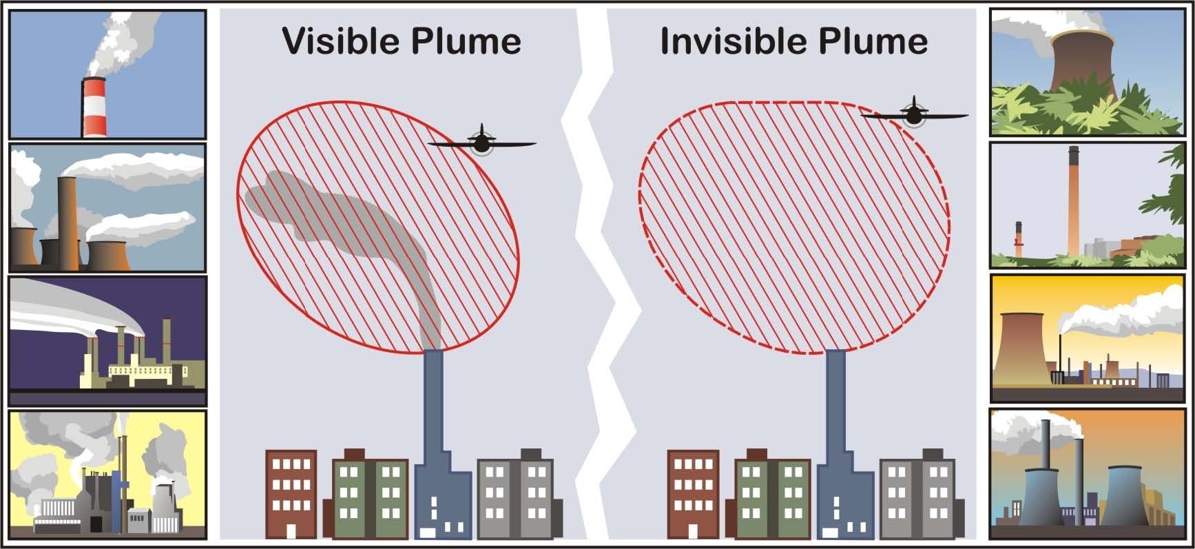
-
Flight Hazards Exist Around Exhaust Plumes. Exhaust plumes are defined as visible or invisible emissions from power plants, industrial production facilities, or other industrial systems that release large amounts of vertically directed unstable gases (effluent). High temperature exhaust plumes can cause significant air disturbances such as turbulence and vertical shear. Other identified potential hazards include, but are not necessarily limited to: reduced visibility, oxygen depletion, engine particulate contamination, exposure to gaseous oxides, and/or icing. Results of encountering a plume may include airframe damage, aircraft upset, and/or engine damage/failure. These hazards are most critical during low altitude flight in calm and cold air, especially in and around approach and departure corridors or airport traffic areas.
-
Space Launch and Reentry Area
Locations where commercial space launch and/or reentry operations occur. Hazardous operations occur in space launch and reentry areas, and for pilot awareness, a rocket-shaped symbol is used to depict them on sectional aeronautical charts. These locations may have vertical launches from launch pads, horizontal launches from runways, and/or reentering vehicles coming back to land. Because of the wide range of hazards associated with space launch and reentry areas, pilots are expected to check NOTAMs for the specific area prior to flight to determine the location and lateral boundaries of the associated hazard area, and the active time. NOTAMs may include terms such as “rocket launch activity,” “space launch," or “space reentry,” depending upon the type of operation. Space launch and reentry areas are not established for amateur rocket operations conducted per 14 CFR part 101.
FIG 7-6-3
Space Launch and Reentry Area Depicted on a Sectional Chart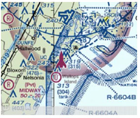
-
Automatic Landing Operations
Prior to conducting automatic landing operations, pilots are expected to determine that the flight control and instrument approach guidance systems being used permit safe, automatically flown landings to be conducted at that runway. The analysis should include, but not be limited to, ILS classification code where applicable, suitable threshold crossing height, runway slope, and pre-threshold terrain. The FAA only evaluates runways and other ground infrastructure for suitability to support automatic landing operations for those facilities associated with published CAT II, SA CAT II, and CAT III instrument approach procedures. When conducting automatic landing operations, pilots must ensure that the runway, associated procedure, navigation source, and other infrastructure have no outstanding NOTAMs or chart notes that would preclude automatic landing operations (e.g., “Localizer unusable inside the threshold,” or “Glide slope unusable below xxx feet”). Pilots should advise ATC of their intent to conduct an automatic landing, remain alert to any unsuitable system performance, and be prepared to disengage the automatic landing system when necessary. During automatic landing operations using an ILS facility, pilots should understand and observe the provisions of AIM, subparagraph 1-1-9k, ILS Course and Glideslope Distortion.