You have 0 items in your cart

Chapter 5. Air Traffic Procedures
- Section 1. Preflight
- Section 2. Departure Procedures
- Section 3. En Route Procedures
- Section 4. Arrival Procedures
- Section 5. Pilot/Controller Roles and Responsibilities
- Section 6. National Security and Interception Procedures
Section 1. Preflight
-
Preflight Preparation
-
Prior to every flight, pilots should gather all information vital to the nature of the flight, assess whether the flight would be safe, and then file a flight plan. Pilots can receive a regulatory compliant briefing without contacting Flight Service. Pilots are encouraged to use automated resources and review Advisory Circular AC 91-92, Pilot's Guide to a Preflight Briefing, for more information. Pilots who prefer to contact Flight Service are encouraged to conduct a self-brief prior to calling. Conducting a self-brief before contacting Flight Service provides familiarity of meteorological and aeronautical conditions applicable to the route of flight and promotes a better understanding of weather information. Pilots may access Flight Service through www.1800wxbrief.com or by calling 1-800-WX-BRIEF. Flight planning applications are also available for conducting a self-briefing and filing flight plans.
NOTE-
Alaska only: Pilots filing flight plans via “fast file” who desire to have their briefing recorded, should include a statement at the end of the recording as to the source of their weather briefing.
-
The information required by the FAA to process flight plans is obtained from FAA Form 7233-4, International Flight Plan. Only DoD users, and civilians who file stereo route flight plans, may use FAA Form 7233-1, Flight Plan.
NOTE-
FAA and DoD Flight Plan Forms are equivalent. Where the FAA specifies Form 7233-1, Flight Plan and FAA Form 7233-4, International Flight Plan, the DoD may substitute their Form DD 175, Military Flight Plan and Form DD-1801, DoD International Flight Plan as necessary. NAS automation systems process and convert data in the same manner, although for computer acceptance, input fields may be adjusted to follow FAA format.
-
FSSs are required to advise of pertinent NOTAMs if a standard briefing is requested, but if they are overlooked, do not hesitate to remind the specialist that you have not received NOTAM information. Additionally, FSS briefers do not provide FDC NOTAM information for special instrument approach procedures unless specifically asked. Pilots authorized by the FAA to use special instrument approach procedures must specifically request FDC NOTAM information for these procedures. Pilots who receive the information electronically will receive NOTAMs for special IAPs automatically.
NOTE-
Domestic Notices and International Notices are not provided during a briefing unless specifically requested by the pilot since the FSS specialist has no way of knowing whether the pilot has already checked the Federal NOTAM System (FNS) NOTAM Search website external links prior to calling. Airway NOTAMs, procedural NOTAMs, and NOTAMs that are general in nature and not tied to a specific airport/facility (for example, flight advisories and restrictions, open duration special security instructions, and special flight rules areas) are briefed solely by pilot request. Remember to ask for these notices if you have not already reviewed this information, and to request all pertinent NOTAMs specific to your flight.
REFERENCE-
-
Pilots are urged to use only the latest issue of aeronautical charts in planning and conducting flight operations. Aeronautical charts are revised and reissued on a regular scheduled basis to ensure that depicted data are current and reliable. In the conterminous U.S., Sectional Charts are updated every 56 days, IFR En Route Charts every 56 days, and amendments to civil IFR Approach Charts are accomplished on a 56-day cycle with a change notice volume issued on the 28-day midcycle. Charts that have been superseded by those of a more recent date may contain obsolete or incomplete flight information.
REFERENCE-
AIM, Para 9-1-5, General Description of Each Chart Series.
-
When requesting a preflight briefing, identify yourself as a pilot and provide the following:
- Type of flight planned; e.g., VFR or IFR.
- Aircraft's number or pilot's name.
- Aircraft type.
- Departure Airport.
- Route of flight.
- Destination.
- Flight altitude(s).
- ETD and ETE.
-
Prior to conducting a briefing, briefers are required to have the background information listed above so that they may tailor the briefing to the needs of the proposed flight. The objective is to communicate a “picture” of meteorological and aeronautical information necessary for the conduct of a safe and efficient flight. Briefers use all available weather and aeronautical information to summarize data applicable to the proposed flight. Pilots who have briefed themselves before calling Flight Service should advise the briefer what information has been obtained from other sources.
REFERENCE-
AIM, Para 7-1-5, Preflight Briefings, contains those items of a weather briefing that should be expected or requested.
-
FAA by 14 CFR part 93, Subpart K, has designated High Density Traffic Airports (HDTA) and has prescribed air traffic rules and requirements for operating aircraft (excluding helicopter operations) to and from these airports.
REFERENCE-
Chart Supplement, Special Notices Section.
AIM, Para 4-1-21, Airport Reservation Operations and Special Traffic Management Programs. -
In addition to the filing of a flight plan, if the flight will traverse or land in one or more foreign countries, it is particularly important that pilots leave a complete itinerary with someone directly concerned and keep that person advised of the flight's progress. If serious doubt arises as to the safety of the flight, that person should first contact the FSS.
REFERENCE-
AIM, Para 5-1-11, Flights Outside the U.S. and U.S. Territories.
-
Pilots operating under provisions of 14 CFR part 135 on a domestic flight without having an FAA assigned 3-letter designator, must prefix the normal registration (N) number with the letter “T” on flight plan filing; for example, TN1234B.
REFERENCE-
AIM, Para 4-2-4, Aircraft Call Signs.
FAA Order JO 7110.65, Para 2-3-5, Aircraft Identity, Subpara a.
FAA Order JO 7110.10, Appendix B, FAA Form 7233-1, Flight Plan
-
Prior to every flight, pilots should gather all information vital to the nature of the flight, assess whether the flight would be safe, and then file a flight plan. Pilots can receive a regulatory compliant briefing without contacting Flight Service. Pilots are encouraged to use automated resources and review Advisory Circular AC 91-92, Pilot's Guide to a Preflight Briefing, for more information. Pilots who prefer to contact Flight Service are encouraged to conduct a self-brief prior to calling. Conducting a self-brief before contacting Flight Service provides familiarity of meteorological and aeronautical conditions applicable to the route of flight and promotes a better understanding of weather information. Pilots may access Flight Service through www.1800wxbrief.com or by calling 1-800-WX-BRIEF. Flight planning applications are also available for conducting a self-briefing and filing flight plans.
-
Follow IFR Procedures Even When Operating VFR
-
To maintain IFR proficiency, pilots are urged to practice IFR procedures whenever possible, even when operating VFR. Some suggested practices include:
- Obtain a complete preflight briefing and check NOTAMs. Prior to every flight, pilots should gather all information vital to the nature of the flight. Pilots can receive a regulatory compliant briefing without contacting Flight Service. Pilots are encouraged to use automated resources and review AC 91-92, Pilot's Guide to a Preflight Briefing, for more information. NOTAMs are available online from the Federal NOTAM System (FNS) NOTAM Search website ( https://notams.aim.faa.gov/notamSearch/ ), private vendors, or on request from Flight Service.
- File a flight plan. This is an excellent low cost insurance policy. The cost is the time it takes to fill it out. The insurance includes the knowledge that someone will be looking for you if you become overdue at your destination. Pilots can file flight plans either by using a website or by calling Flight Service. Flight planning applications are also available to file, activate, and close VFR flight plans.
- Use current charts.
- Use the navigation aids. Practice maintaining a good course-keep the needle centered.
- Maintain a constant altitude which is appropriate for the direction of flight.
- Estimate en route position times.
- Make accurate and frequent position reports to the FSSs along your route of flight.
- Simulated IFR flight is recommended (under the hood); however, pilots are cautioned to review and adhere to the requirements specified in 14 CFR section 91.109 before and during such flight.
- When flying VFR at night, in addition to the altitude appropriate for the direction of flight, pilots should maintain an altitude which is at or above the minimum en route altitude as shown on charts. This is especially true in mountainous terrain, where there is usually very little ground reference. Do not depend on your eyes alone to avoid rising unlighted terrain, or even lighted obstructions such as TV towers.
-
To maintain IFR proficiency, pilots are urged to practice IFR procedures whenever possible, even when operating VFR. Some suggested practices include:
-
Notice to Airmen (NOTAM) System
- General. The NOTAM system provides pilots with time critical aeronautical information that is temporary, or information to be published on aeronautical charts at a later date, or information from another operational publication. The NOTAM is cancelled when the information in the NOTAM is published on the chart or when the temporary condition is returned to normal status. NOTAMs may be disseminated up to 7 days before the start of activity. Pilots can access NOTAM information online via NOTAM Search at: https://notams.aim.faa.gov/notamSearch/ or from an FSS.
-
Preflight. 14 CFR § 91.103, Preflight Action directs pilots to become familiar with all available information concerning a planned flight prior to departure, including NOTAMs.Pilots may change their flight plan based on available information. Current NOTAM information may affect:
- Aerodromes.
- Runways, taxiways, and ramp restrictions.
- Obstructions.
- Communications.
- Airspace.
- Status of navigational aids or radar service availability.
- Other information essential to planned en route, terminal, or landing operations.
-
ARTCC NOTAMs. Pilots should also review NOTAMs for the ARTCC area (for example, Washington Center (ZDC), Cleveland Center (ZOB), etc.) in which the flight will be operating. You can find the 3 letter code for each ARTCC on the FAA's NOTAM webpage. These NOTAMs may affect the planned flight. Some of the operations include Central Altitude Reservation Function (CARF), Special Use Airspace (SUA), Temporary Flight Restrictions (TFR), Global Positioning System (GPS), Flight Data Center (FDC) changes to routes, wind turbine, and Unmanned Aircraft System (UAS).
NOTE-
NOTAM information is transmitted using ICAO contractions to reduce transmission time. See TBL 5-1-2 for a listing of the most commonly used contractions, or go online to the following URL:
https://www.notams.faa.gov/downloads/contractions.pdf. For a complete listing of approved NOTAM Contractions, see FAA Order JO 7340.2, Contractions. - Destination Update. Pilots should also contact ATC or FSS while en route to obtain updated airfield information for their destination. This is particularly important when flying to the airports without an operating control tower. Snow removal, fire and rescue activities, construction, and wildlife encroachment, may pose hazards to pilots. This information may not be available to pilots prior to arrival/departure.
- NAVAID NOTAMs. Pilots should check NOTAMs to ensure NAVAIDs required for the flight are in service. A NOTAM is published when a NAVAID is out of service or Unserviceable (U/S). Although a NAVAID is deemed U/S and planned for removal from service, it may be a long time before that NAVAID is officially decommissioned and removed from charts. A NOTAM is the primary method of alerting pilots to its unavailability. Pilots using VFR charts can also review the Aeronautical Information Services' (AIS) website concerning Safety Alerts, Charting Notices, and Digital Product Notices at https://www.faa.gov/air_traffic/flight_info/aeronav/safety_alerts/ for additional chart information.
-
GPS NOTAMs. The FAA issues information on the status of GPS through the NOTAM system. Operators may find information on GPS satellite outages, GPS testing, and GPS anomalies by specifically searching for GPS NOTAMS prior to flight.
-
The NOTAM system uses the terms UNRELIABLE (UNREL), MAY NOT BE AVAILABLE (AVBL), and NOT AVAILABLE (AVBL) when describing the status of GPS. UNREL indicates the expected level of service of the GPS and/or WAAS may not be available. Pilots must then determine the adequacy of the signal for desired use. Aircraft should have additional navigation equipment for their intended route.
NOTE-
Unless associated with a known testing NOTAM, pilots should report GPS anomalies, including degraded operation and/or loss of service, as soon as possible via radio or telephone, and via the GPS Anomaly Reporting Form. (See 1-1-13.)
- GPS operations may also be NOTAMed for testing. This is indicated in the NOTAM language with the name of the test in parenthesis. When GPS testing NOTAMS are published and testing is actually occurring, ATC will advise pilots requesting or cleared for a GPS or RNAV (GPS) approach, that GPS may not be available and request the pilot's intentions. TBL 5-1-1 lists an example of a GPS testing NOTAM.
-
The NOTAM system uses the terms UNRELIABLE (UNREL), MAY NOT BE AVAILABLE (AVBL), and NOT AVAILABLE (AVBL) when describing the status of GPS. UNREL indicates the expected level of service of the GPS and/or WAAS may not be available. Pilots must then determine the adequacy of the signal for desired use. Aircraft should have additional navigation equipment for their intended route.
-
NOTAM Classification. NOTAM information is classified as Domestic NOTAMs (NOTAM D), Flight Data Center (FDC) NOTAMs, International NOTAMs, or Military NOTAMs.
-
NOTAM (D) information is disseminated for all navigational facilities that are part of the National Airspace System (NAS), all public use aerodromes, seaplane bases, and heliports listed in the Chart Supplement. NOTAM (D) information includes taxiway closures, personnel and equipment near or crossing runways, and airport lighting aids that do not affect instrument approach criteria (i.e., VGSI). All NOTAM Ds must have one of the keywords listed in TBL 5-1-1, as the first part of the text after the location identifier. These keywords categorize NOTAM Ds by subject, for example, APRON (ramp), RWY (runway), SVC (Services), etc. There are several types of NOTAM Ds:
- Aerodrome activity and conditions, to include field conditions.
- Airspace to include CARF, SUA, and general airspace activity like UAS or pyrotechnics.
- Visual and radio navigational aids.
- Communication and services.
- Pointer NOTAMs. NOTAMs issued to point to additional aeronautical information. When pointing to another NOTAM, the keyword in the pointer NOTAM must match the keyword in the original NOTAM. Pointer NOTAMs should be issued for, but are not limited to, TFRs, Airshows, Temporary SUA, major NAS system interruptions, etc.
-
FDC NOTAMs are issued when it is necessary to disseminate regulatory information. FDC NOTAMs include:
- Amendments to published IAPs and other current aeronautical charts.
- Temporary Flight Restrictions (TFR) restrict entrance to a certain airspace at a certain time, however, some TFRs provide relief if ATC permission is given to enter the area when requested. Online preflight resources for TFRs provide graphics and plain language interpretations.
- High barometric pressure warning.
- Laser light activity.
- ADS-B, TIS-B, and FIS-B service availability.
- Satellite-based systems such as WAAS or GPS.
- Special Notices.
-
International NOTAMs are published in ICAO format per Annex 15 and distributed to multiple countries.
- International NOTAMs issued by the U.S. NOTAM Office use Series A followed by 4 sequential numbers, a slant “/” and a 2-digit number representing the year the NOTAM was issued. International NOTAMs basically duplicate data found in a U.S. Domestic NOTAM.
- Not every topic of a U.S. Domestic NOTAM is issued as an International NOTAM by the U.S. The U.S. International NOTAM will be linked to the appropriate U.S. Domestic NOTAM when possible.
- International NOTAMs received by the FAA from other countries are stored in the U.S. NOTAM System.
-
The International NOTAM format includes a “Q” Line that can be easily read/parsed by a computer and allows the NOTAM to be displayed digitally.
- Field A: ICAO location identifier or FIR affected by the NOTAM.
- Field B: Start of Validity.
- Field C: End of Validity (both in [Year][Month][Day][Hour][Minute] format).
- Field D: (when present) Schedule.
- Field E: Full NOTAM description.
- Field F: (when present) Lowest altitude, or “SFC.”
- Field G: (when present) Highest altitude, or “UNL.”
- For more on International format, please see Annex 15.
- Military NOTAMs are NOTAMs originated by the U.S. Air Force, Army, Marine, or Navy, and pertaining to military or joint-use navigational aids/airports that are part of the NAS. Military NOTAMs are published in the International NOTAM format and should be reviewed by users of a military or joint-use facility.
-
NOTAM (D) information is disseminated for all navigational facilities that are part of the National Airspace System (NAS), all public use aerodromes, seaplane bases, and heliports listed in the Chart Supplement. NOTAM (D) information includes taxiway closures, personnel and equipment near or crossing runways, and airport lighting aids that do not affect instrument approach criteria (i.e., VGSI). All NOTAM Ds must have one of the keywords listed in TBL 5-1-1, as the first part of the text after the location identifier. These keywords categorize NOTAM Ds by subject, for example, APRON (ramp), RWY (runway), SVC (Services), etc. There are several types of NOTAM Ds:
-
Security NOTAMS:
- U.S. Domestic Security NOTAMS are FDC NOTAMS that inform pilots of certain U.S. security activities or requirements, such as Special Security Instructions for aircraft operations to, from, within, or transitioning U.S. territorial airspace. These NOTAMS are found on the Federal NOTAM System (FNS) NOTAM Search website under the location designator KZZZ.
-
United States International Flight Prohibitions, Potential Hostile Situations, and Foreign Notices are issued by the FAA and are found on the Federal NOTAM System (FNS) NOTAM Search website under the location designator KICZ.
TBL 5-1-1
NOTAM KeywordsKeyword
Definition
RWY
Example
Runway
!BNA BNA RWY 18/36 CLSD YYMMDDHHMM-YYMMDDHHMMTWY
Example
Taxiway
!BTV BTV TWY C EDGE LGT OBSC YYMMDDHHMM-YYMMDDHHMMAPRON
Example
Apron/Ramp
!BNA BNA APRON NORTH APN E 100FT CLSD YYMMDDHHMM-YYMMDDHHMMAD
Example
Aerodrome
!BET BET AD AP ELK NEAR MOVEMENT AREAS YYMMDDHHMM-YYMMDDHHMMOBST
Example
Obstruction
!SJT SJT OBST MOORED BALLOON WI AN AREA DEFINED AS 1NM RADIUS OF SJT 2430FT (510FT AGL) FLAGGED YYMMDDHHMM-YYMMDDHHMMNAV
Example
Navigation Aids
!SHV SHV NAV ILS RWY 32 110.3 COMMISSIONED YYMMDDHHMM-PERMCOM
Example
Communications
!INW INW COM REMOTE COM OUTLET 122.6 U/S YYMMDDHHMM-YYMMDDHHMM EST
(Note* EST will auto cancel)SVC
Example
Services
!ROA ROA SVC TWR COMMISSIONED YYMMDDHHMM-PERMAIRSPACE
Example
Airspace
!MHV MHV AIRSPACE AEROBATIC ACFT WI AN AREA DEFINED AS 4.3NM RADIUS OF MHV 5500FT-10500FT AVOIDANCE ADZ CTC JOSHUA APP DLY YYMMDDHHMM-YYMMDDHHMMODP
Example
Obstacle Departure Procedure
!FDC 2/9700 DIK ODP DICKINSON - THEODORE ROOSEVELT RGNL, DICKINSON, ND. TAKEOFF MINIMUMS AND (OBSTACLE) DEPARTURE PROCEDURES AMDT 1... DEPARTURE PROCEDURE: RWY 25, CLIMB HEADING 250 TO 3500 BEFORE TURNING LEFT. ALL OTHER DATA REMAINS AS PUBLISHED. THIS IS TAKEOFF MINIMUMS AND (OBSTACLE) DEPARTURE PROCEDURES, AMDT 1A. YYMMDDHHMM-PERMSID
Example
Standard Instrument Departure
!FDC x/xxxx DFW SID DALLAS/FORT WORTH INTL, DALLAS, TX. PODDE THREE DEPARTURE... CHANGE NOTES TO READ: RWYS 17C/R, 18L/R: DO NOT EXCEED 240KT UNTIL LARRN. RWYS 35L/C, 36L/R: DO NOT EXCEED 240KT UNTIL KMART YYMMDDHHMM-YYMMDDHHMMSTAR
Example
Standard Terminal Arrival
!FDC x/xxxx DCA STAR RONALD REAGAN WASHINGTON NATIONAL, WASHINGTON, DC. WZRRD TWO ARRIVAL... SHAAR TRANSITION: ROUTE FROM DRUZZ INT TO WZRRD INT NOT AUTHORIZED. AFTER DRUZZ INT EXPECT RADAR VECTORS TO AML VORTAC YYMMDDHHMM-YYMMDDHHMMCHART
Example
Chart
!FDC 2/9997 DAL IAP DALLAS LOVE FIELD, DALLAS, TX. ILS OR LOC RWY 31R, AMDT 5... CHART NOTE: SIMULTANEOUS APPROACH AUTHORIZED WITH RWY 31L. MISSED APPROACH: CLIMB TO 1000 THEN CLIMBING RIGHT TURN TO 5000 ON HEADING 330 AND CVE R-046 TO FINGR INT/CVE 36.4 DME AND HOLD. CHART LOC RWY 31L. THIS IS ILS OR LOC RWY 31R, AMDT 5A. YYMMDDHHMM-PERMDATA
Example
Data
!FDC 2/9700 DIK ODP DICKINSON - THEODORE ROOSEVELT RGNL, DICKINSON, ND. TAKEOFF MINIMUMS AND (OBSTACLE) DEPARTURE PROCEDURES AMDT 1... DEPARTURE PROCEDURE: RWY 25, CLIMB HEADING 250 TO 3500 BEFORE TURNING LEFT. ALL OTHER DATA REMAINS AS PUBLISHED. THIS IS TAKEOFF MINIMUMS AND (OBSTACLE) DEPARTURE PROCEDURES, AMDT 1A. YYMMDDHHMM-PERMIAP
Example
Instrument Approach Procedure
!FDC 2/9997 DAL IAP DALLAS LOVE FIELD, DALLAS, TX. ILS OR LOC RWY 31R, AMDT 5... CHART NOTE: SIMULTANEOUS APPROACH AUTHORIZED WITH RWY 31L. MISSED APPROACH: CLIMB TO 1000 THEN CLIMBING RIGHT TURN TO 5000 ON HEADING 330 AND CVE R-046 TO FINGR INT/CVE 36.4 DME AND HOLD. CHART LOC RWY 31L. THIS IS ILS OR LOC RWY 31R, AMDT 5A. YYMMDDHHMM-PERMVFP
Example
Visual Flight Procedures
!FDC X/XXXX JFK VFP JOHN F KENNEDY INTL, NEW YORK, NY. PARKWAY VISUAL RWY 13L/R, ORIG...WEATHER MINIMUMS 3000 FOOT CEILING AND 3 MILES VISIBILITY. YYMMDDHHMM-YYMMDDHHMMROUTE
Example
Route
!FDC x/xxxx ZFW ROUTE ZFW ZKC. V140 SAYRE (SYO) VORTAC, OK TO TULSA (TUL) VORTAC, OK MEA 4300. YYMMDDHHMM-YYMMDDHHMM ESTSPECIAL
Example
Special
!FDC x/xxxx JNU SPECIAL JUNEAU INTERNATIONAL, JUNEAU, AK. LDA-2 RWY 8 AMDT 9 PROCEDURE TURN NA. YYMMDDHHMM-YYMMDDHHMMSECURITY
Example
Security
!FDC x/xxxx FDC ...SPECIAL NOTICE... THIS IS A RESTATEMENT OF A PREVIOUSLY ISSUED ADVISORY NOTICE. IN THE INTEREST OF NATIONAL SECURITY AND TO THE EXTENT PRACTICABLE, PILOTS ARE STRONGLY ADVISED TO AVOID THE AIRSPACE ABOVE, OR IN PROXIMITY TO SUCH SITES AS POWER PLANTS (NUCLEAR, HYDRO-ELECTRIC, OR COAL), DAMS, REFINERIES, INDUSTRIAL COMPLEXES, MILITARY FACILITIES AND OTHER SIMILAR FACILITIES. PILOTS SHOULD NOT CIRCLE AS TO LOITER IN THE VICINITY OVER THESE TYPES OF FACILITIES.GPS TESTING Example
Global Positioning System Testing
!GPS 01/028 ZAB NAV GPS (YPG_AZ GPS 21-06)(INCLUDING WAAS, GBAS, AND ADS-B) MAYNOT BE AVBL WI A276NM RADIUS CENTERED AT 332347N1142221W
(BLH108023) FL400-UNL,
232NM RADIUS AT FL250,
164NM RADIUS AT 100000FT
160NM RADIUS AT 4000FT AGL
126NM RADIUS AT 50FT AGL
DLY 1830-2230
2101281830-2101292230PRN (GPS) Example
Pseudo-random noise code used to differentiate GPS satellites. This code allows any receiver to identify exactly which satellite(s) it is receiving.
!GPS GPS NAV PRN 16 U/S 2109231600-2109242300ESTTBL 5-1-2
Contractions Commonly Found in NOTAMsA
ABN
Aerodrome Beacon
ACFT
Aircraft
ACT
Active
ADJ
Adjacent
AGL
Above Ground Level
ALS
Approach Light System
AP
Airport
APN
Apron
APP
Approach control office or approach control or approach control service
ARST
Arresting (specify (part of) aircraft arresting equipment)
ASDA
Accelerate Stop Distance Available
ASPH
Asphalt
AUTH
Authorized or authorization
AVBL
Available or availability
AVGAS
Aviation gasoline
AWOS
Automatic Weather Observing System
AZM
Azimuth
B
BA
Braking action
BCN
Beacon (aeronautical ground light)
BCST
Broadcast
BDRY
Boundary
BLDG
Building
BLW
Below
BTN
Between
C
C
Center (preceded by runway designator number to identify a parallel runway)
CD
Clearance delivery
CIV
Civil
CL
Centerline
CLSD
Close or closed or closing
COM
Communication
CONC
Concrete
COND
Condition
CONS
Continuous
CONST
Construction or constructed
CPDLC
Controller Pilot Data Link Communications
CTC
Contact
CUST
Customs
D
DA
Decision altitude
DEG
Degrees
DEP
Depart or Departure
DER
Departure end of the runway
DH
Decision Height
DIST
Distance
DLY
Daily
DP
Dew Point Temperature
DPT
Depth
DTHR
Displaced Runway Threshold
E
E
East or eastern longititude
EB
Eastbound
EMERG
Emergency
ENE
East-northeast
EQPT
Equipment
ESE
East-southeast
EST
Estimate or estimated or estimation (message type designator)
EXC
Except
F
FL
Flight level
FREQ
Frequency
FRI
Friday
FSS
Flight Service Station
FST
First
FT
Feet (dimensional unit)
G
G
Green
GA
General aviation
GLD
Glider
GND
Ground
GP
Glide Path
GRVL
Gravel
H
HEL
Helicopter
HGT
Height or height above
HLDG
Holding
HLP
Heliport
HVY
Heavy
I
IFR
Instrument Flight Rules
ILS
Instrument Landing System
IM
Inner Marker
INOP
Inoperative
INT
Intersection
K
KT
Knots
L
L
Left (preceded by runway designator number to identify a parallel runway)
LAT
Latitude
LDA
Landing Distance Available
LDG
Landing
LEN
Length
LGT
Light or lighting
LGTD
Lighted
LOC
Localizer
LONG
Longitude
M
MAINT
Maintenance
MBST
Microburst
MIL
Military
MIN
Minutes
MNT
Monitor or monitoring or monitored
MON
Monday
MOV
Move or moving or movement
N
N
North
NAVAID
Navigational aid
NB
Northbound
NDB
Nondirectional Radio Beacon
NE
Northeast
NEB
Northeast bound
NM
Nautical Mile/s
NNE
North-northeast
NNW
North-northwest
NOV
November
NW
Northwest
NWB
Northwest bound
O
OBSC
Obscure or obscured or obscuring
OBST
Obstacle
OPN
Open or opening or opened
OPS
Operations
P
PAPI
Precision Approach Path Indicator
PARL
Parallel
PAX
Passenger/s
PCL
Pilot Controlled Lighting
PCT
Percent
PERM
Permanent
PJE
Parachute Jumping Activities
PLA
Practice Low Approach
PPR
Prior Permission Required
PRN
Pseudo-random Navigation
PT
Procedure Turn
R
R
Red
R
Right (preceded by runway designator number to identify a parallel runway)
RAI
Runway Alignment Indicator
RCL
Runway Centerline
RCLL
Runway Centerline Light
REDL
Runway Edge Light
RLLS
Runway Lead-in Light System
RMK
Remark
RTS
Return to Service
RTZL
Runway Touchdown Zone Light(s)
RVR
Runway Visual Range
RWY
Runway
RX
Receive/Receiver
S
S
South or southern latitude
SA
Sand
SAT
Saturday
SB
Southbound
SE
Southeast
SEC
Seconds
SFC
Surface
SN
Snow
SR
Sunrise
SS
Sunset
SSR
Secondary surveillance radar
SSW
South-southwest
STD
Standard
SUN
Sunday
SW
Southwest
SWB
Southwest bound
T
TAR
Terminal area surveillance radar
TAX
Taxing or taxiing
TDZ
Touchdown Zone
TEMPO
Temporary or temporarily
TFC
Traffic
THR
Threshold
THU
Thursday
TKOF
Takeoff
TODA
Take-off Distance Available
TORA
Take-off Run Available
TRG
Training
TUE
Tuesday
TWR
Aerodrome Control Tower
TWY
Taxiway
TX
Taxilane
U
U/S
Unserviceable
UAS
Unmanned Aircraft System
UNL
Unlimited
UNREL
Unreliable
V
VIS
Visibility
VOR
VHF Omni‐Directional Radio Range
VORTAC
VOR and TACAN (collocated)
VOT
VOR Test Facility
W
W
West or western longitude
WB
Westbound
WDI
Wind Direction Indicator
WED
Wednesday
WI
Within
WID
Width or wide
WIP
Work in progress
WNW
West-northwest
WS
Wind shear
WSW
West-southwest
-
Operational Information System (OIS)
- The FAA's Air Traffic Control System Command Center (ATCSCC) maintains a website with near real-time National Airspace System (NAS) status information. NAS operators are encouraged to access the website at http://www.fly.faa.gov prior to filing their flight plan.
-
The website consolidates information from advisories. An advisory is a message that is disseminated electronically by the ATCSCC that contains information pertinent to the NAS.
-
Advisories are normally issued for the following items:
- Ground Stops.
- Ground Delay Programs.
- Route Information.
- Plan of Operations.
- Facility Outages and Scheduled Facility Outages.
- Volcanic Ash Activity Bulletins.
- Special Traffic Management Programs.
- This list is not all-inclusive. Any time there is information that may be beneficial to a large number of people, an advisory may be sent. Additionally, there may be times when an advisory is not sent due to workload or the short length of time of the activity.
- Route information is available on the website and in specific advisories. Some route information, subject to the 56-day publishing cycle, is located on the “OIS” under “Products,” Route Management Tool (RMT), and “What's New” Playbook. The RMT and Playbook contain routings for use by Air Traffic and NAS operators when they are coordinated “real-time” and are then published in an ATCSCC advisory.
- Route advisories are identified by the word “Route” in the header; the associated action is required (RQD), recommended (RMD), planned (PLN), or for your information (FYI). Operators are expected to file flight plans consistent with the Route RQD advisories.
- Electronic System Impact Reports are on the intranet at http://www.atcscc.faa.gov/ois/ under “System Impact Reports." This page lists scheduled outages/events/projects that significantly impact the NAS; for example, runway closures, air shows, and construction projects. Information includes anticipated delays and traffic management initiatives (TMI) that may be implemented.
-
Advisories are normally issued for the following items:
-
Flight Plan - VFR Flights
(See Appendix 4, FAA Form 7233-4 - International Flight Plan)
-
The requirements for the filing and activation of VFR flight plans can vary depending in which airspace the flight is operating. Pilots are responsible for activating flight plans with a Flight Service Station. Control tower personnel do not automatically activate VFR flight plans.
- Within the continental U.S., a VFR flight plan is not normally required.
-
VFR flights (except for DoD and law enforcement flights) into an Air Defense Identification Zone (ADIZ) are required to file DVFR flight plans.
NOTE-
Detailed ADIZ procedures are found inSection 6, National Security and Interception Procedures, of this chapter. (See 14 CFR part 99).
- Flights within the Washington, DC Special Flight Rules Area have additional requirements that must be met. Visit http://www.faasafety.gov for the required Special Awareness Training that must be completed before flight within this area.
-
VFR flight to an international destination requires a filed and activated flight plan.
NOTE-
ICAO flight plan guidance is published in ICAO Document 4444 PANS-ATM Appendix 2.
- It is strongly recommended that a VFR flight plan be filed with a Flight Service Station or equivalent flight plan filing service. When filing, pilots must use FAA Form 7233-4, International Flight Plan or DD Form 1801. Only DoD users, and civilians who file stereo route flight plans, may use FAA Form 7233-1, Flight Plan. Pilots may take advantage of advances in technology by filing their flight plans using any available electronic means. Activating the flight plan will ensure that you receive VFR Search and Rescue services.
- When a stopover flight is anticipated, it is recommended that a separate flight plan be filed for each leg of the flight.
- Pilots are encouraged to activate their VFR flight plans with Flight Service by the most expeditious means possible. This may be via radio or other electronic means. VFR flight plan proposals are normally retained for two hours following the proposed time of departure.
-
Pilots may also activate a VFR flight plan by using an assumed departure time. This assumed departure time will cause the flight plan to become active at the designated time. This may negate the need for communication with a flight service station or flight plan filing service upon departure. It is the pilot's responsibility to revise his actual departure time, time en route, or ETA with flight service.
NOTE-
Pilots are strongly advised to remain mindful when using an assumed departure time. If not updated, search and rescue activities will be based on the assumed departure time.
- U.S. air traffic control towers do not routinely activate VFR flight plans. Foreign pilots especially must be mindful of the need to communicate directly with a flight service station, or use an assumed departure time procedure clearly communicated with the flight plan filing service.
- Although position reports are not required for VFR flight plans, periodic reports to FSSs along the route are good practice. Such contacts permit significant information to be passed to the transiting aircraft and also serve to check the progress of the flight should it be necessary for any reason to locate the aircraft.
- Pilots flying VFR should fly an appropriate cruising altitude for their direction of flight.
-
When filing a VFR Flight plan, indicate the appropriate aircraft equipment capability as prescribed for an IFR flight plan.
REFERENCE-
AIM, Para 5-1-6, IFR Flights.
- ATC radar history data can be useful in finding a downed or missing aircraft; therefore, surveillance equipment should be listed in Item 18. Pilots using commercial GPS tracking services are encouraged to note the specific service in Item 19 N/ (survival equip remarks) of FAA Form 7233-4 or DD Form 1801.
-
The requirements for the filing and activation of VFR flight plans can vary depending in which airspace the flight is operating. Pilots are responsible for activating flight plans with a Flight Service Station. Control tower personnel do not automatically activate VFR flight plans.
-
Flight Plan - IFR Flights
(See Appendix 4, FAA Form 7233-4 - International Flight Plan)
-
General
- Use of FAA Form 7233-4 or DD Form 1801 is mandatory for:
- Military/DoD flights using FAA Form 7233-1, or DD Form 175, may not be eligible for assignment of RNAV SIDs or STARs. Military flights desiring assignment of these procedures should file using FAA Form 7233-4 or DD 1801, as described in this section.
- When filing an IFR flight plan using FAA Form 7233-4 or DD Form 1801, it is recommended that filers include all operable navigation, communication, and surveillance equipment capabilities by adding appropriate equipment qualifiers as shown in Appendix 4, FAA Form 7233-4, International Flight Plan.
- ATC issues clearances based on aircraft capabilities filed in Items 10 and 18 of FAA Form 7233-4 or DD 1801. Operators should file all capabilities for which the aircraft and crew is certified, capable, and authorized. PBN/capability must be filed in Item 18, Other Information. When filing a capability, ATC expects filers to use that capability; for example, answer a SATVOICE call from ATC if code M1 or M3 is filed in Item 10a.
- Prior to departure from within, or prior to entering controlled airspace, a pilot must submit a complete flight plan and receive an air traffic clearance, if weather conditions are below VFR minimums. IFR flight plans may be submitted to an FSS or flight plan filing service.
- Pilots should file IFR flight plans at least 30 minutes prior to estimated time of departure to preclude possible delay in receiving a departure clearance from ATC.
- In order to provide FAA traffic management units' strategic route planning capabilities, nonscheduled operators conducting IFR operations above FL 230 are requested to voluntarily file IFR flight plans at least 4 hours prior to estimated time of departure (ETD).
- To minimize your delay in entering Class B, Class C, Class D, and Class E surface areas at destination when IFR weather conditions exist or are forecast at that airport, an IFR flight plan should be filed before departure. Otherwise, a 30-minute delay is not unusual in receiving an ATC clearance because of time spent in processing flight plan data.
- Traffic saturation frequently prevents control personnel from accepting flight plans by radio. In such cases, the pilot is advised to contact a flight plan filing service for the purpose of filing the flight plan.
- When requesting an IFR clearance, it is highly recommended that the departure airport be identified by stating the city name and state and/or the airport location identifier in order to clarify to ATC the exact location of the intended airport of departure.
- Multiple versions of flight plans for the same flight may lead to unsafe conditions and errors within the air traffic system. Pilots must not file more than one flight plan for the same flight without ensuring that the previous flight plan has been successfully removed.
-
When a pilot is aware that the possibility for multiple flight plans on the same aircraft may exist, ensuring receipt of a full route clearance will help mitigate chances of error.
REFERENCE-
AIM, Para 5-1-12, Change in Flight Plan.
AIM, Para 5-1-13, Change in Proposed Departure Time.
-
Airways and Jet Routes Depiction on Flight Plan
- It is vitally important that the route of flight be accurately and completely described in the flight plan. To simplify definition of the proposed route, and to facilitate ATC, pilots are requested to file via airways or jet routes established for use at the altitude or flight level planned.
-
If flight is to be conducted via designated airways or jet routes, describe the route by indicating the type and number designators of the airway(s) or jet route(s) requested. If more than one airway or jet route is to be used, clearly indicate points of transition. If the transition is made at an unnamed intersection, show the next succeeding NAVAID or named intersection on the intended route and the complete route from that point. Reporting points may be identified by using authorized name/code as depicted on appropriate aeronautical charts. The following two examples illustrate the need to specify the transition point when two routes share more than one transition fix.
EXAMPLE-
- ALB J37 BUMPY J14 BHM Spelled out:
from Albany, New York, via Jet Route 37 transitioning to Jet Route 14 at BUMPY intersection, thence via Jet Route 14 to Birmingham, Alabama. - ALB J37 ENO J14 BHM Spelled out:
from Albany, New York, via Jet Route 37 transitioning to Jet Route 14 at Smyrna VORTAC (ENO) thence via Jet Route 14 to Birmingham, Alabama.
- ALB J37 BUMPY J14 BHM Spelled out:
-
The route of flight may also be described by naming the reporting points or NAVAIDs over which the flight will pass, provided the points named are established for use at the altitude or flight level planned.
EXAMPLE-
BWI V44 SWANN V433 DQO Spelled out: from Baltimore-Washington International, via Victor 44 to Swann intersection, transitioning to Victor 433 at Swann, thence via Victor 433 to Dupont.
-
When the route of flight is defined by named reporting points, whether alone or in combination with airways or jet routes, and the navigational aids (VOR, VORTAC, TACAN, NDB) to be used for the flight are a combination of different types of aids, enough information should be included to clearly indicate the route requested.
EXAMPLE-
LAX J5 LKV J3 GEG YXC FL 330 J500 VLR J515 YWG Spelled out: from Los Angeles International via Jet Route 5 Lakeview, Jet Route 3 Spokane, direct Cranbrook, British Columbia VOR/DME, Flight Level 330 Jet Route 500 to Langruth, Manitoba VORTAC, Jet Route 515 to Winnipeg, Manitoba.
-
When filing IFR, it is to the pilot's advantage to file a preferred route.
REFERENCE-
Preferred IFR Routes are described and tabulated in the Chart Supplement.
Additionally available at U.S.
http://www.fly.faa.gov/Products/Coded_Departure_Routes/NFDC_Preferred_Routes_Database/nfdc_preferred_routes_database.html. -
ATC may issue a SID or a STAR, as appropriate.
REFERENCE-
AIM, Para 5-2-9, Instrument Departure Procedures (DP) - Obstacle Departure Procedures (ODP) and Standard Instrument Departures (SID), and Diverse Vector Areas (DVA).
AIM, Para 5-4-1, Standard Terminal Arrival (STAR) Procedures.NOTE-
Pilots not desiring an RNAV SID or RNAV STAR should enter in Item #18, PBN code: NAV/RNV A0 and/or D0.
-
Direct Flights
- All or any portions of the route which will not be flown on the radials or courses of established airways or routes, such as direct route flights, must be defined by indicating the radio fixes over which the flight will pass. Fixes selected to define the route must be those over which the position of the aircraft can be accurately determined. Such fixes automatically become compulsory reporting points for the flight, unless advised otherwise by ATC. Only those navigational aids established for use in a particular structure; i.e., in the low or high structures, may be used to define the en route phase of a direct flight within that altitude structure.
-
The azimuth feature of VOR aids and the azimuth and distance (DME) features of VORTAC and TACAN aids are assigned certain frequency protected areas of airspace which are intended for application to established airway and route use, and to provide guidance for planning flights outside of established airways or routes. These areas of airspace are expressed in terms of cylindrical service volumes of specified dimensions called “class limits” or “categories.”
REFERENCE-
AIM, Para 1-1-8, Navigational Aid (NAVAID) Service Volumes.
-
An operational service volume has been established for each class in which adequate signal coverage and frequency protection can be assured. To facilitate use of VOR, VORTAC, or TACAN aids, consistent with their operational service volume limits, pilot use of such aids for defining a direct route of flight in controlled airspace should not exceed the following:
- Operations above FL 450 - Use aids not more than 200 NM apart. These aids are depicted on en route high altitude charts.
- Operation off established routes from 18,000 feet MSL to FL 450 - Use aids not more than 260 NM apart. These aids are depicted on en route high altitude charts.
- Operation off established airways below 18,000 feet MSL - Use aids not more than 80 NM apart. These aids are depicted on en route low altitude charts.
- Operation off established airways between 14,500 feet MSL and 17,999 feet MSL in the conterminous U.S. - (H) facilities not more than 200 NM apart may be used.
- Increasing use of self-contained airborne navigational systems which do not rely on the VOR/VORTAC/TACAN system has resulted in pilot requests for direct routes which exceed NAVAID service volume limits.
- At times, ATC will initiate a direct route in a surveillance environment which exceeds NAVAID service volume limits. Pilots must adhere to the altitude specified in the clearance.
-
Appropriate airway or jet route numbers may also be included to describe portions of the route to be flown.
EXAMPLE-
MDW V262 BDF V10 BRL STJ SLN GCK Spelled out: from Chicago Midway Airport via Victor 262 to Bradford, Victor 10 to Burlington, Iowa, direct St. Joseph, Missouri, direct Salina, Kansas, direct Garden City, Kansas.
NOTE-
When route of flight is described by radio fixes, the pilot will be expected to fly a direct course between the points named.
-
Pilots are reminded that they are responsible for adhering to obstruction clearance requirements on those segments of direct routes that are outside of controlled airspace and ATC surveillance capability. The MEAs and other altitudes shown on IFR en route charts pertain to those route segments within controlled airspace, and those altitudes may not meet obstruction clearance criteria when operating off those routes.
NOTE-
Refer to 14 CFR 91.177 for pilot responsibility when flying random point to point routes.
-
Area Navigation (RNAV)/Global Navigation Satellite System (GNSS)
-
When not being radar monitored, GNSS-equipped RNAV aircraft on random RNAV routes must be cleared via or reported to be established on a point-to-point route.
- The points must be published NAVAIDs, waypoints, fixes or airports recallable from the aircraft's navigation database. The points must be displayed on controller video maps or depicted on the controller chart displayed at the control position. When applying non-radar separation the maximum distance between points must not exceed 500 miles.
- ATC will protect 4 miles either side of the route centerline.
- Assigned altitudes must be at or above the highest MIA along the projected route segment being flown, including the protected airspace of that route segment.
-
Pilots of aircraft equipped with approved area navigational equipment may file for RNAV routes throughout the National Airspace System in accordance with the following procedures:
- File airport-to-airport flight plans.
- File the appropriate indication of RNAV and/or RNP capability in the flight plan.
- Plan the random route portion of the flight plan to begin and end over appropriate arrival and departure transition fixes or appropriate navigation aids for the altitude stratum within which the flight will be conducted. The use of normal preferred departure and arrival routes (DP/STAR), where established, is recommended.
- File route structure transitions to and from the random route portion of the flight.
- Define the random route by waypoints. File route description waypoints by using degree distance fixes based on navigational aids which are appropriate for the altitude stratum.
- File a minimum of one route description waypoint for each ARTCC through whose area the random route will be flown. These waypoints must be located within 200 NM of the preceding center's boundary.
- File an additional route description waypoint for each turn point in the route.
- Plan additional route description waypoints as required to ensure accurate navigation via the filed route of flight. Navigation is the pilot's responsibility unless ATC assistance is requested.
-
Plan the route of flight so as to avoid prohibited and restricted airspace by 3 NM unless permission has been obtained to operate in that airspace and the appropriate ATC facilities are advised.
NOTE-
To be approved for use in the National Airspace System, RNAV equipment must meet system availability, accuracy, and airworthiness standards. For additional information and guidance on RNAV equipment requirements see Advisory Circular (AC) 20-138 Airworthiness Approval of Positioning and Navigation Systems and AC 90-100 U.S. Terminal and En Route Area Navigation (RNAV) Operations.
-
Pilots of aircraft equipped with latitude/longitude coordinate navigation capability, independent of VOR/TACAN references, may file for random RNAV using the following procedures:
- File airport-to-airport flight plans prior to departure.
- File the appropriate RNAV capability certification suffix in the flight plan.
- Plan the random route portion of the flight to begin and end over published departure/arrival transition fixes or appropriate navigation aids for airports without published transition procedures. The use of preferred departure and arrival routes, such as DP and STAR, where established, is recommended.
- Plan the route of flight so as to avoid prohibited and restricted airspace by 3 NM unless permission has been obtained to operate in that airspace and the appropriate ATC facility is advised.
-
Define the route of flight after the departure fix, including each intermediate fix (turnpoint) and the arrival fix for the destination airport in terms of latitude/longitude coordinates plotted to the nearest minute or in terms of Navigation Reference System (NRS) waypoints. For latitude/longitude filing the arrival fix must be identified by both the latitude/longitude coordinates and a fix identifier.
EXAMPLE-
MIA1 SRQ2 3407/106153 3407/11546 TNP4 LAX5
1 Departure airport.
2 Departure fix.
3 Intermediate fix (turning point).
4 Arrival fix.
5 Destination airport.
or
ORD1 IOW2 KP49G3 KD34U4 KL16O5 OAL6 MOD27 SFO8
1 Departure airport.
2 Transition fix.
3 Minneapolis ARTCC waypoint.
4 Denver ARTCC Waypoint.
5 Los Angeles ARTCC waypoint.
6 Transition fix.
7 Arrival.
8 Destination airport.
- Record latitude/longitude coordinates by two or four figures describing latitude in degrees followed by an N or S, followed by 3 or 5 digits longitude, followed by an E or W. Separate latitude and longitude with a solidus “/.” Use leading zeros if necessary.
- File at FL 390 or above for the random RNAV portion of the flight.
- Fly all routes/route segments on Great Circle tracks.
- Make any inflight requests for random RNAV clearances or route amendments to an en route ATC facility.
-
When not being radar monitored, GNSS-equipped RNAV aircraft on random RNAV routes must be cleared via or reported to be established on a point-to-point route.
-
General
-
Flight Plans For Military/DoD Use Only
(See Appendix 4, FAA Form 7233-1, Flight Plan)
Within U.S. controlled airspace, FAA Form 7233-1 or DD Form 175 may be used by DoD aircraft. However, use of the DD Form 1801 by DoD aircraft is recommended for IFR flights and is mandatory for:
- Any flight that will depart U.S. controlled airspace.
- Any flight requesting routing that requires Performance Based Navigation.
-
Any flight requesting services that require filing of capabilities only supported in the international flight plan.
NOTE-
- The order of flight plan elements in DD Form 175 is equivalent to that of FAA Form 7233-1.
- Civilians who file stereo route flight plans, may use FAA Form 7233-1, Flight Plan.
-
Flight Plan - Defense VFR (DVFR) Flights
VFR flights (except for DoD and law enforcement flights) into an ADIZ are required to file DVFR flight plans for security purposes. Detailed ADIZ procedures are found in Section 6, National Security and Interception Procedures, of this chapter.
REFERENCE-
14 CFR part 99, Security Control for Air Traffic.
- DVFR flight plans must be filed using FAA Form 7233-4 or DD Form 1801.
- Enter the letter “D” in Item 8, Type of Flight, of FAA Form 7233-4 or DD Form 1801.
-
DVFR flights where pilots decline search and rescue coverage must clearly indicate “NORIV” in Item 18 following the indicator “RMK/.” This flight plan must still be activated in order to properly notify NORAD, however no flight plan cancellation will be expected.
EXAMPLE-
RMK/NORIV
-
Single Flights Conducted With Both VFR and IFR Flight Plans
- Flight plans which combine VFR operation on an active VFR flight plan for one portion of a flight, and IFR for another portion, sometimes known as a composite flight plan, cannot be accepted or processed by current en route automation systems.
- Pilots are free to operate VFR in VFR conditions prior to accepting an IFR clearance from the appropriate control facility, or may cancel an IFR clearance and proceed VFR as desired. However, if a pilot desires to be on an active VFR flight plan, with search and rescue provisions, for the portion of flight not conducted under an IFR clearance, a separate VFR flight plan must be filed, activated, and closed.
- If a pilot desires to be on an active VFR flight plan prior to or following the IFR portion of the flight, that flight plan must be filed and processed as a distinct and separate flight plan. The VFR flight plan must be opened and closed with either a Flight Service Station or other service provider having the capability to open and close VFR flight plans. Air Traffic Control does not have the ability to determine if an aircraft is operating on an active VFR flight plan and cannot process the activation or cancellation of a VFR flight plan.
- Pilots may propose to commence the IFR portion of flight at a defined airborne point. This airborne point, or fix, is entered as the departure point in Item 13 of FAA Form 7233-4 or DD Form 1801.
- Pilots may indicate in the IFR flight plan the intention to terminate the IFR portion of flight at any defined airborne point. The airborne point, or fix, is entered as the destination point in Item 16 of FAA Form 7233-4 or DD Form 1801.
- Prior to beginning the IFR portion of flight, a pilot must receive an IFR clearance from the appropriate control facility.
- If the pilot does not desire further clearance after reaching the clearance limit, he or she must advise ATC to cancel the IFR clearance.
-
IFR Operations to High Altitude Destinations
-
Pilots planning IFR flights to airports located in mountainous terrain are cautioned to consider the necessity for an alternate airport even when the forecast weather conditions would technically relieve them from the requirement to file one.
REFERENCE-
14 CFR section 91.167.
AIM, Para 4-1-19, Tower En Route Control (TEC).
-
The FAA has identified three possible situations where the failure to plan for an alternate airport when flying IFR to such a destination airport could result in a critical situation if the weather is less than forecast and sufficient fuel is not available to proceed to a suitable airport.
- An IFR flight to an airport where the Minimum Descent Altitudes (MDAs) or landing visibility minimums for all instrument approaches are higher than the forecast weather minimums specified in 14 CFR section 91.167(b). For example, there are 3 high altitude airports in the U.S. with approved instrument approach procedures where all of the MDAs are greater than 2,000 feet and/or the landing visibility minimums are greater than 3 miles (Bishop, California; South Lake Tahoe, California; and Aspen-Pitkin Co./Sardy Field, Colorado). In the case of these airports, it is possible for a pilot to elect, on the basis of forecasts, not to carry sufficient fuel to get to an alternate when the ceiling and/or visibility is actually lower than that necessary to complete the approach.
- A small number of other airports in mountainous terrain have MDAs which are slightly (100 to 300 feet) below 2,000 feet AGL. In situations where there is an option as to whether to plan for an alternate, pilots should bear in mind that just a slight worsening of the weather conditions from those forecast could place the airport below the published IFR landing minimums.
- An IFR flight to an airport which requires special equipment; i.e., DME, glide slope, etc., in order to make the available approaches to the lowest minimums. Pilots should be aware that all other minimums on the approach charts may require weather conditions better than those specified in 14 CFR section 91.167(b). An inflight equipment malfunction could result in the inability to comply with the published approach procedures or, again, in the position of having the airport below the published IFR landing minimums for all remaining instrument approach alternatives.
-
Pilots planning IFR flights to airports located in mountainous terrain are cautioned to consider the necessity for an alternate airport even when the forecast weather conditions would technically relieve them from the requirement to file one.
-
Flights Outside U.S. Territorial Airspace
- When conducting flights, particularly extended flights, outside the U.S. and its territories, full account should be taken of the amount and quality of air navigation services available in the airspace to be traversed. Every effort should be made to secure information on the location and range of navigational aids, availability of communications and meteorological services, the provision of air traffic services, including alerting service, and the existence of search and rescue services.
-
Pilots should remember that there is a need to continuously guard the VHF emergency frequency 121.5 MHz when on long over‐water flights, except when communications on other VHF channels, equipment limitations, or cockpit duties prevent simultaneous guarding of two channels. Guarding of 121.5 MHz is particularly critical when operating in proximity to Flight Information Region (FIR) boundaries, for example, operations on Route R220 between Anchorage and Tokyo, since it serves to facilitate communications with regard to aircraft which may experience in‐flight emergencies, communications, or navigational difficulties.
REFERENCE-
ICAO Annex 10, Vol II, Paras 5.2.2.1.1.1 and 5.2.2.1.1.2.
- The filing of a flight plan, always good practice, takes on added significance for extended flights outside U.S. airspace and is, in fact, usually required by the laws of the countries being visited or overflown. It is also particularly important in the case of such flights that pilots leave a complete itinerary and schedule of the flight with someone directly concerned and keep that person advised of the flight's progress. If serious doubt arises as to the safety of the flight, that person should first contact the appropriate FSS. Round Robin Flight Plans to Canada and Mexico are not accepted.
- All pilots should review the foreign airspace and entry restrictions published in the appropriate Aeronautical Information Publication (AIP) during the flight planning process. Foreign airspace penetration without official authorization can involve both danger to the aircraft and the imposition of severe penalties and inconvenience to both passengers and crew. A flight plan on file with ATC authorities does not necessarily constitute the prior permission required by certain other authorities. The possibility of fatal consequences cannot be ignored in some areas of the world.
- Current NOTAMs for foreign locations must also be reviewed. International Notices regarding specific countries may be obtained through the Federal NOTAM System (FNS) NOTAMSearch External Links or the Air Traffic Plans and Publications website. For additional flight information at foreign locations, pilots should also review the FAA's Prohibitions, Restrictions, and Notices website at https://www.faa.gov/air_traffic/publications/us_restrictions/.
- When customs notification to foreign locations is required, it is the responsibility of the pilot to arrange for customs notification in a timely manner.
- Aircraft arriving to locations in U.S. territorial airspace must meet the entry requirements as described in AIM Section 6, National Security and Interception Procedures.
-
Change in Flight Plan
- In addition to altitude or flight level, destination and/or route changes, increasing or decreasing the speed of an aircraft constitutes a change in a flight plan. Therefore, at any time the average true airspeed at cruising altitude between reporting points varies or is expected to vary from that given in the flight plan by plus or minus 5 percent, or 10 knots, whichever is greater, ATC should be advised.
- All changes to existing flight plans should be completed more than 46 minutes prior to the proposed departure time. Changes must be made with the initial flight plan service provider. If the initial flight plan's service provider is unavailable, filers may contact an ATC facility or FSS to make the necessary revisions. Any revision 46 minutes or less from the proposed departure time must be coordinated through an ATC facility or FSS.
-
Change in Proposed Departure Time
- To prevent computer saturation in the en route environment, parameters have been established to delete proposed departure flight plans which have not been activated. Most centers have this parameter set so as to delete these flight plans a minimum of 2 hours after the proposed departure time or Expect Departure Clearance Time (EDCT). To ensure that a flight plan remains active, pilots whose actual departure time will be delayed 2 hours or more beyond their filed departure time, are requested to notify ATC of their new proposed departure time.
- Due to traffic saturation, ATC personnel frequently will be unable to accept these revisions via radio. It is recommended that you forward these revisions to a flight plan service provider or FSS.
-
Closing VFR/DVFR Flight Plans
A pilot is responsible for ensuring that his/her VFR or DVFR flight plan is canceled. You should close your flight plan with the nearest FSS, or if one is not available, you may request any ATC facility to relay your cancellation to the FSS.Control towers do not automatically close VFR or DVFR flight plans since they do not know if a particular VFR aircraft is on a flight plan. If you fail to report or cancel your flight plan within 1/2 hour after your ETA, search and rescue procedures are started.
REFERENCE-
14 CFR Section 91.153.
14 CFR Section 91.169. -
Canceling IFR Flight Plan
- 14 CFR sections 91.153 and 91.169 include the statement “When a flight plan has been activated, the pilot‐in‐command, upon canceling or completing the flight under the flight plan, must notify an FAA Flight Service Station or ATC facility.”
- An IFR flight plan may be canceled at any time the flight is operating in VFR conditions outside Class A airspace by pilots stating “CANCEL MY IFR FLIGHT PLAN” to the controller or air/ground station with which they are communicating. Immediately after canceling an IFR flight plan, a pilot should take the necessary action to change to the appropriate air/ground frequency, VFR radar beacon code and VFR altitude or flight level.
-
ATC separation and information services will be discontinued, including radar services (where applicable). Consequently, if the canceling flight desires VFR radar advisory service, the pilot must specifically request it.
NOTE-
Pilots must be aware that other procedures may be applicable to a flight that cancels an IFR flight plan within an area where a special program, such as a designated TRSA, Class C airspace, or Class B airspace, has been established.
- If a DVFR flight plan requirement exists, the pilot is responsible for filing this flight plan to replace the canceled IFR flight plan. If a subsequent IFR operation becomes necessary, a new IFR flight plan must be filed and an ATC clearance obtained before operating in IFR conditions.
- If operating on an IFR flight plan to an airport with a functioning control tower, the flight plan is automatically closed upon landing.
- If operating on an IFR flight plan to an airport where there is no functioning control tower, the pilot must initiate cancellation of the IFR flight plan. This can be done after landing if there is a functioning FSS or other means of direct communications with ATC. In the event there is no FSS and/or air/ground communications with ATC is not possible below a certain altitude, the pilot should, weather conditions permitting, cancel the IFR flight plan while still airborne and able to communicate with ATC by radio. This will not only save the time and expense of canceling the flight plan by telephone but will quickly release the airspace for use by other aircraft.
-
RNAV and RNP Operations
-
During the pre-flight planning phase the availability of the navigation infrastructure required for the intended operation, including any non-RNAV contingencies, must be confirmed for the period of intended operation. Availability of the onboard navigation equipment necessary for the route to be flown must be confirmed. Pilots are reminded that on composite VFR to IFR flight plan, or on an IFR clearance, while flying unpublished departures via RNAV into uncontrolled airspace, the PIC is responsible for terrain and obstruction clearance until reaching the MEA/MIA/MVA/OROCA.
NOTE-
OROCA is a published altitude which provides 1,000 feet of terrain and obstruction clearance in the U.S. (2,000 feet of clearance in designated mountainous areas). These altitudes are not assessed for NAVAID signal coverage, air traffic control surveillance, or communications coverage, and are published for general situational awareness, flight planning and in-flight contingency use.
- If a pilot determines a specified RNP level cannot be achieved, revise the route or delay the operation until appropriate RNP level can be ensured.
- The onboard navigation database must be current and appropriate for the region of intended operation and must include the navigation aids, waypoints, and coded terminal airspace procedures for the departure, arrival and alternate airfields.
- During system initialization, pilots of aircraft equipped with a Flight Management System or other RNAV-certified system, must confirm that the navigation database is current, and verify that the aircraft position has been entered correctly. Flight crews should crosscheck the cleared flight plan against charts or other applicable resources, as well as the navigation system textual display and the aircraft map display. This process includes confirmation of the waypoints sequence, reasonableness of track angles and distances, any altitude or speed constraints, and identification of fly-by or fly-over waypoints. A procedure must not be used if validity of the navigation database is in doubt.
- Prior to commencing takeoff, the flight crew must verify that the RNAV system is operating correctly and the correct airport and runway data have been loaded.
-
During the pre-flight planning phase RAIM prediction must be performed if TSO-C129() equipment is used to solely satisfy the RNAV and RNP requirement. GPS RAIM availability must be confirmed for the intended route of flight (route and time) using current GPS satellite information. In the event of a predicted, continuous loss of RAIM of more than five (5) minutes for any part of the intended flight, the flight should be delayed, canceled, or re-routed where RAIM requirements can be met. Operators may satisfy the predictive RAIM requirement through any one of the following methods:
- Operators may monitor the status of each satellite in its plane/slot position, by accounting for the latest GPS constellation status (for example, NOTAMs or NANUs), and compute RAIM availability using model-specific RAIM prediction software;
- Operators may use the Service Availability Prediction Tool (SAPT) on the FAA en route and terminal RAIM prediction website;
- Operators may contact a Flight Service Station to obtain non-precision approach RAIM;
- Operators may use a third party interface, incorporating FAA/VOLPE RAIM prediction data without altering performance values, to predict RAIM outages for the aircraft's predicted flight path and times;
- Operators may use the receiver's installed RAIM prediction capability (for TSO-C129a/Class A1/B1/C1 equipment) to provide non-precision approach RAIM, accounting for the latest GPS constellation status (for example, NOTAMs or NANUs). Receiver non-precision approach RAIM should be checked at airports spaced at intervals not to exceed 60 NM along the RNAV 1 procedure's flight track. “Terminal” or “Approach” RAIM must be available at the ETA over each airport checked; or,
-
Operators not using model-specific software or FAA/VOLPE RAIM data will need FAA operational approval.
NOTE-
If TSO-C145/C146 equipment is used to satisfy the RNAV and RNP requirement, the pilot/operator need not perform the prediction if WAAS coverage is confirmed to be available along the entire route of flight. Outside the U.S. or in areas where WAAS coverage is not available, operators using TSO-C145/C146 receivers are required to check GPS RAIM availability.
-
During the pre-flight planning phase the availability of the navigation infrastructure required for the intended operation, including any non-RNAV contingencies, must be confirmed for the period of intended operation. Availability of the onboard navigation equipment necessary for the route to be flown must be confirmed. Pilots are reminded that on composite VFR to IFR flight plan, or on an IFR clearance, while flying unpublished departures via RNAV into uncontrolled airspace, the PIC is responsible for terrain and obstruction clearance until reaching the MEA/MIA/MVA/OROCA.
-
Cold Temperature Operations
-
Pilots should begin planning for cold temperature operations during the preflight planning phase. Cold temperatures produce barometric altimetry errors, which affect instrument flight procedures. Currently there are two temperature limitations that may be published in the notes box of the middle briefing strip on an instrument approach procedure (IAP). The two published temperature limitations are:
- A temperature range limitation associated with the use of baro-VNAV that may be published on an United States PBN IAP titled RNAV (GPS) or RNAV (RNP); and/or
- A Cold Temperature Airport (CTA) limitation designated by a snowflake ICON and temperature in Celsius (C) that is published on every IAP for the airfield.
-
Pilots should request the lowest forecast temperature +/- 1 hour for arrival and departure operations. If the temperature is forecast to be outside of the baro-VNAV or at or below the CTA temperature limitation, consider the following:
-
When using baro-VNAV with an aircraft that does not have an automated temperature compensating function, pilots should plan to use the appropriate minima and/or IAP.
- The LNAV/VNAV line of minima on an RNAV (GPS) may not be used without an approved automated temperature compensating function if the temperature is outside of the baro-VNAV temperature range limitation. The LNAV minima may be used.
- The RNAV (RNP) procedure may not be accomplished without an approved automated temperature compensating function if the temperature is outside of the baro-VNAV temperature range limitation.
-
If the temperature is forecast to be at or below the published CTA temperature, pilots should calculate a correction for the appropriate segment/s or a correction for all the segments if using the “All Segments Method.”
Pilots should review the operating procedures for the aircraft's temperature compensating system when planning to use the system for any cold temperature corrections. Any planned altitude correction for the intermediate and/or missed approach holding segments must be coordinated with ATC. Pilots do not have to advise ATC of a correction in the final segment.NOTE-
The charted baro-VNAV temperature range limitation does not apply to pilots operating aircraft with an airworthiness approval to conduct an RNAV (GPS) approach to LNAV/VNAV minimums with the use of SBAS vertical guidance.
REFERENCE-
AIM, Chapter 7, Section 3, Cold Temperature Barometric Altimeter Errors, Setting Procedures, and Cold Temperature Airports (CTA).
-
When using baro-VNAV with an aircraft that does not have an automated temperature compensating function, pilots should plan to use the appropriate minima and/or IAP.
-
Pilots should begin planning for cold temperature operations during the preflight planning phase. Cold temperatures produce barometric altimetry errors, which affect instrument flight procedures. Currently there are two temperature limitations that may be published in the notes box of the middle briefing strip on an instrument approach procedure (IAP). The two published temperature limitations are:
Section 2. Departure Procedures
-
Pre‐taxi Clearance Procedures
-
Certain airports have established pre‐taxi clearance programs whereby pilots of departing instrument flight rules (IFR) aircraft may elect to receive their IFR clearances before they start taxiing for takeoff. The following provisions are included in such procedures:
- Pilot participation is not mandatory.
- Participating pilots call clearance delivery or ground control not more than 10 minutes before proposed taxi time.
- IFR clearance (or delay information, if clearance cannot be obtained) is issued at the time of this initial call‐up.
- When the IFR clearance is received on clearance delivery frequency, pilots call ground control when ready to taxi.
- Normally, pilots need not inform ground control that they have received IFR clearance on clearance delivery frequency. Certain locations may, however, require that the pilot inform ground control of a portion of the routing or that the IFR clearance has been received.
- If a pilot cannot establish contact on clearance delivery frequency or has not received an IFR clearance before ready to taxi, the pilot should contact ground control and inform the controller accordingly.
- Locations where these procedures are in effect are indicated in the Chart Supplement.
-
Certain airports have established pre‐taxi clearance programs whereby pilots of departing instrument flight rules (IFR) aircraft may elect to receive their IFR clearances before they start taxiing for takeoff. The following provisions are included in such procedures:
-
Automated Pre-Departure Clearance Procedures
- Many airports in the National Airspace System are equipped with the Terminal Data Link System (TDLS) that includes the Pre-Departure Clearance (PDC) and Controller Pilot Data Link Communication-Departure Clearance (CPDLC-DCL) functions. Both the PDC and CPDLC-DCL functions automate the Clearance Delivery operations in the ATCT for participating users. Both functions display IFR clearances from the ARTCC to the ATCT. The Clearance Delivery controller in the ATCT can append local departure information and transmit the clearance via data link to participating airline/service provider computers for PDC. The airline/service provider will then deliver the clearance via the Aircraft Communications Addressing and Reporting System (ACARS) or a similar data link system, or for non-data link equipped aircraft, via a printer located at the departure gate. For CPDLC-DCL, the departure clearance is uplinked from the ATCT via the Future Air Navigation System (FANS) to the aircraft avionics and requires a response from the flight crew. Both PDC and CPDLC-DCL reduce frequency congestion, controller workload, and are intended to mitigate delivery/read back errors.
- Both services are available only to participating aircraft that have subscribed to the service through an approved service provider.
-
In all situations, the pilot is encouraged to contact clearance delivery if a question or concern exists regarding an automated clearance. Due to technical reasons, the following limitations/differences exist between the two services:
-
PDC
- Aircraft filing multiple flight plans are limited to one PDC clearance per departure airport within an 18-hour period. Additional clearances will be delivered verbally.
- If the clearance is revised or modified prior to delivery, it will be rejected from PDC and the clearance will need to be delivered verbally.
- No acknowledgment of receipt or read back is required for a PDC.
-
CPDLC-DCL
- No limitation to the number of clearances received.
- Allows delivery of revised flight data, including revised departure clearances.
- A response from the flight crew is required.
- Requires a logon to the FAA National Single Data Authority - KUSA - utilizing the ATC FANS application.
- To be eligible, operators must have received CPDLC/FANS authorization from the responsible civil aviation authority, and file appropriate equipment information in ICAO field 10a and in the ICAO field 18 DAT (Other Data Applications) of the flight plan.
-
PDC
-
IFR Clearances Off Uncontrolled Airports
- Pilots departing on an IFR flight plan should consult the Chart Supplement to determine the frequency or telephone number to use to contact clearance delivery. On initial contact, pilots should advise that the flight is IFR and state the departure and destination airports.
- Air traffic facilities providing clearance delivery services via telephone will have their telephone number published in the Chart Supplement of that airport's entry. This same section may also contain a telephone number to use for cancellation of an IFR flight plan after landing.
- Except in Alaska, pilots of MEDEVAC flights may obtain a clearance by calling 1-877-543-4733.
-
Taxi Clearance
Pilots on IFR flight plans should communicate with the control tower on the appropriate ground control or clearance delivery frequency prior to starting engines, to receive engine start time, taxi, and/or clearance information.
-
Line Up and Wait (LUAW)
-
Line up and wait is an air traffic control (ATC) procedure designed to position an aircraft onto the runway for an imminent departure. The ATC instruction “LINE UP AND WAIT” is used to instruct a pilot to taxi onto the assigned departure runway, align the aircraft with the correct departure direction and await for further ATC instructions. LUAW is not an authorization to takeoff.
EXAMPLE-
Tower: “N234AR Runway 24L, line up and wait.”
NOTE-
Previous reviews of air traffic events, involving LUAW instructions, revealed that a significant number of pilots read back LUAW instructions correctly and departed without a takeoff clearance. LUAW instructions are not to be confused with a departure clearance; the outcome could be catastrophic, especially during intersecting runway operations.
- In instances where the pilot has been instructed to LUAW and has been advised of a reason/condition (wake turbulence, traffic on an intersecting runway, etc.) or the reason/condition is clearly visible (another aircraft that has landed on or is taking off on the same runway), and the reason/condition is satisfied, the pilot should expect an imminent takeoff clearance, unless advised of a delay. If you are uncertain about any ATC instruction or clearance, contact ATC immediately.
-
If a takeoff clearance is not received within a reasonable amount of time after instructed to LUAW, ATC should be contacted.
EXAMPLE-
Aircraft: Cessna 234AR holding in position Runway 24L.
Aircraft: Cessna 234AR holding in position Runway 24L at Bravo.
NOTE-
FAA analysis of accidents and incidents involving aircraft holding in position indicate that two minutes or more elapsed between the time the instruction was issued to line up and wait and the resulting event (for example, land-over or go-around). Pilots should consider the length of time that they have been holding in position whenever they HAVE NOT been advised of any expected delay to determine when it is appropriate to query the controller.
REFERENCE-
Advisory Circulars 91-73A, Part 91 and Part 135 Single-Pilot Procedures during Taxi Operations, and 120-74A, Parts 91, 121, 125, and 135 Flightcrew Procedures during Taxi Operations.
- Situational awareness during line up and wait operations is enhanced by monitoring ATC instructions/clearances issued to other aircraft. Pilots should listen carefully if another aircraft is on frequency that has a similar call sign and pay close attention to communications between ATC and other aircraft. If you are uncertain of an ATC instruction or clearance, query ATC immediately. Care should be taken to not inadvertently execute a clearance/instruction for another aircraft.
-
Pilots should be especially vigilant when conducting LUAW operations at night, when intersecting runway operations are being conducted, or during reduced visibility conditions. Pilots should scan the full length of the runway and look for aircraft crossing the runway, on final approach, or landing roll (including intersecting runways) prior to and while taxiing onto the runway. ATC should be contacted anytime there is a concern about a potential conflict or clarity is needed with assigned instructions.
NOTE-
Pilots are reminded of the importance of maintaining situational awareness during LUAW operations with intersecting/crossing runways. Ensure a takeoff clearance has been received before beginning a takeoff roll.
- When two or more runways are active, aircraft may be instructed to “LINE UP AND WAIT” on two or more runways. When multiple runway operations are being conducted, it is important to listen closely for your call sign and runway. Be alert for similar sounding call signs and acknowledge all instructions with your call sign. When you are holding in position and are not sure if the takeoff clearance was for you, ask ATC before you begin takeoff roll. ATC prefers that you confirm a takeoff clearance rather than mistake another aircraft's clearance for your own.
-
When ATC issues intersection “line up and wait” and takeoff clearances, the intersection designator will be used. If ATC omits the intersection designator, call ATC for clarification.
EXAMPLE-
Aircraft: “Cherokee 234AR, Runway 24L at November 4, line up and wait.”
-
If landing traffic is a factor during line up and wait operations, ATC will inform the aircraft in position of the closest traffic within 6 flying miles requesting a full-stop, touch-and-go, stop-and-go, or an unrestricted low approach to the same runway. Pilots should take care to note the position of landing traffic. ATC will also advise the landing traffic when an aircraft is authorized to “line up and wait” on the same runway.
EXAMPLE-
Tower: “Cessna 234AR, Runway 24L, line up and wait. Traffic a Boeing 737, six mile final.”
Tower: “Delta 1011, continue, traffic a Cessna 210 holding in position Runway 24L.”NOTE-
ATC will normally withhold landing clearance to arrival aircraft when another aircraft is in position and holding on the runway.
-
Never land on a runway that is occupied by another aircraft, even if a landing clearance was issued. Do not hesitate to ask the controller about the traffic on the runway and be prepared to execute a go-around.
NOTE-
Always clarify any misunderstanding or confusion concerning ATC instructions or clearances. ATC should be advised immediately if there is any uncertainty about the ability to comply with any of their instructions.
-
Line up and wait is an air traffic control (ATC) procedure designed to position an aircraft onto the runway for an imminent departure. The ATC instruction “LINE UP AND WAIT” is used to instruct a pilot to taxi onto the assigned departure runway, align the aircraft with the correct departure direction and await for further ATC instructions. LUAW is not an authorization to takeoff.
-
Abbreviated IFR Departure Clearance (Cleared. . .as Filed) Procedures
-
ATC facilities will issue an abbreviated IFR departure clearance based on the ROUTE of flight filed in the IFR flight plan, provided the filed route can be approved with little or no revision. These abbreviated clearance procedures are based on the following conditions:
- The aircraft is on the ground or it has departed visual flight rules (VFR) and the pilot is requesting IFR clearance while airborne.
- That a pilot will not accept an abbreviated clearance if the route or destination of a flight plan filed with ATC has been changed by the pilot or the company or the operations officer before departure.
- That it is the responsibility of the company or operations office to inform the pilot when they make a change to the filed flight plan.
-
That it is the responsibility of the pilot to inform ATC in the initial call‐up (for clearance) when the filed flight plan has been either:
- Amended, or
-
Canceled and replaced with a new filed flight plan.
NOTE-
The facility issuing a clearance may not have received the revised route or the revised flight plan by the time a pilot requests clearance.
- Controllers will issue a detailed clearance when they know that the original filed flight plan has been changed or when the pilot requests a full route clearance.
- The clearance as issued will include the destination airport filed in the flight plan.
- ATC procedures now require the controller to state the DP name, the current number and the DP transition name after the phrase “Cleared to (destination) airport” and prior to the phrase, “then as filed,” for ALL departure clearances when the DP or DP transition is to be flown. The procedures apply whether or not the DP is filed in the flight plan.
- STARs, when filed in a flight plan, are considered a part of the filed route of flight and will not normally be stated in an initial departure clearance. If the ARTCC's jurisdictional airspace includes both the departure airport and the fix where a STAR or STAR transition begins, the STAR name, the current number and the STAR transition name MAY be stated in the initial clearance.
- “Cleared to (destination) airport as filed” does NOT include the en route altitude filed in a flight plan. An en route altitude will be stated in the clearance or the pilot will be advised to expect an assigned or filed altitude within a given time frame or at a certain point after departure. This may be done verbally in the departure instructions or stated in the DP.
-
In both radar and nonradar environments, the controller will state “Cleared to (destination) airport as filed” or:
-
If a DP or DP transition is to be flown, specify the DP name, the current DP number, the DP transition name, the assigned altitude/flight level, and any additional instructions (departure control frequency, beacon code assignment, etc.) necessary to clear a departing aircraft via the DP or DP transition and the route filed.
EXAMPLE-
National Seven Twenty cleared to Miami Airport Intercontinental one departure, Lake Charles transition then as filed, maintain Flight Level two seven zero.
-
When there is no DP or when the pilot cannot accept a DP, the controller will specify the assigned altitude or flight level, and any additional instructions necessary to clear a departing aircraft via an appropriate departure routing and the route filed.
NOTE-
A detailed departure route description or a radar vector may be used to achieve the desired departure routing.
-
If it is necessary to make a minor revision to the filed route, the controller will specify the assigned DP or DP transition (or departure routing), the revision to the filed route, the assigned altitude or flight level and any additional instructions necessary to clear a departing aircraft.
EXAMPLE-
Jet Star One Four Two Four cleared to Atlanta Airport, South Boston two departure then as filed except change route to read South Boston Victor 20 Greensboro, maintain one seven thousand.
-
Additionally, in a nonradar environment, the controller will specify one or more fixes, as necessary, to identify the initial route of flight.
EXAMPLE-
Cessna Three One Six Zero Foxtrot cleared to Charlotte Airport as filed via Brooke, maintain seven thousand.
-
If a DP or DP transition is to be flown, specify the DP name, the current DP number, the DP transition name, the assigned altitude/flight level, and any additional instructions (departure control frequency, beacon code assignment, etc.) necessary to clear a departing aircraft via the DP or DP transition and the route filed.
-
To ensure success of the program, pilots should:
- Avoid making changes to a filed flight plan just prior to departure.
-
State the following information in the initial call‐up to the facility when no change has been made to the filed flight plan: Aircraft call sign, location, type operation (IFR) and the name of the airport (or fix) to which you expect clearance.
EXAMPLE-
“Washington clearance delivery (or ground control if appropriate) American Seventy Six at gate one, IFR Los Angeles.”
-
If the flight plan has been changed, state the change and request a full route clearance.
EXAMPLE-
“Washington clearance delivery, American Seventy Six at gate one. IFR San Francisco. My flight plan route has been amended (or destination changed). Request full route clearance.”
- Request verification or clarification from ATC if ANY portion of the clearance is not clearly understood.
-
When requesting clearance for the IFR portion of a VFR/IFR flight, request such clearance prior to the fix where IFR operation is proposed to commence in sufficient time to avoid delay. Use the following phraseology:
EXAMPLE-
“Los Angeles center, Apache Six One Papa, VFR estimating Paso Robles VOR at three two, one thousand five hundred, request IFR to Bakersfield.”
-
ATC facilities will issue an abbreviated IFR departure clearance based on the ROUTE of flight filed in the IFR flight plan, provided the filed route can be approved with little or no revision. These abbreviated clearance procedures are based on the following conditions:
-
Departure Restrictions, Clearance Void Times, Hold for Release, and Release Times
-
ATC may assign departure restrictions, clearance void times, hold for release, and release times, when necessary, to separate departures from other traffic or to restrict or regulate the departure flow. Departures from an airport without an operating control tower must be issued either a departure release (along with a release time and/or void time if applicable), or a hold for release.
REFERENCE-
FAA Order JO 7110.65, Para 4-3-4, Departure Release, Hold for Release, Release Times, Departure Restrictions, and Clearance Void Times.
-
Clearance Void Times.A pilot may receive a clearance, when operating from an airport without a control tower, which contains a provision for the clearance to be void if not airborne by a specific time. A pilot who does not depart prior to the clearance void time must advise ATC as soon as possible of their intentions. ATC will normally advise the pilot of the time allotted to notify ATC that the aircraft did not depart prior to the clearance void time. This time cannot exceed 30 minutes. Failure of an aircraft to contact ATC within 30 minutes after the clearance void time will result in the aircraft being considered overdue and search and rescue procedures initiated.
NOTE-
- Other IFR traffic for the airport where the clearance is issued is suspended until the aircraft has contacted ATC or until 30 minutes after the clearance void time or 30 minutes after the clearance release time if no clearance void time is issued.
- If the clearance void time expires, it does not cancel the departure clearance or IFR flight plan. It withdraws the pilot's authority to depart IFR until a new departure release/release time has been issued by ATC and is acknowledged by the pilot.
- Pilots who depart at or after their clearance void time are not afforded IFR separation and may be in violation of 14 CFR section 91.173 which requires that pilots receive an appropriate ATC clearance before operating IFR in controlled airspace.
- Pilots who choose to depart VFR after their clearance void time has expired should not depart using the previously assigned IFR transponder code.
EXAMPLE-
Clearance void if not off by (clearance void time) and, if required, if not off by (clearance void time) advise (facility) not later than (time) of intentions.
-
Hold for Release.ATC may issue “hold for release” instructions in a clearance to delay an aircraft's departure for traffic management reasons (i.e., weather, traffic volume, etc.). When ATC states in the clearance, “hold for release,” the pilot may not depart utilizing that IFR clearance until a release time or additional instructions are issued by ATC. In addition, ATC will include departure delay information in conjunction with “hold for release” instructions. The ATC instruction, “hold for release,” applies to the IFR clearance and does not prevent the pilot from departing under VFR. However, prior to takeoff the pilot should cancel the IFR flight plan and operate the transponder/ADS-B on the appropriate VFR code. An IFR clearance may not be available after departure.
EXAMPLE-
(Aircraft identification) cleared to (destination) airport as filed, maintain (altitude), and, if required (additional instructions or information), hold for release, expect (time in hours and/or minutes) departure delay.
-
Release Times.A “release time” is a departure restriction issued to a pilot by ATC, specifying the earliest time an aircraft may depart. ATC will use “release times” in conjunction with traffic management procedures and/or to separate a departing aircraft from other traffic.
EXAMPLE-
(Aircraft identification) released for departure at (time in hours and/or minutes).
- Expect Departure Clearance Time (EDCT). The EDCT is the runway release time assigned to an aircraft included in traffic management programs. Aircraft are expected to depart no earlier than 5 minutes before, and no later than 5 minutes after the EDCT.
-
Clearance Void Times.A pilot may receive a clearance, when operating from an airport without a control tower, which contains a provision for the clearance to be void if not airborne by a specific time. A pilot who does not depart prior to the clearance void time must advise ATC as soon as possible of their intentions. ATC will normally advise the pilot of the time allotted to notify ATC that the aircraft did not depart prior to the clearance void time. This time cannot exceed 30 minutes. Failure of an aircraft to contact ATC within 30 minutes after the clearance void time will result in the aircraft being considered overdue and search and rescue procedures initiated.
- If practical, pilots departing uncontrolled airports should obtain IFR clearances prior to becoming airborne when two‐way communications with the controlling ATC facility is available.
-
ATC may assign departure restrictions, clearance void times, hold for release, and release times, when necessary, to separate departures from other traffic or to restrict or regulate the departure flow. Departures from an airport without an operating control tower must be issued either a departure release (along with a release time and/or void time if applicable), or a hold for release.
-
Departure Control
- Departure Control is an approach control function responsible for ensuring separation between departures. So as to expedite the handling of departures, Departure Control may suggest a takeoff direction other than that which may normally have been used under VFR handling. Many times it is preferred to offer the pilot a runway that will require the fewest turns after takeoff to place the pilot on course or selected departure route as quickly as possible. At many locations particular attention is paid to the use of preferential runways for local noise abatement programs, and route departures away from congested areas.
-
Departure Control utilizing radar will normally clear aircraft out of the terminal area using vectors, a diverse vector area (DVA), or published DPs.
- When a departure is to be vectored immediately following takeoff using vectors, a DVA, or published DPs that begins with an ATC assigned heading off the ground, the pilot will be advised prior to takeoff of the initial heading to be flown but may not be advised of the purpose of the heading. When ATC assigns an initial heading with the takeoff clearance that will take the aircraft off an assigned procedure (for example, an RNAV SID with a published lateral path to a waypoint and crossing restrictions from the departure end of runway), the controller will assign an altitude to maintain with the initial heading and, if necessary, a speed to maintain.
-
At some airports when a departure will fly an RNAV SID that begins at the runway, ATC may advise aircraft of the initial fix/waypoint on the RNAV route. The purpose of the advisory is to remind pilots to verify the correct procedure is programmed in the FMS before takeoff. Pilots must immediately advise ATC if a different RNAV SID is entered in the aircraft's FMC. When this advisory is absent, pilots are still required to fly the assigned SID as published.
EXAMPLE-
Delta 345 RNAV to MPASS, Runway26L, cleared for takeoff.
NOTE-
- The SID transition is not restated as it is contained in the ATC clearance.
- Aircraft cleared via RNAV SIDs designed to begin with a vector to the initial waypoint are assigned a heading before departure.
- Pilots operating in a radar environment are expected to associate departure headings or an RNAV departure advisory with vectors or the flight path to their planned route or flight. When given a vector taking the aircraft off a previously assigned nonradar route, the pilot will be advised briefly what the vector is to achieve. Thereafter, radar service will be provided until the aircraft has been reestablished “on‐course” using an appropriate navigation aid and the pilot has been advised of the aircraft's position or a handoff is made to another radar controller with further surveillance capabilities.
- Controllers will inform pilots of the departure control frequencies and, if appropriate, the transponder code before takeoff. Pilots must ensure their transponder/ADS-B is adjusted to the “on” or normal operating position as soon as practical and remain on during all operations unless otherwise requested to change to “standby” by ATC. Pilots should not change to the departure control frequency until requested. Controllers may omit the departure control frequency if a DP has or will be assigned and the departure control frequency is published on the DP.
-
Instrument Departure Procedures (DP) - Obstacle Departure Procedures (ODP), Standard Instrument Departures (SID), and Diverse Vector Areas (DVA)
- Instrument departure procedures are preplanned instrument flight rule (IFR) procedures which provide obstruction clearance from the terminal area to the appropriate en route structure. There are two types of DPs, Obstacle Departure Procedures (ODP), printed either textually or graphically, and Standard Instrument Departures (SID), always printed graphically. All DPs, either textual or graphic may be designed using either conventional or RNAV criteria. RNAV procedures will have RNAV printed in the title; for example, SHEAD TWO DEPARTURE (RNAV). ODPs provide obstruction clearance via the least onerous route from the terminal area to the appropriate en route structure. ODPs are recommended for obstruction clearance and may be flown without ATC clearance unless an alternate departure procedure (SID or radar vector) has been specifically assigned by ATC. Graphic ODPs will have (OBSTACLE) printed in the procedure title; for example, GEYSR THREE DEPARTURE (OBSTACLE), or, CROWN ONE DEPARTURE (RNAV) (OBSTACLE). Standard Instrument Departures are air traffic control (ATC) procedures printed for pilot/controller use in graphic form to provide obstruction clearance and a transition from the terminal area to the appropriate en route structure. SIDs are primarily designed for system enhancement and to reduce pilot/controller workload. ATC clearance must be received prior to flying a SID. All DPs provide the pilot with a way to depart the airport and transition to the en route structure safely.
- A Diverse Vector Area (DVA) is an area in which ATC may provide random radar vectors during an uninterrupted climb from the departure runway until above the MVA/MIA, established in accordance with the TERPS criteria for diverse departures. The DVA provides obstacle and terrain avoidance in lieu of taking off from the runway under IFR using an ODP or SID.
- Pilots operating under 14 CFR part 91 are strongly encouraged to file and fly a DP at night, during marginal Visual Meteorological Conditions (VMC) and Instrument Meteorological Conditions (IMC), when one is available. The following paragraphs will provide an overview of the DP program, why DPs are developed, what criteria are used, where to find them, how they are to be flown, and finally pilot and ATC responsibilities.
-
Why are DPs necessary? The primary reason is to provide obstacle clearance protection information to pilots. A secondary reason, at busier airports, is to increase efficiency and reduce communications and departure delays through the use of SIDs. When an instrument approach is initially developed for an airport, the need for DPs is assessed. The procedure designer conducts an obstacle analysis to support departure operations. If an aircraft may turn in any direction from a runway within the limits of the assessment area (see paragraph 5-2-9e3) and remain clear of obstacles, that runway passes what is called a diverse departure assessment and no ODP will be published. A SID may be published if needed for air traffic control purposes. However, if an obstacle penetrates what is called the 40:1 obstacle identification surface, then the procedure designer chooses whether to:
- Establish a steeper than normal climb gradient; or
- Establish a steeper than normal climb gradient with an alternative that increases takeoff minima to allow the pilot to visually remain clear of the obstacle(s); or
- Design and publish a specific departure route; or
- A combination or all of the above.
-
What criteria is used to provide obstruction clearance during departure?
-
Unless specified otherwise, required obstacle clearance for all departures, including diverse, is based on the pilot crossing the departure end of the runway at least 35 feet above the departure end of runway elevation, climbing to 400 feet above the departure end of runway elevation before making the initial turn, and maintaining a minimum climb gradient of 200 feet per nautical mile (FPNM), unless required to level off by a crossing restriction, until the minimum IFR altitude. A greater climb gradient may be specified in the DP to clear obstacles or to achieve an ATC crossing restriction. If an initial turn higher than 400 feet above the departure end of runway elevation is specified in the DP, the turn should be commenced at the higher altitude. If a turn is specified at a fix, the turn must be made at that fix. Fixes may have minimum and/or maximum crossing altitudes that must be adhered to prior to passing the fix. In rare instances, obstacles that exist on the extended runway centerline may make an “early turn” more desirable than proceeding straight ahead. In these cases, the published departure instructions will include the language “turn left(right) as soon as practicable.” These departures will also include a ceiling and visibility minimum of at least 300 and 1. Pilots encountering one of these DPs should preplan the climb out to gain altitude and begin the turn as quickly as possible within the bounds of safe operating practices and operating limitations. This type of departure procedure is being phased out.
NOTE-
“Practical” or “feasible” may exist in some existing departure text instead of “practicable.”
- ODPs, SIDs, and DVAs assume normal aircraft performance, and that all engines are operating. Development of contingency procedures, required to cover the case of an engine failure or other emergency in flight that may occur after liftoff, is the responsibility of the operator. (More detailed information on this subject is available in Advisory Circular AC 120-91, Airport Obstacle Analysis, and in the “Departure Procedures” section of chapter 2 in the Instrument Procedures Handbook, FAA-H-8083-16.)
-
The 40:1 obstacle identification surface (OIS) begins at the departure end of runway (DER) and slopes upward at 152 FPNM until reaching the minimum IFR altitude or entering the en route structure. This assessment area is limited to 25 NM from the airport in nonmountainous areas and 46 NM in designated mountainous areas. Beyond this distance, the pilot is responsible for obstacle clearance if not operating on a published route, if below (having not reached) the MEA or MOCA of a published route, or an ATC assigned altitude. See FIG 5-2-1. (Ref 14 CFR 91.177 for further information on en route altitudes.)
NOTE-
ODPs are normally designed to terminate within these distance limitations, however, some ODPs will contain routes that may exceed 25/46 NM; these routes will ensure obstacle protection until reaching the end of the ODP.
FIG 5-2-1
Diverse Departure Obstacle Assessment to 25/46 NM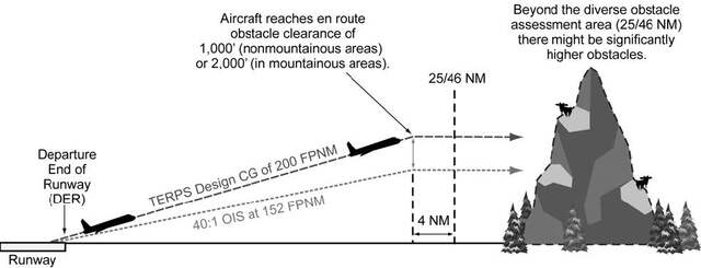
-
Takeoff Obstacles. Takeoff Obstacles Notes in the “Takeoff Minimums and (OBSTACLE) Departure Procedures” section of the Terminal Procedures Publication (TPP) identifies obstacle(s) that penetrate the 40:1 OCS. The obstacle notes alert the pilot to the height and location of the obstacles relative to the DER so they can be avoided. This can be accomplished in a variety of ways: the pilot may be able to see and avoid the obstruction; early liftoff/climb performance may allow the aircraft to cross well above the obstacle(s); or if the obstacle(s) cannot be visually acquired during departure, the takeoff should be delayed or another runway selected for the IFR departure.
-
Takeoff obstacles will be published as low, close-in and/or takeoff minimums obstacle notes.
- Low, close-in obstacles require a higher than standard climb gradient (within 1 NM or less from DER) to an altitude of 200 feet or less above DER elevation and do not require increased takeoff minimums.
- Takeoff minimums obstacles require a higher than standard climb gradient (within 2.6 NM from DER) to an altitude greater than 200 feet above the DER elevation and require increased takeoff minimums. These obstacles are published with higher than standard ceiling and visibility takeoff minimums and are published in the same obstacle listing.
- Obstacle notes are not required to be charted on SIDs. When a pilot is assigned a SID for departure refer to the airport entry in the TPP or the graphic ODP to obtain information on the takeoff obstacles.
-
The FAA redefined the initial climb area criteria that are used to evaluate and identify the obstacles that penetrate the 40:1 OCS. The takeoff obstacle notes are published in a different manner and an additional minimums option is added for the departure. To ensure the pilot knows which evaluation was accomplished, the charting will be different by bolding certain headers and runway information. Until the FAA can amend all departures the legacy obstacle notes will still be published.
- For textual departures, the headers Takeoff Minimums, Departure Procedures, and Takeoff Obstacle Notes will be bolded and underlined. The specific runway entries under each header will continue to be bolded.
- For graphic departure procedures, the headers Takeoff Minimums and Takeoff Obstacle Notes will be bolded and continue to be underlined. The specific runway entries for these headers will be bolded. In the Departure Route Description section of the graphic departure, the heading will be bolded and underlined and the runway information will just be bolded.
- Legacy takeoff obstacle notes combine low, close-in and takeoff obstacles for each runway.
- New takeoff obstacle notes separate low, close-in and takeoff minimums obstacle notes. There is also a DER crossing altitude included in the notes section, providing the pilot with a DER crossing height that clears all obstacles that penetrate the 40:1 OCS.
- The obstacles are described with an inner limit from the DER, using the word “beginning,” expressed in 1/4 SM increments rounded down and an outer limit, using the words “extending to” expressed in 1/4 SM increments rounded up. They will also be described in relation to the extended runway centerline as “left, right, or crossing.” Crossing means they are within 100ft of the centerline. Left or right means they are greater than 100 ft from centerline. Both an MSL altitude and height above DER elevation will be provided for the obstacle that penetrates the 40:1 OCS the most. This allows the pilot to determine when the reported weather conditions are adequate to see and avoid the low, close-in obstacle(s) if aircraft performance does not permit the aircraft to climb over them. It also allows the pilot to correlate the position of the obstacles and the MSL elevation and height above DER for the controlling obstacle for the published higher than standard takeoff minimums.
-
A DER crossing height using standard ceiling/visibility is provided as a new takeoff minimums option for pilots in addition to the current options (higher than standard ceiling/visibility or standard ceiling/visibility with a higher than standard climb gradient, or a reduced takeoff runway length with a standard climb gradient and standard ceiling/visibility).
EXAMPLE-
Legacy takeoff minimums and obstacle notes
TAKEOFF MINIMUMS:
Rwy12 L/R, 400-2 1/2 or std. w/min. climb of 261’ per NM to 500.
TAKEOFF OBSTACLE NOTES:
Rwy 14, trees 2011' from DER, 29' left of centerline, 100' AGL/3829' MSL.
Rwy 32, trees 1009' from DER, 697' left of centerline, 100' AGL/3839' MSL.
Tower 4448' from DER, 1036' left of centerline, 165' AGL/3886' MSL.
EXAMPLE-
New takeoff minimums and obstacle notes
TAKEOFF MINIMUMS:
Rwy12 L/R: 400-2 1/2 or std. w/min. climb of 261' per NM to 500 or standard and crossing DER 66' above DER Elev clears takeoff minimums obstacles.
TAKEOFF OBSTACLE NOTES:
Rwy 12L LOW, CLOSE-IN OBSTACLES: trees beginning 600' from DER, extending to 1/2 SM, crossing centerline, up to 156' MSL, 86' above DER, crossing DER 49' above DER Elev clears low, close-in obstacles.
Rwy 12L TAKEOFF MINIMUMS OBSTACLES: buildings, crane, tower beginning 1 1/2 SM from DER, extending to 1 3/4 SM, left, right, and crossing centerline, up to 373' MSL, 284' above DER, crossing DER at 66' above DER Elev clears takeoff minimums obstacles.
Rwy 12R LOW, CLOSE-IN OBSTACLES: obstacles 35' and below.
Rwy 12R TAKEOFF MINIMUMS OBSTACLES: buildings, crane, tower beginning 1 1/2 SM from DER, extending to 1 3/4 SM, left, right, and crossing centerline, up to 373' MSL, 284' above DER, crossing DER at 66' above DER Elev clears takeoff minimums obstacles.
Rwy 30L/R LOW, CLOSE-IN OBSTACLES: obstacles 35' and below.
- Compliance with 14 CFR part 121 or 135 one-engine-inoperative (OEI) departure performance requirements, or similar ICAO/State rules, cannot be assured by the sole use of takeoff obstacle note data as published in the TPP. Operators conducting these operations should refer to precise data sources (GIS database, etc.) specifically intended for OEI departure planning (see AC 120-91).
-
Takeoff obstacles will be published as low, close-in and/or takeoff minimums obstacle notes.
-
Climb gradients greater than 200 FPNM are specified when required to support procedure design constraints, obstacle clearance, and/or airspace restrictions. Compliance with a climb gradient for these purposes is mandatory when the procedure is part of the ATC clearance, unless increased takeoff minimums are provided and weather conditions allow compliance with these minimums.
NOTE-
Climb gradients for ATC purposes are being phased out on SIDs.
EXAMPLE-
“Cross ALPHA intersection at or below 4000; maintain 6000.” The pilot climbs at least 200 FPNM to 6000. If 4000 is reached before ALPHA, the pilot levels off at 4000 until passing ALPHA; then immediately resumes at least 200 FPNM climb.
EXAMPLE-
“TAKEOFF MINIMUMS: RWY 27, Standard with a minimum climb of 280' per NM to 2500.” A climb of at least 280 FPNM is required to 2500 and is mandatory when the departure procedure is included in the ATC clearance.
NOTE-
Some SIDs still retain labeled “ATC” climb gradients published or have climb gradients that are established to meet a published altitude restriction that is not required for obstacle clearance or procedure design criteria. These procedures will be revised in the course of the normal procedure amendment process.
-
Climb gradients may be specified only to an altitude/fix, above which the normal gradient applies. An ATC-required altitude restriction published at a fix, will not have an associated climb gradient published with that restriction. Pilots are expected to determine if crossing altitudes can be met, based on the performance capability of the aircraft they are operating.
EXAMPLE-
“Minimum climb 340 FPNM to ALPHA.” The pilot climbs at least 340 FPNM to ALPHA, then at least 200 FPNM to MIA.
-
A Visual Climb Over Airport (VCOA) procedure is a departure option for an IFR aircraft, operating in visual meteorological conditions equal to or greater than the specified visibility and ceiling, to visually conduct climbing turns over the airport to the published “at or above” altitude. At this point, the pilot may proceed in instrument meteorological conditions to the first en route fix using a diverse departure, or to proceed via a published routing to a fix from where the aircraft may join the IFR en route structure, while maintaining a climb gradient of at least 200 feet per nautical mile. VCOA procedures are developed to avoid obstacles greater than 3 statute miles from the departure end of the runway as an alternative to complying with climb gradients greater than 200 feet per nautical mile. Pilots are responsible to advise ATC as early as possible of the intent to fly the VCOA option prior to departure. Pilots are expected to remain within the distance prescribed in the published visibility minimums during the climb over the airport until reaching the “at or above” altitude for the VCOA procedure. If no additional routing is published, then the pilot may proceed in accordance with their IFR clearance. If additional routing is published after the “at-or-above” altitude, the pilot must comply with the route to a fix that may include a climb-in-holding pattern to reach the MEA/MIA for the en route portion of their IFR flight. These textual procedures are published in the Takeoff Minimums and (Obstacle) Departure Procedures section of the TPP and/or appear as an option on a Graphic ODP.
EXAMPLE-
TAKEOFF MINIMUMS: Rwy 32, standard with minimum climb of 410' per NM to 3000' or 1100-3 for VCOA.
VCOA: Rwy 32, obtain ATC approval for VCOA when requesting IFR clearance. Climb in visual conditions to cross Broken Bow Muni/Keith Glaze Field at or above 3500' before proceeding on course.
-
Unless specified otherwise, required obstacle clearance for all departures, including diverse, is based on the pilot crossing the departure end of the runway at least 35 feet above the departure end of runway elevation, climbing to 400 feet above the departure end of runway elevation before making the initial turn, and maintaining a minimum climb gradient of 200 feet per nautical mile (FPNM), unless required to level off by a crossing restriction, until the minimum IFR altitude. A greater climb gradient may be specified in the DP to clear obstacles or to achieve an ATC crossing restriction. If an initial turn higher than 400 feet above the departure end of runway elevation is specified in the DP, the turn should be commenced at the higher altitude. If a turn is specified at a fix, the turn must be made at that fix. Fixes may have minimum and/or maximum crossing altitudes that must be adhered to prior to passing the fix. In rare instances, obstacles that exist on the extended runway centerline may make an “early turn” more desirable than proceeding straight ahead. In these cases, the published departure instructions will include the language “turn left(right) as soon as practicable.” These departures will also include a ceiling and visibility minimum of at least 300 and 1. Pilots encountering one of these DPs should preplan the climb out to gain altitude and begin the turn as quickly as possible within the bounds of safe operating practices and operating limitations. This type of departure procedure is being phased out.
-
Obstacle Clearance Responsibilities. DPs are designed so that the pilot's adherence to the procedure's lateral path and vertical climb requirements will ensure obstacle protection.
- Obstacle clearance responsibility rests with the pilot when he/she chooses to depart IFR under 14 CFR part 91 and has not filed or been cleared for an ODP or an ATC-assigned SID or assigned headings for a DVA from the departure runway. Standard takeoff minimums are one statute mile for aircraft having two engines or less and one-half statute mile for aircraft having more than two engines. Higher than standard ceiling and visibility minimums will allow visual avoidance of the obstacles during the initial climb at the standard climb gradient.
-
When cleared to depart IFR using the ODP, SID, VCOA, or assigned headings for DVA, pilots must reference the published takeoff minimums and takeoff obstacle notes.
- Since the presence of low, close-in obstacles do not require publishing increased takeoff minimums the pilot should consider, if necessary to see and avoid these obstacles, the weather at time of takeoff. Based on the position of low, close-in obstacles, weather no less than 300 ft and 1 NM may be necessary to visually avoid obstacles.
- Takeoff minimums obstacles are especially critical to aircraft that do not lift off until close to the departure end of the runway or which climb at the minimum rate. When departing IFR using the higher than standard takeoff minimums option, pilots are responsible for visually avoiding takeoff minimums obstacles. Pilots should also consider drift following lift-off to ensure sufficient clearance from these obstacles. The segment of the procedure that requires the pilot to see and avoid obstacles ends when the aircraft is beyond or above the ceiling and visibility published to avoid these obstacles.
- When departing using the VCOA, obstacle avoidance is not guaranteed if the pilot maneuvers farther from the airport than the published visibility minimum for the VCOA prior to reaching the published VCOA altitude. Pilots are responsible for maintaining clearance from low, close-in obstacles.
-
When departing using a DVA, pilots are responsible for maintaining clearance from low, close-in obstacles. DVAs may also require a higher than standard climb gradient. Standard takeoff minimums apply when departing a runway under IFR when using the DVA. The existence of a DVA will be noted in the Takeoff Minimums and (Obstacle) Departure Procedure section of the TPP.
EXAMPLE-
DIVERSE VECTOR AREA (RADAR VECTORS) AMDT 1 14289 (FAA)
Rwy 6R, headings as assigned by ATC; requires minimum climb of 290' per NM to 400.
Rwys 6L, 7L, 7R, 24R, 25R, headings as assigned by ATC.
-
In all cases, continued obstacle clearance is based on having climbed a minimum of 200 feet per nautical mile to the specified point and then continuing to climb at least 200 feet per nautical mile during the departure until reaching the minimum en route altitude, unless higher than standard climb gradient is published. When a higher than standard climb gradient is published and used, that climb gradient is maintained, until reaching the climb gradient termination altitude, after which the standard 200 feet per nautical mile is maintained until reaching the minimum en route altitude.
NOTE-
As is always the case, when used by the controller during departure, the term “radar contact” should not be interpreted as relieving pilots of their responsibility to maintain appropriate terrain and obstruction clearance, which may include flying the obstacle DP.
-
Where are DPs located? DPs and DVAs will be listed by airport in the IFR Takeoff Minimums and (Obstacle) Departure Procedures Section, Section L, of the TPP. If the DP is textual, it will be described in TPP Section L. SIDs and complex ODPs will be published graphically and named. The name will be listed by airport name and runway in Section L. Graphic ODPs will also have the term “(OBSTACLE)” printed in the charted procedure title, differentiating them from SIDs.
- An ODP that has been developed solely for obstacle avoidance will be indicated with the symbol “T” on appropriate Instrument Approach Procedure (IAP) charts and DP charts for that airport. The “T” symbol will continue to refer users to TPP Section C. In the case of a graphic ODP, the TPP Section C will only contain the name of the ODP. Since there may be both a textual and a graphic DP, Section C should still be checked for additional information. The nonstandard takeoff minimums and minimum climb gradients found in TPP Section C also apply to charted DPs and radar vector departures unless different minimums are specified on the charted DP. Takeoff minimums and departure procedures apply to all runways unless otherwise specified. New graphic DPs will have all the information printed on the graphic depiction. As a general rule, ATC will only assign an ODP from a non-towered airport when compliance with the ODP is necessary for aircraft to aircraft separation. Pilots may use the ODP to help ensure separation from terrain and obstacles.
-
Responsibilities
-
Each pilot, prior to departing an airport on an IFR flight should:
- Consider the type of terrain and other obstacles on or in the vicinity of the departure airport;
- Determine whether an ODP is available;
- Determine if obstacle avoidance can be maintained visually or if the ODP should be flown; and
-
Consider the effect of degraded climb performance and the actions to take in the event of an engine loss during the departure. Pilots should notify ATC as soon as possible of reduced climb capability in that circumstance.
NOTE-
Guidance concerning contingency procedures that address an engine failure on takeoff after V1 speed on a large or turbine-powered transport category airplane may be found in AC 120-91, Airport Obstacle Analysis.
- Determine if a DVA is published and whether the aircraft is capable of meeting the published climb gradient. Advise ATC when requesting the IFR clearance, or as soon as possible, if unable to meet the DVA climb gradient.
- Check for Takeoff Obstacle Notes published in the TPP for the takeoff runway.
- Pilots should not exceed a published speed restriction associated with a SID waypoint until passing that waypoint.
- After an aircraft is established on a SID and subsequently vectored or cleared to deviate off of the SID or SID transition, pilots must consider the SID canceled, unless the controller adds “expect to resume SID;” pilots should then be prepared to rejoin the SID at a subsequent fix or procedure leg. If the SID contains published altitude and/or speed restrictions, those restrictions are canceled and pilots will receive an altitude to maintain and, if necessary, a speed. ATC may also interrupt the vertical navigation of a SID and provide alternate altitude instructions while the aircraft remains established on the published lateral path. Aircraft may be vectored off of an ODP, or issued an altitude lower than a published altitude on an ODP, at which time the ODP is canceled. In these cases, ATC assumes responsibility for terrain and obstacle clearance. In all cases, the minimum 200 FPNM climb gradient is assumed.
- Aircraft instructed to resume a SID procedure such as a DP or SID which contains speed and/or altitude restrictions, must be:
- A clearance for a SID which does not contain published crossing restrictions, and/or is a SID with a Radar Vector segment or a Radar Vector SID, will be issued using the phraseology “Maintain (altitude).”
-
A clearance for a SID which contains published altitude restrictions may be issued using the phraseology “climb via.” Climb via is an abbreviated clearance that requires compliance with the procedure lateral path, associated speed and altitude restrictions along the cleared route or procedure. Clearance to “climb via” authorizes the pilot to:
- When used in the IFR departure clearance, in a PDC, DCL or whencleared to a waypoint depicted on a SID, to join the procedure after departure or to resume the procedure.
- When vertical navigation is interrupted and an altitude is assigned to maintain which is not contained on the published procedure, to climb from that previously-assigned altitude at pilot's discretion to the altitude depicted for the next waypoint.
-
Once established on the depicted departure, to navigate laterally and climb to meet all published or assigned altitude and speed restrictions.
NOTE-
- When otherwise cleared along a route or procedure that contains published speed restrictions, the pilot must comply with those speed restrictions independent of a climb via clearance.
- ATC anticipates pilots will begin adjusting speed the minimum distance necessary prior to a published speed restriction so as to cross the waypoint/fix at the published speed. Once at the published speed ATC expects pilots will maintain the published speed until additional adjustment is required to comply with further published or ATC assigned speed restrictions or as required to ensure compliance with 14 CFR section 91.117.
- If ATC interrupts lateral/vertical navigation while an aircraft is flying a SID, ATC must ensure obstacle clearance. When issuing a “climb via” clearance to join or resume a procedure ATC must ensure obstacle clearance until the aircraft is established on the lateral and vertical path of the SID.
- ATC will assign an altitude to cross if no altitude is depicted at a waypoint/fix or when otherwise necessary/ required, for an aircraft on a direct route to a waypoint/fix where the SID will be joined or resumed.
- SIDs will have a “top altitude;” the “top altitude” is the charted “maintain” altitude contained in the procedure description or assigned by ATC.
REFERENCE-
FAA Order JO 7110.65, Para 5-6-2, Methods.PCG, Climb Via, Top Altitude.
EXAMPLE-
- Lateral route clearance:
“Cleared Loop Six departure.”
NOTE-
The aircraft must comply with the SID lateral path, and any published speed restrictions.
- Routing with assigned altitude:
“Cleared Loop Six departure, climb and maintain four thousand.”
NOTE-
The aircraft must comply with the SID lateral path, and any published speed restriction while climbing unrestricted to four thousand.
- (A pilot filed a flight plan to the Johnston Airport using the Scott One departure, Jonez transition, then Q-145. The pilot filed for FL350. The Scott One includes altitude restrictions, a top altitude and instructions to expect the filed altitude ten minutes after departure). Before departure ATC uses PDC, DCL or clearance delivery to issue the clearance:“Cleared to Johnston Airport, Scott One departure, Jonez transition, Q-OneForty-five. Climb via SID.”
NOTE-
In Example 3, the aircraft must comply with the Scott One departure lateral path and any published speed and altitude restrictions while climbing to the SID top altitude.
- (Using the Example 3 flight plan, ATC determines the top altitude must be changed to FL180). The clearance will read:
“Cleared to Johnston Airport, Scott One departure, Jonez transition, Q-One Forty-five, Climb via SID except maintain flight level one eight zero.”
NOTE-
In Example 4, the aircraft must comply with the Scott One departure lateral path and any published speed and altitude restrictions while climbing to FL180. The aircraft must stop climb at FL180 until issued further clearance by ATC.
- (An aircraft was issued the Suzan Two departure, “climb via SID” in the IFR departure clearance. After departure ATC must change a waypoint crossing restriction). The clearance will be:“Climb via SID except cross Mkala at or above seven thousand.”
NOTE-
In Example 5, the aircraft will comply with the Suzan Two departure lateral path and any published speed and altitude restrictions and climb so as to cross Mkala at or above 7,000; remainder of the departure must be flown as published.
- (An aircraft was issued the Teddd One departure, “climb via SID” in the IFR departure clearance. An interim altitude of 10,000 was issued instead of the published top altitude of FL 230). After departure ATC is able to issue the published top altitude. The clearance will be:
“Climb via SID.”
NOTE-
In Example 6, the aircraft will track laterally and vertically on the Teddd One departure and initially climb to 10,000; Once re-issued the “climb via” clearance the interim altitude is canceled aircraft will continue climb to FL230 while complying with published restrictions.
- (An aircraft was issued the Bbear Two departure, “climb via SID” in the IFR departure clearance. An interim altitude of 16,000 was issued instead of the published top altitude of FL 190). After departure, ATC is able to issue a top altitude of FL300 and still requires compliance with the published SID restrictions. The clearance will be: “Climb via SID except maintain flight level three zero zero.”
NOTE-
In Example 7, the aircraft will track laterally and vertically on the Bbear Two departure and initially climb to 16,000; Once re-issued the “climb via” clearance the interim altitude is canceled and the aircraft will continue climb to FL300 while complying with published restrictions.
- (An aircraft was issued the Bizee Two departure, “climb via SID.” After departure, ATC vectors the aircraft off of the SID, and then issues a direct routing to rejoin the SID at Rockr waypoint which does not have a published altitude restriction. ATC wants the aircraft to cross at or above 10,000). The clearance will read:“Proceed direct Rockr, cross Rockr at or above one-zero thousand, climb via the Bizee Two departure.”
NOTE-
In Example 8, the aircraft will join the Bizee Two SID at Rockr at or above 10,000 and then comply with the published lateral path and any published speed or altitude restrictions while climbing to the SID top altitude.
- (An aircraft was issued the Suzan Two departure, “climb via SID” in the IFR departure clearance. After departure ATC vectors the aircraft off of the SID, and then clears the aircraft to rejoin the SID at Dvine waypoint, which has a published crossing restriction). The clearance will read:
“Proceed direct Dvine, Climb via the Suzan Two departure.”
NOTE-
In Example 9, the aircraft will join the Suzan Two departure at Dvine, at the published altitude, and then comply with the published lateral path and any published speed or altitude restrictions.
-
Pilots cleared for vertical navigation using the phraseology “climb via” must inform ATC, upon initial contact, of the altitude leaving and any assigned restrictions not published on the procedure.
EXAMPLE-
- (Cactus 711 is cleared to climb via the Laura Two departure. The Laura Two has a top altitude of FL190):
“Cactus Seven Eleven leaving two thousand, climbing via the Laura Two departure.” - (Cactus 711 is cleared to climb via the Laura Two departure, but ATC changed the top altitude to16,000):
“Cactus Seven Eleven leaving two thousand for one-six thousand, climbing via the Laura Two departure.”
- (Cactus 711 is cleared to climb via the Laura Two departure. The Laura Two has a top altitude of FL190):
-
If prior to or after takeoff an altitude restriction is issued by ATC, all previously issued “ATC" altitude restrictions are canceled including those published on a SID. Pilots must still comply with all speed restrictions and lateral path requirements published on the SID unless canceled by ATC.
EXAMPLE-
Prior to takeoff or after departure ATC issues an altitude change clearance to an aircraft cleared to climb via a SID but ATC no longer requires compliance with published altitude restrictions:“Climb and maintain flight level two four zero.”
NOTE-
The published SID altitude restrictions are canceled; The aircraft should comply with the SID lateral path and begin an unrestricted climb to FL240. Compliance with published speed restrictions is still required unless specifically deleted by ATC.
- Altitude restrictions published on an ODP are necessary for obstacle clearance and/or design constraints. Crossing altitudes and speed restrictions on ODPs cannot be canceled or amended by ATC.
-
Each pilot, prior to departing an airport on an IFR flight should:
-
PBN Departure Procedures
- All public PBN SIDs and graphic ODPs are normally designed using RNAV 1, RNP 1, or A-RNP NavSpecs. These procedures generally start with an initial track or heading leg near the departure end of runway (DER). In addition, these procedures require system performance currently met by GPS or DME/DME/IRU PBN systems that satisfy the criteria discussed in the latest AC 90-100, U.S. Terminal and En Route Area Navigation (RNAV) Operations. RNAV 1 and RNP 1 procedures must maintain a total system error of not more than 1 NM for 95 percent of the total flight time. Minimum values for A-RNP procedures will be charted in the PBN box (for example, 1.00 or 0.30).
- In the U.S., a specific procedure's PBN requirements will be prominently displayed in separate, standardized notes boxes. For procedures with PBN elements, the “PBN box” will contain the procedure's NavSpec(s); and, if required: specific sensors or infrastructure needed for the navigation solution, any additional or advanced functional requirements, the minimum RNP value, and any amplifying remarks. Items listed in this PBN box are REQUIRED for the procedure's PBN elements.
Section 3. En Route Procedures
-
ARTCC Communications
-
Direct Communications, Controllers and Pilots.
- ARTCCs are capable of direct communications with IFR air traffic on certain frequencies. Maximum communications coverage is possible through the use of Remote Center Air/Ground (RCAG) sites comprised of both VHF and UHF transmitters and receivers. These sites are located throughout the U.S. Although they may be several hundred miles away from the ARTCC, they are remoted to the various ARTCCs by land lines or microwave links. Since IFR operations are expedited through the use of direct communications, pilots are requested to use these frequencies strictly for communications pertinent to the control of IFR aircraft. Flight plan filing, en route weather, weather forecasts, and similar data should be requested through FSSs, company radio, or appropriate military facilities capable of performing these services.
- An ARTCC is divided into sectors. Each sector is handled by one or a team of controllers and has its own sector discrete frequency. As a flight progresses from one sector to another, the pilot is requested to change to the appropriate sector discrete frequency.
-
Controller Pilot Data Link Communications (CPDLC) is a system that supplements air/ground voice communications. The CPDLC's principal operating criteria are:
- Voice remains the primary and controlling air/ground communications means.
- Participating aircraft will need to have the appropriate CPDLC avionics equipment in order to receive uplink or transmit downlink messages.
-
En Route CPDLC Initial Services offer the following services: Altimeter Setting (AS), Transfer of Communications (TOC), Initial Contact (IC), and limited route assignments, including airborne reroutes (ABRR), limited altitude assignments, and emergency messages.
-
Altimeter settings will be uplinked automatically when appropriate after a Monitor TOC. Altimeter settings will also be uplinked automatically when an aircraft receives an uplinked altitude assignment below FL 180. A controller may also manually send an altimeter setting message.
NOTE-
When conducting instrument approach procedures, pilots are responsible to obtain and use the appropriate altimeter setting in accordance with 14 CFR section 97.20. CPDLC issued altimeter settings are excluded for this purpose.
- Initial contact is a safety validation transaction that compares a pilot's initiated altitude downlink message with an aircraft's stored altitude in the ATC automation system. When an IC mismatch or Confirm Assigned Altitude (CAA) downlink time-out indicator is displayed in the Full Data Block (FDB) and Aircraft List (ACL), the controller who has track control of the aircraft must use voice communication to verify the assigned altitude of the aircraft, and acknowledge the IC mismatch/time-out indicator.
- Transfer of communications automatically establishes data link contact with a succeeding sector.
- Menu text transmissions are scripted nontrajectory altering uplink messages.
-
The CPDLC Message Elements for the Initial Capabilities rollout are contained in TBL 5-3-1 through TBL 5-3-19, CPDLC Message Elements, below.
NOTE-
The FAA is not implementing ATN B1; the ATN B1 column in the tables is there for informational purposes only
TBL 5-3-1
Route Uplink Message Elements (RTEU)CPDLC Message Sets
Operational Definition in PANS-ATM (Doc 4444)
FANS 1/A
ATN B1
Response
Message Element Identifier
Message Element Intended Use
Format for Message Element Display
UM74 PROCEED DIRECT TO (position)
UM74 PROCEED DIRECT TO (position)
W/U
RTEU-2
Instruction to proceed directly to the specified position.
PROCEED DIRECT TO (position)
UM79 CLEARED TO (position) via (route clearance)
UM79 CLEARED TO (position) via (route clearance)
W/U
RTEU-6
Instruction to proceed to the specified position via the specified route.
CLEARED TO (position) VIA (departure data[O]) (en-route data)
UM80 CLEARED (route clearance)
UM80 CLEARED (route clearance)
W/U
RTEU-7
Instruction to proceed via the specified route.
CLEARED (departure data[O]) (en-route data) (arrival approach data)
UM83 AT (position) CLEARED (route clearance)
N/A
W/U
RTEU-9
Instruction to proceed from the specified position via the specified route.
AT (position) CLEARED (en-route data) (arrival approach data)
TBL 5-3-2
Route Downlink Message Elements (RTED)CPDLC Message Sets
Operational Definition in PANS-ATM (Doc 4444)
FANS 1/A
ATN B1
Response
Message Element Identifier
Message Element Intended Use
Format for Message Element Display
DM22 REQUEST DIRECT TO (position)
DM22 REQUEST DIRECT TO (position)
Y
RTED-1
Request for a direct clearance to the specified position.
REQUEST DIRECT TO (position)
TBL 5-3-3
Lateral Downlink Message Elements (LATD)CPDLC Message Sets
Operational Definition in PANS-ATM (Doc 4444)
FANS 1/A
ATN B1
Response
Message Element Identifier
Message Element Intended Use
Format for Message Element Display
DM59 DIVERTING TO (position) VIA (route clearance)
Note 1. - H alert attribute
Note 2. - N
response attributeN/A
N1
LATD-5
Report indicating diverting to the specified position via the specified route, which may be sent without any previous coordination done with ATC.
DIVERTING TO (position) VIA (en-route data) (arrival approach data[O])
DM60
OFFSETTING (distance offset) (direction) OF ROUTE
Note 1. - H alert attribute
Note 2. - N
response attributeN/A
N1
LATD-6
Report indicating that the aircraft is offsetting to a parallel track at the specified distance in the specified direction off from the cleared route.
OFFSETTING (specified distance) (direction) OF ROUTE
DM80 DEVIATING (deviation offset) (direction) OF ROUTE
Note 1. - H alert attribute
Note 2. - N response attributeN/A
N1
LATD-7
Report indicating deviating specified distance or degrees in the specified direction from the cleared route.
DEVIATING (specifiedDeviation) (direction) OF ROUTE
1 ICAO Document 10037, Global Operational Data Link (GOLD) Manual has these values set to Y in their table.
TBL 5-3-4
Level Uplink Message Elements (LVLU)CPDLC Message Sets
Operational Definition in PANS-ATM (Doc 4444)
FANS 1/A
ATN B1
Response
Message Element Identifier
Message Element Intended Use
Format for Message Element Display
UM19 MAINTAIN (altitude)
Note - Used for a single levelUM19 MAINTAIN (level)
W/U
LVLU-5
Instruction to maintain the specified level or vertical range.
MAINTAIN (level)
UM20 CLIMB TO AND MAINTAIN
(altitude)
Note - Used for a single levelUM20 CLIMB TO (level)
W/U
LVLU-6
Instruction that a climb to the specified level or vertical range is to commence and once reached is to be maintained.
CLIMB TO (level)
UM23 DESCEND TO AND MAINTAIN (altitude)
Note - Used for a single levelUM23 DESCEND TO (level)
W/U
LVLU-9
Instruction that a descent to the specified level or vertical range is to commence and once reached is to be maintained.
DESCEND TO (level)
UM36 EXPEDITE CLIMB TO (altitude)
Note - This message element is equivalent to SUPU-3 plus LVLU-6 in Doc 4444.N/A
W/U
LVLU-6
Instruction that a climb to the specified level or vertical range is to commence and once reached is to be maintained.
CLIMB TO (level)
UM37 EXPEDITE DESCEND TO (altitude)
N/A
W/U
LVLU-9
Instruction that a descent to the specified level or vertical range is to commence and once reached is to be maintained.
DESCEND TO (level)
UM38 IMMEDIATELY CLIMB TO (altitude)
Note - This message element is equivalent to EMGU-2 plus LVLU-6 in Doc 4444.N/A
W/U
LVLU-6
Instruction that a climb to the specified level or vertical range is to commence and once reached is to be maintained.
CLIMB TO (level)
UM39 IMMEDIATELY DESCEND TO (altitude)
Note - This message element is equivalent to EMGU-2 plus LVLU-9 in Doc 4444.N/A
W/U
LVLU-9
Instruction that a descent to the specified level or vertical range is to commence and once reached is to be maintained.
DESCEND TO (level)
UM135 CONFIRM ASSIGNED ALTITUDE
Note - NE response attributeN/A
Y
LVLU-27
Request to confirm the assigned level.
CONFIRM ASSIGNED LEVEL
UM177 AT PILOTS DISCRETION
N/A
NE
See Note
Request to confirm the assigned level.
NOTE-
ICAO Document 10037, Global Operational Data Link (GOLD) Manual does not include this in its tables.
TBL 5-3-5
Level Downlink Message Elements (LVLD)CPDLC Message Sets
Operational Definition in PANS-ATM (Doc 4444)
FANS 1/A
ATN B1
Response
Message Element Identifier
Message Element Intended Use
Format for Message Element Display
DM6 REQUEST (altitude)
Note - Used for a single levelDM6 REQUEST (level)
Y
LVLD-1
Request to fly at the specified level or vertical range.
REQUEST (level)
DM9 REQUEST CLIMB TO (altitude)
DM9 REQUEST CLIMB TO (level)
Y
LVLD-2
Request for a climb to the specified level or vertical range.
REQUEST CLIMB TO (level)
DM10 REQUEST DESCENT TO (altitude)
DM10 REQUEST DESCENT TO (level)
Y
LVLD-3
Request for a descent to the specified level or vertical range.
REQUEST DESCENT TO (level)
DM38 ASSIGNED LEVEL (altitude)
Note - Used for a single levelDM38 ASSIGNED LEVEL (level)
N
LVLD-11
Confirmation that the assigned level or vertical range is the specified level or vertical range.
ASSIGNED LEVEL (level)
DM61 DESCENDING TO (altitude)
Note - urgent alert attributeN/A
N
LVLD-14
Report indicating descending to the specified level.
DESCENDING TO (level single)
TBL 5-3-6
Crossing Constraint Message Elements (CSTU)CPDLC Message Sets
Operational Definition in PANS-ATM (Doc 4444)
FANS 1/A
ATN B1
Response
Message Element Identifier
Message Element Intended Use
Format for Message Element Display
UM49 CROSS (position) AT AND MAINTAIN (altitude)
Note 1. - A vertical range cannot be provided.
Note 2. - This message element is equivalent to CSTU-1 plus LVLU-5 in Doc 4444.N/A
W/U
CSTU-1
Instruction that the specified position is to be crossed at the specified level or within the specified vertical range.
CROSS (position) AT (level)
UM61 CROSS (position) AT AND MAINTAIN (altitude) AT (speed)
Note 1. - A vertical range cannot be provided.
Note 2. - This message element is equivalent to CSTU-14 plus LVLU-5 in Doc 4444.UM61 CROSS (position) AT AND MAINTAIN (level) AT (speed)
W/U
CSTU-14
Instruction that the specified position is to be crossed at the level or within the vertical range, as specified, and at the specified speed.
CROSS (position) AT (level) AT (speed)
TBL 5-3-7
Air Traffic Advisory Uplink Message ElementsCPDLC Message Sets
Operational Definition in PANS-ATM (Doc 4444)
FANS 1/A
ATN B1
Response
Message Element Identifier
Message Element Intended Use
Format for Message Element Display
UM154 RADAR SERVICES TERMINATED
N/A
R
ADVU-2
Advisory that the ATS surveillance service is terminated.
SURVEILLANCE SERVICE TERMINATED
TBL 5-3-8
Voice Communications Uplink Message Elements (COMU)CPDLC Message Sets
Operational Definition in PANS-ATM (Doc 4444)
FANS 1/A
ATN B1
Response
Message Element Identifier
Message Element Intended Use
Format for Message Element Display
UM117 CONTACT (ICAO unit name) (frequency)
UM117 CONTACT (unit name) (frequency)
W/U
COMU-1
Instruction to establish voice contact with the specified ATS unit on the specified frequency.
CONTACT (unit name) (frequency)
UM120 MONITOR (ICAO unit name) (frequency)
UM120 MONITOR (unit name) (frequency)
W/U
COMU-5
Instruction to monitor the specified ATS unit on the specified frequency. The flight crew is not required to establish voice contact on the frequency.
MONITOR (unit name) (frequency)
TBL 5-3-9
Voice Communications Downlink Message Elements (COMD)CPDLC Message Sets
Operational Definition in PANS-ATM (Doc 4444)
FANS 1/A
ATN B1
Response
Message Element Identifier
Message Element Intended Use
Format for Message Element Display
DM20 REQUEST VOICE CONTACT
Note - Used when a frequency is not required.N/A
Y
COMD-1
Request for voice contact on the specified frequency.
REQUEST VOICE CONTACT (frequency)
TBL 5-3-10
Emergency/Urgency Uplink Message Elements (EMGU)CPDLC Message Sets
Operational Definition in PANS-ATM (Doc 4444)
FANS 1/A
ATN B1
Response
Message Element Identifier
Message Element Intended Use
Format for Message Element Display
Used in combination with LVLU-6 and LVLU-9, which is implemented in
FANS 1/A as:
UM38 IMMEDIATELY CLIMB TO (altitude)
UM39 IMMEDIATELY DESCEND TO (altitude)N/A
N
EMGU-2
Instruction to immediately comply with the associated instruction to avoid imminent situation.
Immediately
TBL 5-3-11
Emergency/Urgency Downlink Message Elements (EMGD)CPDLC Message Sets
Operational Definition in PANS-ATM (Doc 4444)
FANS 1/A
ATN B1
Response
Message Element Identifier
Message Element Intended Use
Format for Message Element Display
DM55 PAN PAN PAN Note - N response attribute
N/A
Y
EMGD-1
Indication of an urgent situation.
PAN PAN PAN
DM56 MAYDAY MAYDAY MAYDAY
Note - N response attributeN/A
Y
EMGD-2
Indication of an emergency situation.
MAYDAY
MAYDAY
MAYDAYDM57 (remaining fuel) OF FUEL REMAINING AND (remaining souls) SOULS ON BOARD
Note - N response attributeN/A
Y
EMGD-3
Report indicating fuel remaining (time) and number of persons on board.
(remaining fuel) ENDURANCE AND (persons on board) PERSONS ON BOARD
DM58 CANCEL EMERGENCY
Note - N response attributeN/A
Y
EMGD-4
Indication that the emergency situation is canceled.
CANCEL EMERGENCY
TBL 5-3-12
Standard Response Uplink Message Elements (RSPU)CPDLC Message Sets
Operational Definition in PANS-ATM (Doc 4444)
FANS 1/A
ATN B1
Response
Message Element Identifier
Message Element Intended Use
Format for Message Element Display
UM0 UNABLE
UM0 UNABLE
N
RSPU-1
Indication that the message cannot be complied with.
UNABLE
UM1 STANDBY
UM1 STANDBY
N
RSPU-2
Indication that the message will be responded to shortly.
STANDBY
UM3 ROGER
UM3 ROGER
N
RSPU-4
Indication that the message is received.
ROGER
TBL 5-3-13
Standard Response Downlink Message Elements (RSPD)CPDLC Message Sets
Operational Definition in PANS-ATM (Doc 4444)
FANS 1/A
ATN B1
Response
Message Element Identifier
Message Element Intended Use
Format for Message Element Display
DM0 WILCO
DM0 WILCO
N
RSPD-1
Indication that the instruction is understood and will be complied with.
WILCO
DM1 UNABLE
DM1 UNABLE
N
RSPD-2
Indication that the message cannot be complied with.
UNABLE
DM2 STANDBY
DM2 STANDBY
N
RSPD-3
Indication that the message will be responded to shortly.
STANDBY
DM3 ROGER
Note - ROGER is the only correct response to an uplink free text message.DM3 ROGER
N
RSPD-4
Indication that the message is received.
ROGER
TBL 5-3-14
Supplemental Uplink Message Elements (SUPU)CPDLC Message Sets
Operational Definition in PANS-ATM (Doc 4444)
FANS 1/A
ATN B1
Response
Message Element Identifier
Message Element Intended Use
Format for Message Element Display
UM166 DUE TO TRAFFIC
N/A
N
SUPU-2
Indication that the associated message is issued due to the specified reason.
DUE TO (specified reason uplink)
UM167 DUE TO AIRSPACE RESTRICTION
TBL 5-3-15
Supplemental Downlink Message Elements (SUPD)CPDLC Message Sets
Operational Definition in PANS-ATM (Doc 4444)
FANS 1/A
ATN B1
Response
Message Element Identifier
Message Element Intended Use
Format for Message Element Display
DM65 DUE TO WEATHER
DM65 DUE TO WEATHER
N
SUPD-1
Indication that the associated message is issued due to the specified reason.
DUE TO (specified reason downlink)
DM66 DUE TO AIRCRAFT PERFORMANCE
DM66 DUE TO AIRCRAFT PERFORMANCE
TBL 5-3-16
Free Text Uplink Message Elements (TXTU)CPDLC Message Sets
Operational Definition in PANS-ATM (Doc 4444)
FANS 1/A
ATN B1
Response
Message Element Identifier
Message Element Intended Use
Format for Message Element Display
UM169 (free text)
UM203 (free text)
R
TXTU-1
(free text)
Note-M alert attribute.
UM169 (free text) CPDLC NOT IN USE UNTIL FURTHER NOTIFICATION
N/A
R
See Note
(free text)
UM169 (free text)
“[facility designation]”
LOCAL ALTIMETER (for Altimeter Reporting Station)N/A
R
See Note
(free text)
UM169 (free text)
“[facility designation] LOCAL ALTIMETER MORE THAN ONE HOUR” OLDN/A
R
See Note
(free text)
UM169 (free text)
DUE TO WEATHERN/A
R
See Note
(free text)
UM169 (free text)
REST OF ROUTE UNCHANGEDN/A
R
See Note
(free text)
UM169 (free text)
TRAFFIC FLOW MANAGEMENT REROUTEN/A
R
See Note
(free text)
NOTE-
These are FAA scripted free text messages with no GOLD equivalent.
TBL 5-3-17
Free Text Downlink Message Elements (TXTD)CPDLC Message Sets
Operational Definition in PANS-ATM (Doc 4444)
FANS 1/A
ATN B1
Response
Message Element Identifier
Message Element Intended Use
Format for Message Element Display
DM68 (free text)
Note 1. - Urgency or Distress Alr (M)
Note 2. - Selecting any of the emergency message elements will result in this message element being enabled for the flight crew to include in the emergency message at their discretion.N/A
Y
TXTD-1
(free text)
Note - M alert attribute.TBL 5-3-18
System Management Uplink Message Elements (SYSU)CPDLC Message Sets
Operational Definition in PANS-ATM (Doc 4444)
FANS 1/A
ATN B1
Response
Message Element Identifier
Message Element Intended Use
Format for Message Element Display
UM159 ERROR (error information)
UM159 ERROR (error information)
N
SYSU-1
System-generated notification of an error.
ERROR (error information)
UM160 NEXT DATA AUTHORITY (ICAO facility designation)
Note - The facility designation is required.UM160 NEXT DATA AUTHORITY (facility)
Note - Facility parameter can specify a facility designation or no facility.N
SYSU-2
System-generated notification of the next data authority or the cancellation thereof.
NEXT DATA AUTHORITY (facility designation [O])
TBL 5-3-19
System Management Downlink Message Elements (SYSD)CPDLC Message Sets
Operational Definition in PANS-ATM (Doc 4444)
FANS 1/A
ATN B1
Response
Message Element Identifier
Message Element Intended Use
Format for Message Element Display
DM62 ERROR (error information)
DM62 ERROR (error information)
N
SYSD-1
System-generated notification of an error.
SYSD-1
DM63 NOT CURRENT DATA AUTHORITY
DM63 NOT CURRENT DATA AUTHORITY
N
SYSD-3
System-generated rejection of any CPDLC message sent from a ground facility that is not the current data authority.
SYSD-3
DM64 (ICAO facility designation)
Note - Use by FANS 1/A aircraft in B1 environments.DM107 NOT AUTHORIZED NEXT DATA AUTHORITY
Note - CDA and NDA cannot be provided.N
SYSD-5
System-generated notification that the ground system is not designated as the next data authority (NDA), indicating the identity of the current data authority (CDA). Identity of the NDA, if any, is also reported.
SYSD-5
-
Altimeter settings will be uplinked automatically when appropriate after a Monitor TOC. Altimeter settings will also be uplinked automatically when an aircraft receives an uplinked altitude assignment below FL 180. A controller may also manually send an altimeter setting message.
-
ATC Frequency Change Procedures.
-
The following phraseology will be used by controllers to effect a frequency change:
EXAMPLE-
(Aircraft identification) contact (facility name or location name and terminal function) (frequency) at (time, fix, or altitude).
NOTE-
Pilots are expected to maintain a listening watch on the transferring controller's frequency until the time, fix, or altitude specified. ATC will omit frequency change restrictions whenever pilot compliance is expected upon receipt.
-
The following phraseology should be utilized by pilots for establishing contact with the designated facility:
-
When operating in a radar environment: On initial contact, the pilot should inform the controller of the aircraft's assigned altitude preceded by the words “level,” or “climbing to,” or “descending to,” as appropriate; and the aircraft's present vacating altitude, if applicable.
EXAMPLE-
- (Name) CENTER, (aircraft identification), LEVEL (altitude or flight level).
- (Name) CENTER, (aircraft identification), LEAVING (exact altitude or flight level), CLIMBING TO OR DESCENDING TO (altitude of flight level).
NOTE-
Exact altitude or flight level means to the nearest 100 foot increment. Exact altitude or flight level reports on initial contact provide ATC with information required prior to using Mode C altitude information for separation purposes.
-
When operating in a nonradar environment:
-
On initial contact, the pilot should inform the controller of the aircraft's present position, altitude and time estimate for the next reporting point.
EXAMPLE-
(Name) CENTER, (aircraft identification), (position), (altitude), ESTIMATING (reporting point) AT (time).
-
After initial contact, when a position report will be made, the pilot should give the controller a complete position report.
EXAMPLE-
(Name) CENTER, (aircraft identification), (position), (time), (altitude), (type of flight plan), (ETA and name of next reporting point), (the name of the next succeeding reporting point), AND (remarks).
REFERENCE-
AIM, Para 5-3-2, Position Reporting.
-
On initial contact, the pilot should inform the controller of the aircraft's present position, altitude and time estimate for the next reporting point.
-
When operating in a radar environment: On initial contact, the pilot should inform the controller of the aircraft's assigned altitude preceded by the words “level,” or “climbing to,” or “descending to,” as appropriate; and the aircraft's present vacating altitude, if applicable.
-
At times controllers will ask pilots to verify that they are at a particular altitude. The phraseology used will be: “VERIFY AT (altitude).” In climbing or descending situations, controllers may ask pilots to “VERIFY ASSIGNED ALTITUDE AS (altitude).” Pilots should confirm that they are at the altitude stated by the controller or that the assigned altitude is correct as stated. If this is not the case, they should inform the controller of the actual altitude being maintained or the different assigned altitude.
CAUTION-
Pilots should not take action to change their actual altitude or different assigned altitude to the altitude stated in the controllers verification request unless the controller specifically authorizes a change.
-
The following phraseology will be used by controllers to effect a frequency change:
-
ARTCC Radio Frequency Outage. ARTCCs normally have at least one back‐up radio receiver and transmitter system for each frequency, which can usually be placed into service quickly with little or no disruption of ATC service. Occasionally, technical problems may cause a delay but switchover seldom takes more than 60 seconds. When it appears that the outage will not be quickly remedied, the ARTCC will usually request a nearby aircraft, if there is one, to switch to the affected frequency to broadcast communications instructions. It is important, therefore, that the pilot wait at least 1 minute before deciding that the ARTCC has actually experienced a radio frequency failure. When such an outage does occur, the pilot should, if workload and equipment capability permit, maintain a listening watch on the affected frequency while attempting to comply with the following recommended communications procedures:
- If two‐way communications cannot be established with the ARTCC after changing frequencies, a pilot should attempt to recontact the transferring controller for the assignment of an alternative frequency or other instructions.
-
When an ARTCC radio frequency failure occurs after two‐way communications have been established, the pilot should attempt to reestablish contact with the center on any other known ARTCC frequency, preferably that of the next responsible sector when practicable, and ask for instructions. However, when the next normal frequency change along the route is known to involve another ATC facility, the pilot should contact that facility, if feasible, for instructions. If communications cannot be reestablished by either method, the pilot is expected to request communications instructions from the FSS appropriate to the route of flight.
NOTE-
The exchange of information between an aircraft and an ARTCC through an FSS is quicker than relay via company radio because the FSS has direct interphone lines to the responsible ARTCC sector. Accordingly, when circumstances dictate a choice between the two, during an ARTCC frequency outage, relay via FSS radio is recommended.
- Oakland Oceanic FIR. The use of CPDLC and ADS-C in the Oakland Oceanic FIR (KZAK) is only permitted by Inmarsat and Iridium customers. All other forms of data link connectivity are not authorized. Users must ensure that the proper data link code is filed in Item 10a of the ICAO FPL in order to indicate which satellite medium(s) the aircraft is equipped with. The identifier for Inmarsat is J5 and the identifier for Iridium is J7. If J5 or J7 is not included in the ICAO FPL, then the LOGON will be rejected by KZAK and the aircraft will not be able to connect.
- New York Oceanic FIR. The use of CPDLC and ADS-C in the New York Oceanic FIR (KZWY) is only permitted by Inmarsat and Iridium customers. All other forms of data link connectivity are not authorized. Users must ensure that the proper data link code is filed in Item 10a of the ICAO FPL in order to indicate which satellite medium(s) the aircraft is equipped with. The identifier for Inmarsat is J5 and the identifier for Iridium is J7. If J5 or J7 is not included in the ICAO FPL, then the LOGON will be rejected by KZWY and the aircraft will not be able to connect.
-
Direct Communications, Controllers and Pilots.
-
Position Reporting
The safety and effectiveness of traffic control depends to a large extent on accurate position reporting. In order to provide the proper separation and expedite aircraft movements, ATC must be able to make accurate estimates of the progress of every aircraft operating on an IFR flight plan.
-
Position Identification.
- When a position report is to be made passing a VOR radio facility, the time reported should be the time at which the first complete reversal of the “to/from” indicator is accomplished.
- When a position report is made passing a facility by means of an airborne ADF, the time reported should be the time at which the indicator makes a complete reversal.
- When an aural or a light panel indication is used to determine the time passing a reporting point, such as a fan marker, Z marker, cone of silence or intersection of range courses, the time should be noted when the signal is first received and again when it ceases. The mean of these two times should then be taken as the actual time over the fix.
- If a position is given with respect to distance and direction from a reporting point, the distance and direction should be computed as accurately as possible.
- Except for terminal area transition purposes, position reports or navigation with reference to aids not established for use in the structure in which flight is being conducted will not normally be required by ATC.
-
Position Reporting Points. CFRs require pilots to maintain a listening watch on the appropriate frequency and, unless operating under the provisions of subparagraph c, to furnish position reports passing certain reporting points. Reporting points are indicated by symbols on en route charts. The designated compulsory reporting point symbol is a solid triangle
 and the “on request” reporting point symbol is the open triangle
  . Reports passing an “on request” reporting point are only necessary when requested by ATC.
-
Position Reporting Requirements.
- Flights Along Airways or Routes. A position report is required by all flights regardless of altitude, including those operating in accordance with an ATC clearance specifying “VFR-on-top,” over each designated compulsory reporting point along the route being flown.
- Flights Along a Direct Route. Regardless of the altitude or flight level being flown, including flights operating in accordance with an ATC clearance specifying “VFR-on-top,” pilots must report over each reporting point used in the flight plan to define the route of flight.
- Flights in a Radar Environment. When informed by ATC that their aircraft are in “Radar Contact,” pilots should discontinue position reports over designated reporting points. They should resume normal position reporting when ATC advises “RADAR CONTACT LOST” or “RADAR SERVICE TERMINATED.”
-
Flights in an Oceanic (Nonradar) Environment. Pilots must report over each point used in the flight plan to define the route of flight, even if the point is depicted on aeronautical charts as an “on request" (non-compulsory) reporting point. For aircraft providing automatic position reporting via an Automatic Dependent Surveillance-Contract (ADS-C) logon, pilots should discontinue voice position reports.
NOTE-
ATC will inform pilots that they are in “radar contact”:
- when their aircraft is initially identified in the ATC system; and
- when radar identification is reestablished after radar service has been terminated or radar contact lost.
Subsequent to being advised that the controller has established radar contact, this fact will not be repeated to the pilot when handed off to another controller. At times, the aircraft identity will be confirmed by the receiving controller; however, this should not be construed to mean that radar contact has been lost. The identity of transponder equipped aircraft will be confirmed by asking the pilot to “ident,” “squawk standby,” or to change codes. Aircraft without transponders will be advised of their position to confirm identity. In this case, the pilot is expected to advise the controller if in disagreement with the position given. Any pilot who cannot confirm the accuracy of the position given because of not being tuned to the NAVAID referenced by the controller, should ask for another radar position relative to the tuned in NAVAID.
-
Position Report Items:
-
Position reports should include the following items:
- Identification;
- Position;
- Time;
- Altitude or flight level (include actual altitude or flight level when operating on a clearance specifying VFR-on-top);
- Type of flight plan (not required in IFR position reports made directly to ARTCCs or approach control);
- ETA and name of next reporting point;
- The name only of the next succeeding reporting point along the route of flight; and
- Pertinent remarks.
-
Position reports should include the following items:
-
Position Identification.
-
Additional Reports
-
The following reports should be made to ATC or FSS facilities without a specific ATC request:
-
At all times.
- When vacating any previously assigned altitude or flight level for a newly assigned altitude or flight level.
- When an altitude change will be made if operating on a clearance specifying VFR-on-top.
- When unable to climb/descend at a rate of a least 500 feet per minute.
- When approach has been missed. (Request clearance for specific action; i.e., to alternative airport, another approach, etc.)
- Change in the average true airspeed (at cruising altitude) when it varies by 5 percent or 10 knots (whichever is greater) from that filed in the flight plan.
- The time and altitude or flight level upon reaching a holding fix or point to which cleared.
-
When leaving any assigned holding fix or point.
NOTE-
The reports in subparagraphs (f) and (g) may be omitted by pilots of aircraft involved in instrument training at military terminal area facilities when radar service is being provided.
-
Any loss, in controlled airspace, of VOR, TACAN, ADF, low frequency navigation receiver capability, GPS anomalies while using installed IFR-certified GPS/GNSS receivers, complete or partial loss of ILS receiver capability or impairment of air/ground communications capability. Reports should include aircraft identification, equipment affected, degree to which the capability to operate under IFR in the ATC system is impaired, and the nature and extent of assistance desired from ATC.
NOTE-
- Other equipment installed in an aircraft may effectively impair safety and/or the ability to operate under IFR. If such equipment (e.g., airborne weather radar) malfunctions and in the pilot's judgment either safety or IFR capabilities are affected, reports should be made as above.
- When reporting GPS anomalies, include the location and altitude of the anomaly. Be specific when describing the location and include duration of the anomaly if necessary.
- Any information relating to the safety of flight.
-
When not in radar contact.
- When leaving final approach fix inbound on final approach (nonprecision approach) or when leaving the outer marker or fix used in lieu of the outer marker inbound on final approach (precision approach).
- A corrected estimate at anytime it becomes apparent that an estimate as previously submitted is in error in excess of 2 minutes. For flights in the North Atlantic (NAT), a revised estimate is required if the error is 3 minutes or more.
-
At all times.
-
Pilots encountering weather conditions which have not been forecast, or hazardous conditions which have been forecast, are expected to forward a report of such weather to ATC.
REFERENCE-
AIM, Para 7-1-18, Pilot Weather Reports (PIREPs).
14 CFR Section 91.183(B) and (C).
-
The following reports should be made to ATC or FSS facilities without a specific ATC request:
-
Airways and Route Systems
-
Three fixed route systems are established for air navigation purposes. They are the Federal airway system (consisting of VOR and L/MF routes), the jet route system, and the RNAV route system. To the extent possible, these route systems are aligned in an overlying manner to facilitate transition between each.
-
The VOR and L/MF (nondirectional radio beacons) Airway System consists of airways designated from 1,200 feet above the surface (or in some instances higher) up to but not including 18,000 feet MSL. These airways are depicted on IFR Enroute Low Altitude Charts.
NOTE-
The altitude limits of a victor airway should not be exceeded except to effect transition within or between route structures.
-
Except in Alaska, the VOR airways are: predicated solely on VOR or VORTAC navigation aids; depicted in black on aeronautical charts; and identified by a “V” (Victor) followed by the airway number (for example, V12).
NOTE-
Segments of VOR airways in Alaska are based on L/MF navigation aids and charted in brown instead of black on en route charts.
-
A segment of an airway which is common to two or more routes carries the numbers of all the airways which coincide for that segment. When such is the case, pilots filing a flight plan need to indicate only that airway number for the route filed.
NOTE-
A pilot who intends to make an airway flight, using VOR facilities, will simply specify the appropriate “victor” airway(s) in the flight plan. For example, if a flight is to be made from Chicago to New Orleans at 8,000 feet, using omniranges only, the route may be indicated as “departing from Chicago-Midway, cruising 8,000 feet via Victor 9 to Moisant International.” If flight is to be conducted in part by means of L/MF navigation aids and in part on omniranges, specifications of the appropriate airways in the flight plan will indicate which types of facilities will be used along the described routes, and, for IFR flight, permit ATC to issue a traffic clearance accordingly. A route may also be described by specifying the station over which the flight will pass, but in this case since many VORs and L/MF aids have the same name, the pilot must be careful to indicate which aid will be used at a particular location. This will be indicated in the route of flight portion of the flight plan by specifying the type of facility to be used after the location name in the following manner: Newark L/MF, Allentown VOR.
- With respect to position reporting, reporting points are designated for VOR Airway Systems. Flights using Victor Airways will report over these points unless advised otherwise by ATC.
-
A segment of an airway which is common to two or more routes carries the numbers of all the airways which coincide for that segment. When such is the case, pilots filing a flight plan need to indicate only that airway number for the route filed.
- The L/MF airways (colored airways) are predicated solely on L/MF navigation aids and are depicted in brown on aeronautical charts and are identified by color name and number (e.g., Amber One). Green and Red airways are plotted east and west. Amber and Blue airways are plotted north and south.
- The use of TSO-C145 (as revised) or TSO-C146 (as revised) GPS/WAAS navigation systems is allowed in Alaska as the only means of navigation on published air traffic service (ATS) routes, including those Victor, T-Routes, and colored airway segments designated with a second minimum en route altitude (MEA) depicted in blue and followed by the letter G at those lower altitudes. The altitudes so depicted are below the minimum reception altitude (MRA) of the land-based navigation facility defining the route segment, and guarantee standard en route obstacle clearance and two-way communications. Air carrier operators requiring operations specifications are authorized to conduct operations on those routes in accordance with FAA operations specifications.
-
Except in Alaska, the VOR airways are: predicated solely on VOR or VORTAC navigation aids; depicted in black on aeronautical charts; and identified by a “V” (Victor) followed by the airway number (for example, V12).
-
The jet route system consists of jet routes established from 18,000 feet MSL to FL 450 inclusive.
-
These routes are depicted on Enroute High Altitude Charts. Jet routes are depicted in black on aeronautical charts and are identified by a “J” (Jet) followed by the airway number (e.g., J12). Jet routes, as VOR airways, are predicated solely on VOR or VORTAC navigation facilities (except in Alaska).
NOTE-
Segments of jet routes in Alaska are based on L/MF navigation aids and are charted in brown color instead of black on en route charts.
- With respect to position reporting, reporting points are designated for jet route systems. Flights using jet routes will report over these points unless otherwise advised by ATC.
-
These routes are depicted on Enroute High Altitude Charts. Jet routes are depicted in black on aeronautical charts and are identified by a “J” (Jet) followed by the airway number (e.g., J12). Jet routes, as VOR airways, are predicated solely on VOR or VORTAC navigation facilities (except in Alaska).
-
Area Navigation (RNAV) Routes.
-
Published RNAV routes, including Q-routes, T-routes, and Y-routes, can be flight planned for use by aircraft with RNAV capability, subject to any limitations or requirements noted on en route charts, in applicable Advisory Circulars, NOTAMs, etc. RNAV routes are normally depicted in blue on aeronautical charts and are identified by the letter “Q,” “T,” or “Y” followed by the airway number (for example, Q13, T205, and Y280). Published RNAV routes are RNAV 2 except when specifically charted as RNAV 1. Unless otherwise specified, these routes require system performance currently met by GPS, GPS/WAAS, or DME/DME/IRU RNAV systems that satisfy the criteria discussed in AC 90-100A, U.S. Terminal and En Route Area Navigation (RNAV) Operations.
-
Q-routes are available for use by RNAV equipped aircraft between 18,000 feet MSL and FL 450 inclusive. Q-routes are depicted on Enroute High Altitude Charts.
NOTE-
Aircraft in Alaska may only operate on GNSS Q-routes with GPS (TSO-C129 (as revised) or TSO-C196 (as revised)) equipment while the aircraft remains in Air Traffic Control (ATC) radar surveillance or with GPS/WAAS which does not require ATC radar surveillance.
-
T-routes are available for use by GPS or GPS/WAAS equipped aircraft from 1,200 feet above the surface (or in some instances higher) up to but not including 18,000 feet MSL. T-routes are depicted on Enroute Low Altitude Charts.
NOTE-
Aircraft in Alaska may only operate on GNSS T-routes with GPS/WAAS (TSO-C145 (as revised) or TSO-C146 (as revised)) equipment.
- Y-routes generally run in U.S. offshore airspace, however operators can find some Y-routes over southern Florida. Pilots must use GPS for navigation and meet RNAV 2 performance requirements for all flights on Y-routes. Operators can find additional Y-route requirements in the U.S. Aeronautical Information Publication (AIP), ENR 7.10, available on the FAA website.
-
Q-routes are available for use by RNAV equipped aircraft between 18,000 feet MSL and FL 450 inclusive. Q-routes are depicted on Enroute High Altitude Charts.
- Unpublished RNAV routes are direct routes, based on area navigation capability, between waypoints defined in terms of latitude/longitude coordinates, degree-distance fixes, or offsets from established routes/airways at a specified distance and direction. Radar monitoring by ATC is required on all unpublished RNAV routes, except for GNSS-equipped aircraft cleared via filed published waypoints recallable from the aircraft's navigation database.
- Magnetic Reference Bearing (MRB) is the published bearing between two waypoints on an RNAV/GPS/GNSS route. The MRB is calculated by applying magnetic variation at the waypoint to the calculated true course between two waypoints. The MRB enhances situational awareness by indicating a reference bearing (no-wind heading) that a pilot should see on the compass/HSI/RMI, etc., when turning prior to/over a waypoint en route to another waypoint. Pilots should use this bearing as a reference only, because their RNAV/GPS/GNSS navigation system will fly the true course between the waypoints.
-
Published RNAV routes, including Q-routes, T-routes, and Y-routes, can be flight planned for use by aircraft with RNAV capability, subject to any limitations or requirements noted on en route charts, in applicable Advisory Circulars, NOTAMs, etc. RNAV routes are normally depicted in blue on aeronautical charts and are identified by the letter “Q,” “T,” or “Y” followed by the airway number (for example, Q13, T205, and Y280). Published RNAV routes are RNAV 2 except when specifically charted as RNAV 1. Unless otherwise specified, these routes require system performance currently met by GPS, GPS/WAAS, or DME/DME/IRU RNAV systems that satisfy the criteria discussed in AC 90-100A, U.S. Terminal and En Route Area Navigation (RNAV) Operations.
-
The VOR and L/MF (nondirectional radio beacons) Airway System consists of airways designated from 1,200 feet above the surface (or in some instances higher) up to but not including 18,000 feet MSL. These airways are depicted on IFR Enroute Low Altitude Charts.
- Operation above FL 450 may be conducted on a point‐to‐point basis. Navigational guidance is provided on an area basis utilizing those facilities depicted on the enroute high altitude charts.
- Radar Vectors. Controllers may vector aircraft within controlled airspace for separation purposes, noise abatement considerations, when an operational advantage will be realized by the pilot or the controller, or when requested by the pilot. Vectors outside of controlled airspace will be provided only on pilot request. Pilots will be advised as to what the vector is to achieve when the vector is controller initiated and will take the aircraft off a previously assigned nonradar route. To the extent possible, aircraft operating on RNAV routes will be allowed to remain on their own navigation.
-
When flying in Canadian airspace, pilots are cautioned to review Canadian Air Regulations.
-
Special attention should be given to the parts which differ from U.S. CFRs.
- The Canadian Airways Class B airspace restriction is an example. Class B airspace is all controlled low level airspace above 12,500 feet MSL or the MEA, whichever is higher, within which only IFR and controlled VFR flights are permitted. (Low level airspace means an airspace designated and defined as such in the Designated Airspace Handbook.)
- Unless issued a VFR flight clearance by ATC, regardless of the weather conditions or the height of the terrain, no person may operate an aircraft under VMC within Class B airspace.
- The requirement for entry into Class B airspace is a student pilot permit (under the guidance or control of a flight instructor).
- VFR flight requires visual contact with the ground or water at all times.
-
Segments of VOR airways and high level routes in Canada are based on L/MF navigation aids and are charted in brown color instead of blue on en route charts.
FIG 5-3-1
Adhering to Airways or Routes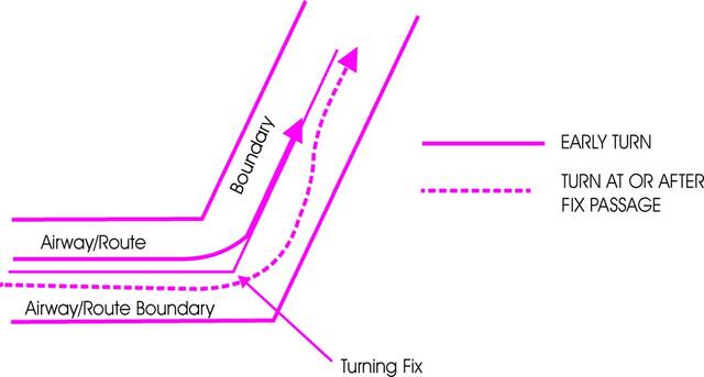
-
Special attention should be given to the parts which differ from U.S. CFRs.
-
Three fixed route systems are established for air navigation purposes. They are the Federal airway system (consisting of VOR and L/MF routes), the jet route system, and the RNAV route system. To the extent possible, these route systems are aligned in an overlying manner to facilitate transition between each.
-
Airway or Route Course Changes
- Pilots of aircraft are required to adhere to airways or routes being flown. Special attention must be given to this requirement during course changes. Each course change consists of variables that make the technique applicable in each case a matter only the pilot can resolve. Some variables which must be considered are turn radius, wind effect, airspeed, degree of turn, and cockpit instrumentation. An early turn, as illustrated below, is one method of adhering to airways or routes. The use of any available cockpit instrumentation, such as Distance Measuring Equipment, may be used by the pilot to lead the turn when making course changes. This is consistent with the intent of 14 CFR section 91.181, which requires pilots to operate along the centerline of an airway and along the direct course between navigational aids or fixes.
- Turns which begin at or after fix passage may exceed airway or route boundaries. FIG 5-3-1 contains an example flight track depicting this, together with an example of an early turn.
- Without such actions as leading a turn, aircraft operating in excess of 290 knots true air speed (TAS) can exceed the normal airway or route boundaries depending on the amount of course change required, wind direction and velocity, the character of the turn fix (DME, overhead navigation aid, or intersection), and the pilot's technique in making a course change. For example, a flight operating at 17,000 feet MSL with a TAS of 400 knots, a 25 degree bank, and a course change of more than 40 degrees would exceed the width of the airway or route; i.e., 4 nautical miles each side of centerline. However, in the airspace below 18,000 feet MSL, operations in excess of 290 knots TAS are not prevalent and the provision of additional IFR separation in all course change situations for the occasional aircraft making a turn in excess of 290 knots TAS creates an unacceptable waste of airspace and imposes a penalty upon the preponderance of traffic which operate at low speeds. Consequently, the FAA expects pilots to lead turns and take other actions they consider necessary during course changes to adhere as closely as possible to the airways or route being flown.
-
Changeover Points (COPs)
- COPs are prescribed for Federal airways, jet routes, area navigation routes, or other direct routes for which an MEA is designated under 14 CFR part 95. The COP is a point along the route or airway segment between two adjacent navigation facilities or waypoints where changeover in navigation guidance should occur. At this point, the pilot should change navigation receiver frequency from the station behind the aircraft to the station ahead.
- The COP is normally located midway between the navigation facilities for straight route segments, or at the intersection of radials or courses forming a dogleg in the case of dogleg route segments. When the COP is NOT located at the midway point, aeronautical charts will depict the COP location and give the mileage to the radio aids.
- COPs are established for the purpose of preventing loss of navigation guidance, to prevent frequency interference from other facilities, and to prevent use of different facilities by different aircraft in the same airspace. Pilots are urged to observe COPs to the fullest extent.
-
Minimum Turning Altitude (MTA)
Due to increased airspeeds at 10,000 ft MSL or above, the published minimum enroute altitude (MEA) may not be sufficient for obstacle clearance when a turn is required over a fix, NAVAID, or waypoint. In these instances, an expanded area in the vicinity of the turn point is examined to determine whether the published MEA is sufficient for obstacle clearance. In some locations (normally mountainous), terrain/obstacles in the expanded search area may necessitate a higher minimum altitude while conducting the turning maneuver. Turning fixes requiring a higher minimum turning altitude (MTA) will be denoted on government charts by the minimum crossing altitude (MCA) icon (“x" flag) and an accompanying note describing the MTA restriction. An MTA restriction will normally consist of the air traffic service (ATS) route leading to the turn point, the ATS route leading from the turn point, and the required altitude; e.g., MTA V330 E TO V520 W 16000. When an MTA is applicable for the intended route of flight, pilots must ensure they are at or above the charted MTA not later than the turn point and maintain at or above the MTA until joining the centerline of the ATS route following the turn point. Once established on the centerline following the turning fix, the MEA/MOCA determines the minimum altitude available for assignment. An MTA may also preclude the use of a specific altitude or a range of altitudes during a turn. For example, the MTA may restrict the use of 10,000 through 11,000 ft MSL. In this case, any altitude greater than 11,000 ft MSL is unrestricted, as are altitudes less than 10,000 ft MSL provided MEA/MOCA requirements are satisfied.
-
Holding
-
Whenever an aircraft is cleared to a fix other than the destination airport and delay is expected, it is the responsibility of ATC to issue complete holding instructions (unless the pattern is charted), an EFC time and best estimate of any additional en route/terminal delay.
NOTE-
Only those holding patterns depicted on U.S. government or commercially produced (meeting FAA requirements) low/high altitude en route, and area or STAR charts should be used.
- If the holding pattern is charted and the controller doesn't issue complete holding instructions, the pilot is expected to hold as depicted on the appropriate chart. When the pattern is charted on the assigned procedure or route being flown, ATC may omit all holding instructions except the charted holding direction and the statement AS PUBLISHED; for example, HOLD EAST AS PUBLISHED. ATC must always issue complete holding instructions when pilots request them.
- If no holding pattern is charted and holding instructions have not been issued, the pilot should ask ATC for holding instructions prior to reaching the fix. This procedure will eliminate the possibility of an aircraft entering a holding pattern other than that desired by ATC. If unable to obtain holding instructions prior to reaching the fix (due to frequency congestion, stuck microphone, etc.), then enter a standard pattern on the course on which the aircraft approached the fix and request further clearance as soon as possible. In this event, the altitude/flight level of the aircraft at the clearance limit will be protected so that separation will be provided as required.
- When an aircraft is 3 minutes or less from a clearance limit and a clearance beyond the fix has not been received, the pilot is expected to start a speed reduction so that the aircraft will cross the fix, initially, at or below the maximum holding airspeed.
- When no delay is expected, the controller should issue a clearance beyond the fix as soon as possible and, whenever possible, at least 5 minutes before the aircraft reaches the clearance limit.
-
Pilots should report to ATC the time and altitude/flight level at which the aircraft reaches the clearance limit and report leaving the clearance limit.
NOTE-
In the event of two‐way communications failure, pilots are required to comply with 14 CFR section 91.185.
- When holding at a VOR station, pilots should begin the turn to the outbound leg at the time of the first complete reversal of the to/from indicator.
-
Patterns at the most generally used holding fixes are depicted (charted) on U.S. Government or commercially produced (meeting FAA requirements) Low or High Altitude En Route, Area, Departure Procedure, and STAR Charts. Pilots are expected to hold in the pattern depicted unless specifically advised otherwise by ATC.
NOTE-
Holding patterns that protect for a maximum holding airspeed other than the standard may be depicted by an icon, unless otherwise depicted. The icon is a standard holding pattern symbol (racetrack) with the airspeed restriction shown in the center. In other cases, the airspeed restriction will be depicted next to the standard holding pattern symbol.
REFERENCE-
-
An ATC clearance requiring an aircraft to hold at a fix where the pattern is not charted will include the following information: (See FIG 5-3-2.)
- Direction of holding from the fix in terms of the eight cardinal compass points (i.e., N, NE, E, SE, etc.).
- Holding fix (the fix may be omitted if included at the beginning of the transmission as the clearance limit).
- Radial, course, bearing, airway or route on which the aircraft is to hold.
- Leg length in miles if DME or RNAV is to be used (leg length will be specified in minutes on pilot request or if the controller considers it necessary).
- Direction of turn if left turns are to be made, the pilot requests, or the controller considers it necessary.
-
Time to expect further clearance and any pertinent additional delay information.
FIG 5-3-2
Holding Patterns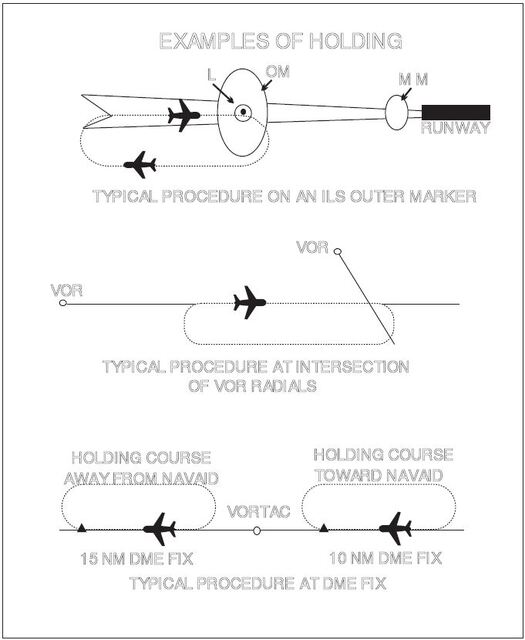
FIG 5-3-3
Holding Pattern Descriptive Terms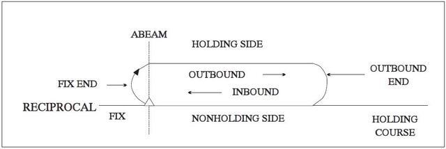
-
Holding pattern airspace protection is based on the following procedures.
-
Descriptive Terms.
- Standard Pattern. Right turns (See FIG 5-3-3.)
- Nonstandard Pattern. Left turns
-
Airspeeds.
-
All aircraft may hold at the following altitudes and maximum holding airspeeds:
TBL 5-3-20
Altitude (MSL)
Airspeed (KIAS)
MHA - 6,000'
200
6,001' - 14,000'
230
14,001' and above
265
NOTE-
These are the maximum indicated air speeds applicable to all holding.
-
The following are exceptions to the maximum holding airspeeds:
- Holding patterns from 6,001' to 14,000' may be restricted to a maximum airspeed of 210 KIAS. This nonstandard pattern will be depicted by an icon.
- Holding patterns may be restricted to a maximum speed. The speed restriction is depicted in parenthesis inside the holding pattern on the chart: e.g., (175). The aircraft should be at or below the maximum speed prior to initially crossing the holding fix to avoid exiting the protected airspace. Pilots unable to comply with the maximum airspeed restriction should notify ATC.
- Holding patterns at USAF airfields only - 310 KIAS maximum, unless otherwise depicted.
- Holding patterns at Navy fields only - 230 KIAS maximum, unless otherwise depicted.
- All helicopter/power lift aircraft holding on a “COPTER” instrument procedure is predicated on a minimum airspeed of 90 KIAS unless charted otherwise.
- When a climb-in hold is specified by a published procedure (for example, “Climb-in holding pattern to depart XYZ VORTAC at or above 10,000.” or “All aircraft climb-in TRUCK holding pattern to cross TRUCK Int at or above 11,500 before proceeding on course.”), additional obstacle protection area has been provided to allow for greater airspeeds in the climb for those aircraft requiring them. A maximum airspeed of 310 KIAS is permitted in Climb-in-holding, unless a maximum holding airspeed is published, in which case that maximum airspeed is applicable. The airspeed limitations in 14 CFR section 91.117, Aircraft Speed, still apply.
-
The following phraseology may be used by an ATCS to advise a pilot of the maximum holding airspeed for a holding pattern airspace area.
PHRASEOLOGY-
(AIRCRAFT IDENTIFICATION) (holding instructions, when needed) MAXIMUM HOLDING AIRSPEED IS (speed in knots).
FIG 5-3-4
Holding Pattern Entry Procedures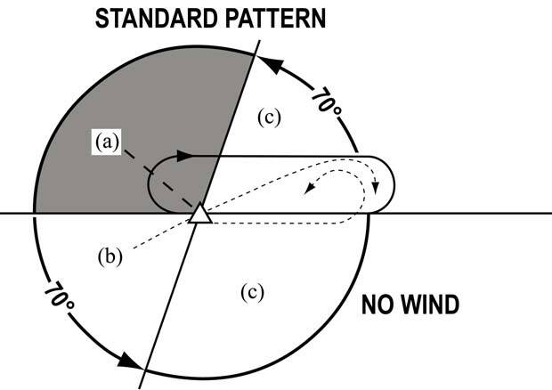
-
All aircraft may hold at the following altitudes and maximum holding airspeeds:
-
Entry Procedures. Holding protected airspace is designed based in part on pilot compliance with the three recommended holding pattern entry procedures discussed below. Deviations from these recommendations, coupled with excessive airspeed crossing the holding fix, may in some cases result in the aircraft exceeding holding protected airspace. (See FIG 5-3-4.)
- Parallel Procedure. When approaching the holding fix from anywhere in sector (a), the parallel entry procedure would be to turn to a heading to parallel the holding course outbound on the nonholding side for one minute, turn in the direction of the holding pattern through more than 180 degrees, and return to the holding fix or intercept the holding course inbound.
- Teardrop Procedure. When approaching the holding fix from anywhere in sector (b), the teardrop entry procedure would be to fly to the fix, turn outbound to a heading for a 30 degree teardrop entry within the pattern (on the holding side) for a period of one minute, then turn in the direction of the holding pattern to intercept the inbound holding course.
- Direct Entry Procedure. When approaching the holding fix from anywhere in sector (c), the direct entry procedure would be to fly directly to the fix and turn to follow the holding pattern.
- While other entry procedures may enable the aircraft to enter the holding pattern and remain within protected airspace, the parallel, teardrop and direct entries are the procedures for entry and holding recommended by the FAA, and were derived as part of the development of the size and shape of the obstacle protection areas for holding.
- Nonstandard Holding Pattern. Fix end and outbound end turns are made to the left. Entry procedures to a nonstandard pattern are oriented in relation to the 70 degree line on the holding side just as in the standard pattern.
-
Timing.
-
Inbound Leg.
- At or below 14,000 feet MSL: 1 minute.
-
Above 14,000 feet MSL: 11/2 minutes.
NOTE-
The initial outbound leg should be flown for 1 minute or 1 1/2 minutes (appropriate to altitude). Timing for subsequent outbound legs should be adjusted, as necessary, to achieve proper inbound leg time. Pilots may use any navigational means available; i.e., DME, RNAV, etc., to ensure the appropriate inbound leg times.
- Outbound leg timing begins over/abeam the fix, whichever occurs later. If the abeam position cannot be determined, start timing when turn to outbound is completed.
-
Inbound Leg.
-
Distance Measuring Equipment (DME)/ GPS Along-Track Distance (ATD). DME/GPS holding is subject to the same entry and holding procedures except that distances (nautical miles) are used in lieu of time values. The outbound course of the DME/GPS holding pattern is called the outbound leg of the pattern. The controller or the instrument approach procedure chart will specify the length of the outbound leg. The end of the outbound leg is determined by the DME or ATD readout. The holding fix on conventional procedures, or controller defined holding based on a conventional navigation aid with DME, is a specified course or radial and distances are from the DME station for both the inbound and outbound ends of the holding pattern. When flying published GPS overlay or stand alone procedures with distance specified, the holding fix will be a waypoint in the database and the end of the outbound leg will be determined by the ATD. Some GPS overlay and early stand alone procedures may have timing specified. (See FIG 5-3-5, FIG 5-3-6 and FIG 5-3-7.) See paragraph 1-1-17, Global Positioning System (GPS), for requirements and restriction on using GPS for IFR operations.
FIG 5-3-5
Inbound Toward NAVAID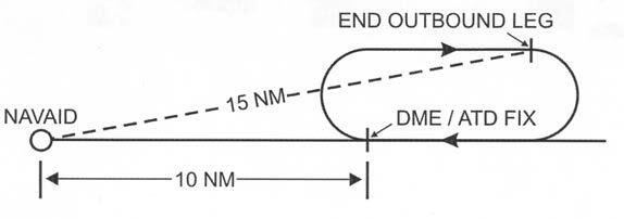
NOTE-
When the inbound course is toward the NAVAID, the fix distance is 10 NM, and the leg length is 5 NM, then the end of the outbound leg will be reached when the DME reads 15 NM.
FIG 5-3-6
Inbound Leg Away from NAVAID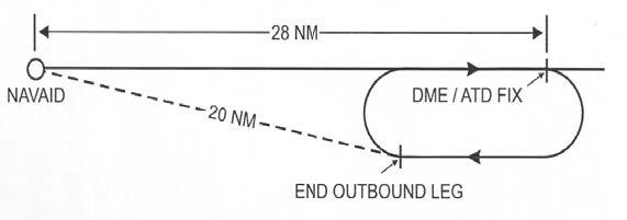
NOTE-
When the inbound course is away from the NAVAID and the fix distance is 28 NM, and the leg length is 8 NM, then the end of the outbound leg will be reached when the DME reads 20 NM.
-
Use of RNAV Distance in lieu of DME Distance. Substitution of RNAV computed distance to or from a NAVAID in place of DME distance is permitted when holding. However, the actual holding location and pattern flown will be further from the NAVAID than designed due to the lack of slant range in the position solution (see FIG 5-3-7). This may result in a slight difference between RNAV distance readout in reference to the NAVAID and the DME readout, especially at higher altitudes. When used solely for DME substitution, the difference between RNAV distance to/from a fix and DME slant range distance can be considered negligible and no pilot action is required.
REFERENCE-
AIM, Para 1-2-3, Use of Suitable Area Navigation (RNAV) Systems on Conventional Procedures and Routes.
FIG 5-3-7
Difference Between DME Distance From NAVAID & RNAV Computed Distance From NAVAID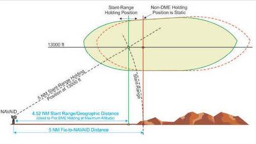
-
Use of RNAV Guidance and Holding. RNAV systems, including multi-sensor Flight Management Systems (FMS) and stand-alone GPS receivers, may be used to furnish lateral guidance when executing a hold. The manner in which holding is implemented in an RNAV system varies widely between aircraft and RNAV system manufacturers. Holding pattern data may be extracted from the RNAV database for published holds or may be manually entered for ad-hoc ATC-assigned holds. Pilots are expected to be familiar with the capabilities and limitations of the specific RNAV system used for holding.
-
All holding, including holding defined on an RNAV or RNP procedure, is based on the conventional NAVAID holding design criteria, including the holding protected airspace construction. There are differences between the holding entry and flight track assumed in conventional holding pattern design and the entry and track that may be flown when RNAV guidance is used to execute holding. Individually, these differences may not affect the ability of the aircraft to remain within holding pattern protected airspace. However, cumulatively, they can result in deviations sufficient to result in excursions up to limits of the holding pattern protected airspace, and in some circumstances beyond protected airspace. The following difference and considerations apply when an RNAV system furnishes the lateral guidance used to fly a holding pattern:
- Many systems use ground track angle instead of heading to select the entry method. While the holding pattern design allows a 5 degree tolerance, this may result in an unexpected entry when the winds induce a large drift angle.
- The holding protected airspace is based on the assumption that the aircraft will fly-over the holding fix upon initial entry. RNAV systems may execute a “fly-by” turn when approaching the holding fix prior to entry. A “fly-by” turn during a direct entry from the holding pattern side of holding course may result in excursions beyond protected airspace, especially as the intercept angle and ground speed increase.
- During holding, RNAV systems furnish lateral steering guidance using either a constant bank or constant radius to achieve the desired inbound and outbound turns. An aircraft's flight guidance system may use reduced bank angles for all turns including turns in holding, especially at higher altitudes, that may result in exceeding holding protected airspace. Use of a shallower bank angle will expand both the width and length of the aircraft track, especially as wind speed increases. If the flight guidance system's bank angle limit feature is pilot-selectable, a minimum 25 degree bank angle should be selected regardless of altitude unless aircraft operating limitations specify otherwise and the pilot advises ATC.
-
Where a holding distance is published, the turn from the outbound leg begins at the published distance from the holding fix, thus establishing the design turn point required to remain within protected airspace. RNAV systems apply a database coded or pilot-entered leg distance as a maximum length of the inbound leg to the holding fix. The RNAV system then calculates a turn point from the outbound leg required to achieve this inbound leg length. This often results in an RNAV-calculated turn point on the outbound leg beyond the design turn point. (See FIG 5-3-8). With a strong headwind against the outbound leg, RNAV systems may fly up to and possibly beyond the limits of protected airspace before turning inbound. (See FIG 5-3-9.) This is especially true at higher altitudes where wind speeds are greater and ground speed results in a wider holding pattern.
FIG 5-3-8
RNAV Lateral Guidance and Holding - No Wind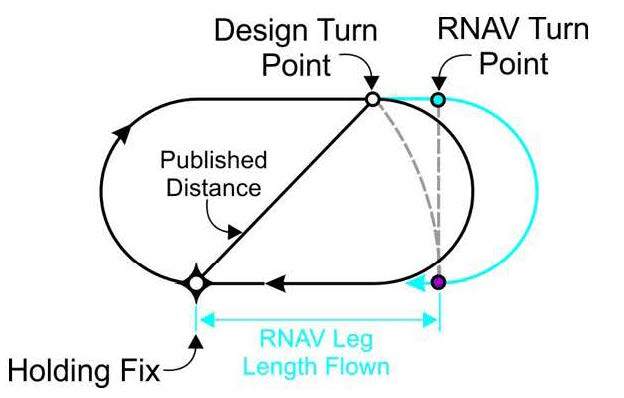
FIG 5-3-9
RNAV Lateral Guidance and Holding - Effect of Wind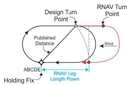
-
Some RNAV systems compute the holding pattern based on the aircraft's altitude and speed at a point prior to entering the hold. If the indicated airspeed is not reduced to comply with the maximum holding speed before this point, the computed pattern may exceed the protected airspace. Loading or executing a holding pattern may result in the speed and time limits applicable to the aircraft's current altitude being used to define the holding pattern for RNAV lateral guidance. This may result in an incorrect hold being flown by the RNAV system. For example, entering or executing the holding pattern above 14,000 feet when intending to hold below 14,000 feet may result in applying 1 ½ minute timing below 14,000 feet.
NOTE-
Some systems permit the pilot to modify leg time of holding patterns defined in the navigation database; for example, a hold-in-lieu of procedure turn. In most RNAV systems, the holding pattern time remains at the pilot-modified time and will not revert back to the coded time if the aircraft descends to a lower altitude where a shorter time interval applies.
- RNAV systems are not able to alert the pilot for excursions outside of holding pattern protected airspace since the dimensions of this airspace are not included in the navigation database. In addition, the dimensions of holding pattern protected airspace vary with altitude for a charted holding pattern, even when the hold is used for the same application. Close adherence to the pilot actions described in this section reduce the likelihood of exceeding the boundary of holding pattern protected airspace when using RNAV lateral guidance to conduct holding.
-
Holding patterns may be stored in the RNAV system's navigation database and include coding with parameters defining how the RNAV system will conduct the hold. For example, coding will determine whether holding is conducted to manual termination (HM), continued holding until the aircraft reaches a specified altitude (HA), or holding is conducted until the holding fix is crossed the first time after entry (HF). Some systems do not store all holding patterns, and may only store patterns associated with missed approaches and hold-in-lieu of procedure turn (HILPT). Some store all holding as standard patterns and require pilot action to conduct non-standard holding (left turns).
- Pilots are cautioned that multiple holding patterns may be established at the same fix. These holding patterns may differ in respect to turn directions and leg lengths depending on their application as an en route holding pattern, a holding pattern charted on a SID or STAR, or when used on an instrument approach procedure. Many RNAV systems limit the database coding at a particular fix to a single holding pattern definition. Pilots extracting the holding pattern from the navigation database are responsible for confirming that the holding pattern conforms to the assigned charted holding pattern in terms of turn direction, speed limit, timing, and distance.
- If ATC assigns holding that is not charted, then the pilot is responsible for programming the RNAV system with the assigned holding course, turn direction, speed limit, leg length, or leg time.
- Changes made after the initial execution may not apply until the next circuit of the holding pattern if the aircraft is in close proximity to the holding fix.
-
All holding, including holding defined on an RNAV or RNP procedure, is based on the conventional NAVAID holding design criteria, including the holding protected airspace construction. There are differences between the holding entry and flight track assumed in conventional holding pattern design and the entry and track that may be flown when RNAV guidance is used to execute holding. Individually, these differences may not affect the ability of the aircraft to remain within holding pattern protected airspace. However, cumulatively, they can result in deviations sufficient to result in excursions up to limits of the holding pattern protected airspace, and in some circumstances beyond protected airspace. The following difference and considerations apply when an RNAV system furnishes the lateral guidance used to fly a holding pattern:
-
Pilot Action. The following actions are recommended to ensure that the aircraft remains within holding protected airspace when holding is performed using either conventional NAVAID guidance or when using RNAV lateral guidance.
-
Speed. When ATC furnishes advance notice of holding, start speed reduction to be at or below the maximum holding speed allowed at least 3 minutes prior to crossing the holding fix. If advance notice by ATC is not provided, begin speed reduction as expeditiously as practical. It is acceptable to allow RNAV systems to determine an appropriate deceleration point prior to the holding fix and to manage the speed reduction to the RNAV computed holding speed. If the pilot does not permit the RNAV system to manage the deceleration from the computed point, the actual hold pattern size at holding entry may differ from the holding pattern size computed by the RNAV system.
-
Aircraft are expected to enter holding at or below the maximum holding speed established in paragraph 5-3-8j2(a) or the charted maximum holding speed.
- All fixed wing aircraft conducting holding should fly at speeds at or above 90 KIAS to minimize the influence of wind drift.
- When RNAV lateral guidance is used in fixed wing airplanes, it is desirable to enter and conduct holding at the lowest practical airspeed consistent with the airplane's recommended holding speed to address the cumulative errors associated with RNAV holding and increase the probability of remaining within protected airspace. It is acceptable to allow RNAV systems to determine a recommended holding speed that is at or below the maximum holding speed.
- Helicopter holding is based on a minimum airspeed of 90 KIAS.
-
Advise ATC immediately if unable to comply with the maximum holding airspeed and request an alternate clearance.
NOTE-
Speeds above the maximum or published holding speed may be necessary due to turbulence, icing, etc. Exceeding maximum holding airspeed may result in aircraft excursions beyond the holding pattern protected airspace. In a non-radar environment, the pilot should advise ATC that they cannot accept the assigned hold.
- Ensure the RNAV system applies the proper time and speed restrictions to a holding pattern. This is especially critical when climbing or descending to a holding pattern altitude where time and speed restrictions are different than at the present aircraft altitude.
-
Aircraft are expected to enter holding at or below the maximum holding speed established in paragraph 5-3-8j2(a) or the charted maximum holding speed.
-
Bank Angle. For holding not involving the use of RNAV lateral guidance, make all turns during entry and while holding at:
- 3 degrees per second, or
- 30 degree bank angle, or
-
25 degree bank angle, provided a flight director system is used.
NOTE-
Use whichever requires the least bank angle.
- When using RNAV lateral guidance to conduct holding, it is acceptable to permit the RNAV system to calculate the appropriate bank angle for the outbound and inbound turns. Do not use flight guidance system bank angle limiting functions of less than 25 degrees unless the feature is not pilot-selectable, required by the aircraft limitations, or its use is necessary to comply with the aircraft's minimum maneuvering speed margins. If the bank angle must be limited to less than 25 degrees, advise ATC that additional area for holding is required.
- Compensate for wind effect primarily by drift correction on the inbound and outbound legs. When outbound, triple the inbound drift correction to avoid major turning adjustments; for example, if correcting left by 8 degrees when inbound, correct right by 24 degrees when outbound.
- Determine entry turn from aircraft heading upon arrival at the holding fix; +/- 5 degrees in heading is considered to be within allowable good operating limits for determining entry. When using RNAV lateral guidance for holding, it is permissible to allow the system to compute the holding entry.
- RNAV lateral guidance may execute a fly-by turn beginning at an excessively large distance from the holding fix. Reducing speed to the maximum holding speed at least 3 minutes prior to reaching the holding fix and using the recommended 25 degree bank angle will reduce potential excursions beyond protected airspace.
- When RNAV guidance is used for holding, pilots should be prepared to intervene if the turn from outbound leg to the inbound leg does not begin within a reasonable distance of the charted leg length, especially when holding is used as a course reversal HILPT. Pilot intervention is not required when holding in an ATC-assigned holding pattern that is not charted. However, notify ATC when the outbound leg length becomes excessive when RNAV guidance is used for holding.
-
Speed. When ATC furnishes advance notice of holding, start speed reduction to be at or below the maximum holding speed allowed at least 3 minutes prior to crossing the holding fix. If advance notice by ATC is not provided, begin speed reduction as expeditiously as practical. It is acceptable to allow RNAV systems to determine an appropriate deceleration point prior to the holding fix and to manage the speed reduction to the RNAV computed holding speed. If the pilot does not permit the RNAV system to manage the deceleration from the computed point, the actual hold pattern size at holding entry may differ from the holding pattern size computed by the RNAV system.
-
Descriptive Terms.
- When holding at a fix and instructions are received specifying the time of departure from the fix, the pilot should adjust the aircraft's flight path within the limits of the established holding pattern in order to leave the fix at the exact time specified. After departing the holding fix, normal speed is to be resumed with respect to other governing speed requirements, such as terminal area speed limits, specific ATC requests, etc. Where the fix is associated with an instrument approach and timed approaches are in effect, a procedure turn must not be executed unless the pilot advises ATC, since aircraft holding are expected to proceed inbound on final approach directly from the holding pattern when approach clearance is received.
-
Radar surveillance of holding pattern airspace areas.
- Whenever aircraft are holding, ATC will usually provide radar surveillance of the holding airspace on the controller's radar display.
-
The controller will attempt to detect any holding aircraft that stray outside the holding airspace and will assist any detected aircraft to return to the assigned airspace.
NOTE-
Many factors could prevent ATC from providing this additional service, such as workload, number of targets, precipitation, ground clutter, and radar system capability. These circumstances may make it unfeasible to maintain radar identification of aircraft to detect aircraft straying from the holding pattern. The provision of this service depends entirely upon whether controllers believe they are in a position to provide it and does not relieve a pilot of their responsibility to adhere to an accepted ATC clearance.
- ATC is responsible for traffic and obstruction separation when they have assigned holding that is not associated with a published (charted) holding pattern. Altitudes assigned will be at or above the minimum vectoring or minimum IFR altitude.
- If an aircraft is established in a published holding pattern at an assigned altitude above the published minimum holding altitude and subsequently cleared for the approach, the pilot may descend to the published minimum holding altitude. The holding pattern would only be a segment of the IAP if it is published on the instrument procedure chart and is used in lieu of a procedure turn.
- For those holding patterns where there are no published minimum holding altitudes, the pilot, upon receiving an approach clearance, must maintain the last assigned altitude until leaving the holding pattern and established on the inbound course. Thereafter, the published minimum altitude of the route segment being flown will apply. It is expected that the pilot will be assigned a holding altitude that will permit a normal descent on the inbound course.
-
Whenever an aircraft is cleared to a fix other than the destination airport and delay is expected, it is the responsibility of ATC to issue complete holding instructions (unless the pattern is charted), an EFC time and best estimate of any additional en route/terminal delay.
Section 4. Arrival Procedures
-
Standard Terminal Arrival (STAR) Procedures
-
A STAR is an ATC coded IFR arrival route established for application to arriving IFR aircraft destined for certain airports. STARs simplify clearance delivery procedures, and also facilitate transition between en route and instrument approach procedures.
-
STAR procedures may have mandatory speeds and/or crossing altitudes published. Other STARs may have planning information depicted to inform pilots what clearances or restrictions to “expect.” “Expect” altitudes/speeds are not considered STAR procedures crossing restrictions unless verbally issued by ATC. Published speed restrictions are independent of altitude restrictions and are mandatory unless modified by ATC. Pilots should plan to cross waypoints with a published speed restriction, at the published speed, and should not exceed this speed past the associated waypoint unless authorized by ATC or a published note to do so. STAR procedures may have mandatory speeds and/or crossing altitudes published. Other STARs may have planning information depicted to inform pilots what clearances or restrictions to “expect.” “Expect” altitudes/speeds are not considered STAR procedures crossing restrictions unless verbally issued by ATC. Published speed restrictions are independent of altitude restrictions and are mandatory unless modified by ATC. Pilots should plan to cross waypoints with a published speed restriction, at the published speed, and should not exceed this speed past the associated waypoint unless authorized by ATC or a published note to do so. A chart note used to transition from Mach to IAS may also be published. Pilots should maintain their cruise Mach number during the descent until reaching the published transition speed in knots, then continue the descent at that speed until the next published speed restriction on the STAR, or until it is necessary to comply with the speed limits published in 14 CFR §91.117.
NOTE-
The “expect” altitudes/speeds are published so that pilots may have the information for planning purposes. These altitudes/speeds must not be used in the event of lost communications unless ATC has specifically advised the pilot to expect these altitudes/speeds as part of a further clearance.
REFERENCE-
14 CFR section 91.185(c)(2)(iii).
-
When an IFR cleared route includes a STAR, pilots must maintain the last assigned altitude until receiving authorization to descend so as to comply with all published/issued altitude restrictions. This authorization may contain the phraseology “DESCEND VIA.” If vectored or cleared to deviate off a STAR, pilots must consider the STAR canceled. If the STAR contains published altitude restrictions, speed restrictions, or a chart note used to transition from Mach to IAS, those restrictions are also canceled and pilots will receive an altitude to maintain and, if necessary, a speed. If ATC intends to clear the aircraft back onto the STAR, controllers will advise pilots where to expect to resume the procedure. Pilots should then be prepared to rejoin the STAR at the subsequent fix or procedure leg.
-
Clearance to “descend via” authorizes pilots to:
- Descend at pilot's discretion to meet published restrictions and laterally navigate on a STAR.
- When cleared to a waypoint depicted on a STAR, to descend from a previously assigned altitude at pilot's discretion to the altitude depicted at that waypoint.
-
Once established on the depicted arrival, to descend and to meet all published or assigned altitude and/or speed restrictions.
NOTE-
- When otherwise cleared along a route or procedure that contains published speed restrictions, the pilot must comply with those speed restrictions independent of any descend via clearance.
- ATC anticipates pilots will begin adjusting speed the minimum distance necessary prior to a published speed restriction so as to cross the waypoint/fix at the published speed. Once at the published speed, ATC expects pilots will maintain the published speed until additional adjustment is required to comply with further published or ATC assigned speed restrictions or as required to ensure compliance with 14 CFR section 91.117.
- The “descend via” is used in conjunction with STARs to reduce phraseology by not requiring the controller to restate the altitude at the next waypoint/fix to which the pilot has been cleared.
- Air traffic will assign an altitude to cross the waypoint/ fix, if no altitude is depicted at the waypoint/fix, for aircraft on a direct routing to a STAR. Air traffic must ensure obstacle clearance when issuing a “descend via” instruction to the pilot.
- Minimum en route altitudes (MEA) are not considered restrictions; however, pilots must remain above all MEAs, unless receiving an ATC instruction to descend below the MEA.
EXAMPLE-
- Lateral/routing clearance only.
“Cleared Tyler One arrival.”
NOTE-
In Example 1, pilots are cleared to fly the lateral path of the procedure. Compliance with any published speed restrictions is required. No descent is authorized.
- Routing with assigned altitude.
“Cleared Tyler One arrival, descend and maintain flight level two four zero.”
“Cleared Tyler One arrival, descend at pilot's discretion, maintain flight level two four zero.”
NOTE-
In Example 2, the first clearance requires the pilot to descend to FL 240 as directed, comply with any published speed restrictions, and maintain FL 240 until cleared for further vertical navigation with a newly assigned altitude or a“descend via” clearance.
The second clearance authorizes the pilot to descend to FL 240 at his discretion, to comply with any published speed restrictions, and then maintain FL 240 until issued further instructions.- Lateral/routing and vertical navigation clearance.
“Descend via the Eagul Five arrival.”
“Descend via the Eagul Five arrival, except, cross Vnnom at or above one two thousand.”
NOTE-
In Example 3, the first clearance authorized the aircraft to descend at pilot's discretion on the Eagul Five arrival; the pilot must descend so as to comply with all published altitude and speed restrictions.
The second clearance authorizes the same, but requires the pilot to descend so as to cross at Vnnom at or above 12,000.- Lateral/routing and vertical navigation clearance when assigning altitude not published on procedure.
“Descend via the Eagul Five arrival, except after Geeno, maintain one zero thousand.”
“Descend via the Eagul Five arrival, except cross Geeno at one one thousand then maintain seven thousand.”
NOTE-
In Example 4, the first clearance authorized the aircraft to track laterally on the Eagul Five Arrival and to descend at pilot's discretion so as to comply with all altitude and speed restrictions until reaching Geeno and then maintain 10,000. Upon reaching 10,000, aircraft should maintain 10,000 until cleared by ATC to continue to descend.
The second clearance requires the same, except the aircraft must cross Geeno at 11,000 and is then authorized to continue descent to and maintain 7,000.- Direct routing to intercept a STAR and vertical navigation clearance.
“Proceed direct Leoni, descend via the Leoni One arrival.”
“Proceed direct Denis, cross Denis at or above flight level two zero zero, then descend via the Mmell One arrival.”
NOTE-
In Example 5, in the first clearance an altitude is published at Leoni; the aircraft proceeds to Leoni, crosses Leoni at the published altitude and then descends via the arrival. If a speed restriction is published at Leoni, the aircraft will slow to comply with the published speed.
In the second clearance, there is no altitude published at Denis; the aircraft must cross Denis at or above FL200, and then descends via the arrival.
-
Pilots cleared for vertical navigation using the phraseology “descend via” must inform ATC upon initial contact with a new frequency, of the altitude leaving, “descending via (procedure name),” the runway transition or landing direction if assigned, and any assigned restrictions not published on the procedure.
EXAMPLE-
- Delta 121 is cleared to descend via the Eagul Five arrival, runway 26 transition:
“Delta One Twenty One leaving flight level one niner zero, descending via the Eagul Five arrival runway two-six transition.” - Delta 121 is cleared to descend via the Eagul Five arrival, but ATC has changed the bottom altitude to 12,000:
“Delta One Twenty One leaving flight level one niner zero for one two thousand, descending via the Eagul Five arrival, runway two-six transition.” - (JetBlue 602 is cleared to descend via the Ivane Two arrival, landing south):
“JetBlue six zero two leaving flight level two one zero descending via the Ivane Two arrival landing south.”
- Delta 121 is cleared to descend via the Eagul Five arrival, runway 26 transition:
-
Clearance to “descend via” authorizes pilots to:
-
STAR procedures may have mandatory speeds and/or crossing altitudes published. Other STARs may have planning information depicted to inform pilots what clearances or restrictions to “expect.” “Expect” altitudes/speeds are not considered STAR procedures crossing restrictions unless verbally issued by ATC. Published speed restrictions are independent of altitude restrictions and are mandatory unless modified by ATC. Pilots should plan to cross waypoints with a published speed restriction, at the published speed, and should not exceed this speed past the associated waypoint unless authorized by ATC or a published note to do so. STAR procedures may have mandatory speeds and/or crossing altitudes published. Other STARs may have planning information depicted to inform pilots what clearances or restrictions to “expect.” “Expect” altitudes/speeds are not considered STAR procedures crossing restrictions unless verbally issued by ATC. Published speed restrictions are independent of altitude restrictions and are mandatory unless modified by ATC. Pilots should plan to cross waypoints with a published speed restriction, at the published speed, and should not exceed this speed past the associated waypoint unless authorized by ATC or a published note to do so. A chart note used to transition from Mach to IAS may also be published. Pilots should maintain their cruise Mach number during the descent until reaching the published transition speed in knots, then continue the descent at that speed until the next published speed restriction on the STAR, or until it is necessary to comply with the speed limits published in 14 CFR §91.117.
- Pilots of IFR aircraft destined to locations for which STARs have been published may be issued a clearance containing a STAR whenever ATC deems it appropriate.
- Use of STARs requires pilot possession of at least the approved chart. RNAV STARs must be retrievable by the procedure name from the aircraft database and conform to charted procedure. As with any ATC clearance or portion thereof, it is the responsibility of each pilot to accept or refuse an issued STAR. Pilots should notify ATC if they do not wish to use a STAR by placing “NO STAR” in the remarks section of the flight plan or by the less desirable method of verbally stating the same to ATC.
- STAR charts are published in the Terminal Procedures Publications (TPP) and are available on subscription from the National Aeronautical Charting Office.
-
PBN STAR.
- Public PBN STARs are normally designed using RNAV 1, RNP 1, or A-RNP NavSpecs. These procedures require system performance currently met by GPS or DME/DME/IRU PBN systems that satisfy the criteria discussed in AC 90-100A, U.S. Terminal and En Route Area Navigation (RNAV) Operations. These procedures, using RNAV 1 and RNP 1 NavSpecs, must maintain a total system error of not more than 1 NM for 95% of the total flight time. Minimum values for A-RNP procedures will be charted in the PBN box (for example, 1.00 or 0.30).
- In the U.S., a specific procedure's PBN requirements will be prominently displayed in separate, standardized notes boxes. For procedures with PBN elements, the “PBN box” will contain the procedure's NavSpec(s); and, if required: specific sensors or infrastructure needed for the navigation solution, any additional or advanced functional requirements, the minimum RNP value, and any amplifying remarks. Items listed in this PBN box are REQUIRED for the procedure's PBN elements.
-
A STAR is an ATC coded IFR arrival route established for application to arriving IFR aircraft destined for certain airports. STARs simplify clearance delivery procedures, and also facilitate transition between en route and instrument approach procedures.
-
Local Flow Traffic Management Program
- This program is a continuing effort by the FAA to enhance safety, minimize the impact of aircraft noise and conserve aviation fuel. The enhancement of safety and reduction of noise is achieved in this program by minimizing low altitude maneuvering of arriving turbojet and turboprop aircraft weighing more than 12,500 pounds and, by permitting departure aircraft to climb to higher altitudes sooner, as arrivals are operating at higher altitudes at the points where their flight paths cross. The application of these procedures also reduces exposure time between controlled aircraft and uncontrolled aircraft at the lower altitudes in and around the terminal environment. Fuel conservation is accomplished by absorbing any necessary arrival delays for aircraft included in this program operating at the higher and more fuel efficient altitudes.
- A fuel efficient descent is basically an uninterrupted descent (except where level flight is required for speed adjustment) from cruising altitude to the point when level flight is necessary for the pilot to stabilize the aircraft on final approach. The procedure for a fuel efficient descent is based on an altitude loss which is most efficient for the majority of aircraft being served. This will generally result in a descent gradient window of 250-350 feet per nautical mile.
- When crossing altitudes and speed restrictions are issued verbally or are depicted on a chart, ATC will expect the pilot to descend first to the crossing altitude and then reduce speed. Verbal clearances for descent will normally permit an uninterrupted descent in accordance with the procedure as described in paragraph b above. Acceptance of a charted fuel efficient descent (Runway Profile Descent) clearance requires the pilot to adhere to the altitudes, speeds, and headings depicted on the charts unless otherwise instructed by ATC. PILOTS RECEIVING A CLEARANCE FOR A FUEL EFFICIENT DESCENT ARE EXPECTED TO ADVISE ATC IF THEY DO NOT HAVE RUNWAY PROFILE DESCENT CHARTS PUBLISHED FOR THAT AIRPORT OR ARE UNABLE TO COMPLY WITH THE CLEARANCE.
-
Approach Control
- Approach control is responsible for controlling all instrument flight operating within its area of responsibility. Approach control may serve one or more airfields, and control is exercised primarily by direct pilot and controller communications. Prior to arriving at the destination radio facility, instructions will be received from ARTCC to contact approach control on a specified frequency.
-
Radar Approach Control.
-
Where radar is approved for approach control service, it is used not only for radar approaches (Airport Surveillance Radar [ASR] and Precision Approach Radar [PAR]) but is also used to provide vectors in conjunction with published nonradar approaches based on radio NAVAIDs (ILS, VOR, NDB, TACAN). Radar vectors can provide course guidance and expedite traffic to the final approach course of any established IAP or to the traffic pattern for a visual approach. Approach control facilities that provide this radar service will operate in the following manner:
- Arriving aircraft are either cleared to an outer fix most appropriate to the route being flown with vertical separation and, if required, given holding information or, when radar handoffs are effected between the ARTCC and approach control, or between two approach control facilities, aircraft are cleared to the airport or to a fix so located that the handoff will be completed prior to the time the aircraft reaches the fix. When radar handoffs are utilized, successive arriving flights may be handed off to approach control with radar separation in lieu of vertical separation.
- After release to approach control, aircraft are vectored to the final approach course (ILS, RNAV, GLS, VOR, ADF, etc.). Radar vectors and altitude or flight levels will be issued as required for spacing and separating aircraft. Therefore, pilots must not deviate from the headings issued by approach control. Aircraft will normally be informed when it is necessary to vector across the final approach course for spacing or other reasons. If approach course crossing is imminent and the pilot has not been informed that the aircraft will be vectored across the final approach course, the pilot should query the controller.
- The pilot is not expected to turn inbound on the final approach course unless an approach clearance has been issued. This clearance will normally be issued with the final vector for interception of the final approach course, and the vector will be such as to enable the pilot to establish the aircraft on the final approach course prior to reaching the final approach fix.
- In the case of aircraft already inbound on the final approach course, approach clearance will be issued prior to the aircraft reaching the final approach fix. When established inbound on the final approach course, radar separation will be maintained and the pilot will be expected to complete the approach utilizing the approach aid designated in the clearance (ILS, RNAV, GLS, VOR, radio beacons, etc.) as the primary means of navigation. Therefore, once established on the final approach course, pilots must not deviate from it unless a clearance to do so is received from ATC.
- After passing the final approach fix on final approach, aircraft are expected to continue inbound on the final approach course and complete the approach or effect the missed approach procedure published for that airport.
- ARTCCs are approved for and may provide approach control services to specific airports. The radar systems used by these centers do not provide the same precision as an ASR/PAR used by approach control facilities and towers, and the update rate is not as fast. Therefore, pilots may be requested to report established on the final approach course.
- Whether aircraft are vectored to the appropriate final approach course or provide their own navigation on published routes to it, radar service is automatically terminated when the landing is completed or when instructed to change to advisory frequency at uncontrolled airports, whichever occurs first.
-
Where radar is approved for approach control service, it is used not only for radar approaches (Airport Surveillance Radar [ASR] and Precision Approach Radar [PAR]) but is also used to provide vectors in conjunction with published nonradar approaches based on radio NAVAIDs (ILS, VOR, NDB, TACAN). Radar vectors can provide course guidance and expedite traffic to the final approach course of any established IAP or to the traffic pattern for a visual approach. Approach control facilities that provide this radar service will operate in the following manner:
-
Advance Information on Instrument Approach
- When landing at airports with approach control services and where two or more IAPs are published, pilots will be provided in advance of their arrival with the type of approach to expect or that they may be vectored for a visual approach. This information will be broadcast either by a controller or on ATIS. It will not be furnished when the visibility is three miles or better and the ceiling is at or above the highest initial approach altitude established for any low altitude IAP for the airport.
- The purpose of this information is to aid the pilot in planning arrival actions; however, it is not an ATC clearance or commitment and is subject to change. Pilots should bear in mind that fluctuating weather, shifting winds, blocked runway, etc., are conditions which may result in changes to approach information previously received. It is important that pilots advise ATC immediately they are unable to execute the approach ATC advised will be used, or if they prefer another type of approach.
-
Aircraft destined to uncontrolled airports, which have automated weather data with broadcast capability, should monitor the ASOS/AWOS frequency to ascertain the current weather for the airport. The pilot must advise ATC when he/she has received the broadcast weather and state his/her intentions.
NOTE-
- ASOS/AWOS should be set to provide one-minute broadcast weather updates at uncontrolled airports that are without weather broadcast capability by a human observer.
- Controllers will consider the long line disseminated weather from an automated weather system at an uncontrolled airport as trend and planning information only and will rely on the pilot for current weather information for the airport. If the pilot is unable to receive the current broadcast weather, the last long line disseminated weather will be issued to the pilot. When receiving IFR services, the pilot/aircraft operator is responsible for determining if weather/visibility is adequate for approach/landing.
- When making an IFR approach to an airport not served by a tower or FSS, after ATC advises “CHANGE TO ADVISORY FREQUENCY APPROVED” you should broadcast your intentions, including the type of approach being executed, your position, and when over the final approach fix inbound (nonprecision approach) or when over the outer marker or fix used in lieu of the outer marker inbound (precision approach). Continue to monitor the appropriate frequency (UNICOM, etc.) for reports from other pilots.
-
Instrument Approach Procedure (IAP) Charts
-
14 CFR section 91.175(a), Instrument approaches to civil airports, requires the use of SIAPs prescribed for the airport in 14 CFR part 97 unless otherwise authorized by the Administrator (including ATC). If there are military procedures published at a civil airport, aircraft operating under 14 CFR part 91 must use the civil procedure(s). Civil procedures are defined with “FAA” in parenthesis; e.g., (FAA), at the top, center of the procedure chart. DoD procedures are defined using the abbreviation of the applicable military service in parenthesis; e.g., (USAF), (USN), (USA). 14 CFR section 91.175(g), Military airports, requires civil pilots flying into or out of military airports to comply with the IAPs and takeoff and landing minimums prescribed by the authority having jurisdiction at those airports. Unless an emergency exists, civil aircraft operating at military airports normally require advance authorization, commonly referred to as “Prior Permission Required” or “PPR.” Information on obtaining a PPR for a particular military airport can be found in the Chart Supplement.
NOTE-
Civil aircraft may conduct practice VFR approaches using DoD instrument approach procedures when approved by the air traffic controller.
- IAPs (standard and special, civil and military) are based on joint civil and military criteria contained in the U.S. Standard for TERPS. The design of IAPs based on criteria contained in TERPS, takes into account the interrelationship between airports, facilities, and the surrounding environment, terrain, obstacles, noise sensitivity, etc. Appropriate altitudes, courses, headings, distances, and other limitations are specified and, once approved, the procedures are published and distributed by government and commercial cartographers as instrument approach charts.
- Not all IAPs are published in chart form. Radar IAPs are established where requirements and facilities exist but they are printed in tabular form in appropriate U.S. Government Flight Information Publications.
-
The navigation equipment required to join and fly an instrument approach procedure is indicated by the title of the procedure and notes on the chart.
-
Straight-in IAPs are identified by the navigational system providing the final approach guidance and the runway to which the approach is aligned (e.g., VOR RWY 13). Circling only approaches are identified by the navigational system providing final approach guidance and a letter (e.g., VOR A). More than one navigational system separated by a slash indicates that more than one type of equipment must be used to execute the final approach (e.g., VOR/DME RWY 31). More than one navigational system separated by the word “or” indicates either type of equipment may be used to execute the final approach (e.g., VOR or GPS RWY 15).
NOTE-
This procedure identification method has changed and these procedures will be revised in the course of the normal procedure amendment process. The slash and equipment (e.g., /DME) information will be removed with future amendments. Pilots should review the procedure's notes, planview annotations, and PBN/equipment requirements boxes to determine the capability needed to accomplish the procedure.
-
In some cases, other types of navigation systems including radar may be required to execute other portions of the approach or to navigate to the IAF (e.g., an NDB procedure turn to an ILS, an NDB in the missed approach, or radar required to join the procedure or identify a fix). When radar or other equipment is required for procedure entry from the en route environment, a note will be charted in the planview of the approach procedure chart (e.g., RADAR REQUIRED or ADF REQUIRED). When radar or other equipment is required on portions of the procedure outside the final approach segment, including the missed approach, a note will be charted in the notes box of the pilot briefing portion of the approach chart (e.g., RADAR REQUIRED or DME REQUIRED). Notes are not charted when VOR is required outside the final approach segment. Pilots should ensure that the aircraft is equipped with the required NAVAID(s) in order to execute the approach, including the missed approach.
NOTE-
Some military (i.e., U.S. Air Force and U.S. Navy) IAPs have these “additional equipment required" notes charted only in the planview of the approach procedure and do not conform to the same application standards used by the FAA.
- The FAA has initiated a program to provide a new notation for LOC approaches when charted on an ILS approach requiring other navigational aids to fly the final approach course. The LOC minimums will be annotated with the NAVAID required (e.g., “DME Required” or “RADAR Required”). During the transition period, ILS approaches will still exist without the annotation.
- Many ILS approaches having minima based on RVR are eligible for a landing minimum of RVR 1800. Some of these approaches are to runways that have touchdown zone and centerline lights. For many runways that do not have touchdown and centerline lights, it is still possible to allow a landing minimum of RVR 1800. For these runways, the normal ILS minimum of RVR 2400 can be annotated with a single or double asterisk or the dagger symbol “†”; for example “** 696/24 200 (200/1/2).” A note is included on the chart stating “**RVR 1800 authorized with use of FD or AP or HUD to DA.” The pilot must use the flight director, or autopilot with an approved approach coupler, or head up display to decision altitude or to the initiation of a missed approach. In the interest of safety, single pilot operators should not fly approaches to 1800 RVR minimums on runways without touchdown and centerline lights using only a flight director, unless accompanied by the use of an autopilot with an approach coupler.
- The naming of multiple approaches of the same type to the same runway is also changing. Multiple approaches with the same guidance will be annotated with an alphabetical suffix beginning at the end of the alphabet and working backwards for subsequent procedures (e.g., ILS Z RWY 28, ILS Y RWY 28, etc.). The existing annotations such as ILS 2 RWY 28 or Silver ILS RWY 28 will be phased out and replaced with the new designation. The Cat II and Cat III designations are used to differentiate between multiple ILSs to the same runway unless there are multiples of the same type.
- RNAV (GPS) approaches to LNAV, LP, LNAV/VNAV and LPV lines of minima using WAAS and RNAV (GPS) approaches to LNAV and LNAV/VNAV lines of minima using GPS are charted as RNAV (GPS) RWY (Number) (e.g., RNAV (GPS) RWY 21).
- Performance-Based Navigation (PBN) Box. As charts are updated, a procedure's PBN requirements and conventional equipment requirements will be prominently displayed in separate, standardized notes boxes. For procedures with PBN elements, the PBN box will contain the procedure's navigation specification(s); and, if required: specific sensors or infrastructure needed for the navigation solution, any additional or advanced functional requirements, the minimum Required Navigation Performance (RNP) value, and any amplifying remarks. Items listed in this PBN box are REQUIRED for the procedure's PBN elements. For example, an ILS with an RNAV missed approach would require a specific capability to fly the missed approach portion of the procedure. That required capability will be listed in the PBN box. The separate Equipment Requirements box will list ground-based equipment requirements. On procedures with both PBN elements and equipment requirements, the PBN requirements box will be listed first. The publication of these notes will continue incrementally until all charts have been amended to comply with the new standard.
-
Straight-in IAPs are identified by the navigational system providing the final approach guidance and the runway to which the approach is aligned (e.g., VOR RWY 13). Circling only approaches are identified by the navigational system providing final approach guidance and a letter (e.g., VOR A). More than one navigational system separated by a slash indicates that more than one type of equipment must be used to execute the final approach (e.g., VOR/DME RWY 31). More than one navigational system separated by the word “or” indicates either type of equipment may be used to execute the final approach (e.g., VOR or GPS RWY 15).
-
Approach minimums are based on the local altimeter setting for that airport, unless annotated otherwise; e.g., Oklahoma City/Will Rogers World approaches are based on having a Will Rogers World altimeter setting. When a different altimeter source is required, or more than one source is authorized, it will be annotated on the approach chart; e.g., use Sidney altimeter setting, if not received, use Scottsbluff altimeter setting. Approach minimums may be raised when a nonlocal altimeter source is authorized. When more than one altimeter source is authorized, and the minima are different, they will be shown by separate lines in the approach minima box or a note; e.g., use MHK altimeter setting; when not available use SLN altimeter setting and increase all MDAs 40 feet. The altimeter source location may be referenced by city name, city and state, airport name, or the FAA location identifier. When using the location identifier, an airport outside the contiguous U.S. will use both the FAA and ICAO identifiers. New approach procedures and future amendments of existing procedures will use airport identifiers as the standard reference. When the altimeter must be obtained from a source other than air traffic a note will indicate the source; e.g., Obtain local altimeter setting on CTAF. When the altimeter setting(s) on which the approach is based is not available, the approach is not authorized. Baro-VNAV must be flown using the local altimeter setting only. Where no local altimeter is available, the LNAV/VNAV line will still be published for use by WAAS receivers with a note that Baro-VNAV is not authorized. When a local and at least one other altimeter setting source is authorized and the local altimeter is not available Baro-VNAV is not authorized; however, the LNAV/VNAV minima can still be used by WAAS receivers using the alternate altimeter setting source.
NOTE-
Barometric Vertical Navigation (baro-VNAV). An RNAV system function which uses barometric altitude information from the aircraft's altimeter to compute and present a vertical guidance path to the pilot. The specified vertical path is computed as a geometric path, typically computed between two waypoints or an angle based computation from a single waypoint. Further guidance may be found in Advisory Circular 90-105.
- A pilot adhering to the altitudes, flight paths, and weather minimums depicted on the IAP chart or vectors and altitudes issued by the radar controller, is assured of terrain and obstruction clearance and runway or airport alignment during approach for landing.
- IAPs are designed to provide an IFR descent from the en route environment to a point where a safe landing can be made. They are prescribed and approved by appropriate civil or military authority to ensure a safe descent during instrument flight conditions at a specific airport. It is important that pilots understand these procedures and their use prior to attempting to fly instrument approaches.
-
TERPS criteria are provided for the following types of instrument approach procedures:
- Precision Approach (PA). An instrument approach based on a navigation system that provides course and glidepath deviation information meeting the precision standards of ICAO Annex 10. For example, PAR, ILS, and GLS are precision approaches.
- Approach with Vertical Guidance (APV). An instrument approach based on a navigation system that is not required to meet the precision approach standards of ICAO Annex 10 but provides course and glidepath deviation information. For example, Baro-VNAV, LDA with glidepath, LNAV/VNAV and LPV are APV approaches.
- Nonprecision Approach (NPA). An instrument approach based on a navigation system which provides course deviation information, but no glidepath deviation information. For example, VOR, NDB and LNAV. As noted in subparagraph k, Vertical Descent Angle (VDA) on Nonprecision Approaches, some approach procedures may provide a Vertical Descent Angle as an aid in flying a stabilized approach, without requiring its use in order to fly the procedure. This does not make the approach an APV procedure, since it must still be flown to an MDA and has not been evaluated with a glidepath.
-
The method used to depict prescribed altitudes on instrument approach charts differs according to techniques employed by different chart publishers. Prescribed altitudes may be depicted in four different configurations: minimum, maximum, mandatory, and recommended. The U.S. Government distributes charts produced by National Geospatial-Intelligence Agency (NGA) and FAA. Altitudes are depicted on these charts in the profile view with underscore, overscore, both or none to identify them as minimum, maximum, mandatory or recommended.
- Minimum altitude will be depicted with the altitude value underscored. Aircraft are required to maintain altitude at or above the depicted value, e.g., 3000.
- Maximum altitude will be depicted with the altitude value overscored. Aircraft are required to maintain altitude at or below the depicted value, e.g., 4000.
- Mandatory altitude will be depicted with the altitude value both underscored and overscored. Aircraft are required to maintain altitude at the depicted value, e.g., 5000.
-
Recommended altitude will be depicted with no overscore or underscore. These altitudes are depicted for descent planning, e.g., 6000.
NOTE-
- Pilots are cautioned to adhere to altitudes as prescribed because, in certain instances, they may be used as the basis for vertical separation of aircraft by ATC. When a depicted altitude is specified in the ATC clearance, that altitude becomes mandatory as defined above.
- The ILS glide slope is intended to be intercepted at the published glide slope intercept altitude. This point marks the PFAF and is depicted by the ”lightning bolt” symbol on U.S. Government charts. Intercepting the glide slope at this altitude marks the beginning of the final approach segment and ensures required obstacle clearance during descent from the glide slope intercept altitude to the lowest published decision altitude for the approach. Interception and tracking of the glide slope prior to the published glide slope interception altitude does not necessarily ensure that minimum, maximum, and/or mandatory altitudes published for any preceding fixes will be complied with during the descent. If the pilot chooses to track the glide slope prior to the glide slope interception altitude, they remain responsible for complying with published altitudes for any preceding stepdown fixes encountered during the subsequent descent.
- Approaches used for simultaneous (parallel) independent and simultaneous close parallel operations procedurally require descending on the glideslope from the altitude at which the approach clearance is issued (refer to 5-4-15 and 5-4-16). For simultaneous close parallel (PRM) approaches, the Attention All Users Page (AAUP) may publish a note which indicates that descending on the glideslope/glidepath meets all crossing restrictions. However, if no such note is published, and for simultaneous independent approaches (4300 and greater runway separation) where an AAUP is not published, pilots are cautioned to monitor their descent on the glideslope/path outside of the PFAF to ensure compliance with published crossing restrictions during simultaneous operations.
- When parallel approach courses are less than 2500 feet apart and reduced in-trail spacing is authorized for simultaneous dependent operations, a chart note will indicate that simultaneous operations require use of vertical guidance and that the pilot should maintain last assigned altitude until established on glide slope. These approaches procedurally require utilization of the ILS glide slope for wake turbulence mitigation. Pilots should not confuse these simultaneous dependent operations with (SOIA) simultaneous close parallel PRM approaches, where PRM appears in the approach title.
- Altitude restrictions depicted at stepdown fixes within the final approach segment are applicable only when flying a Non-Precision Approach to a straight-in or circling line of minima identified as an MDA (H). These altitude restrictions may be annotated with a note “LOC only” or “LNAV only.” Stepdown fix altitude restrictions within the final approach segment do not apply to pilots using Precision Approach (ILS) or Approach with Vertical Guidance (LPV, LNAV/VNAV) lines of minima identified as a DA(H), since obstacle clearance on these approaches is based on the aircraft following the applicable vertical guidance. Pilots are responsible for adherence to stepdown fix altitude restrictions when outside the final approach segment (i.e., initial or intermediate segment), regardless of which type of procedure the pilot is flying. (See FIG 5-4-1.)
-
The Minimum Safe Altitudes (MSA) is published for emergency use on IAP or departure procedure (DP) graphic charts. MSAs provide 1,000 feet of clearance over all obstacles, but do not necessarily assure acceptable navigation signal coverage. The MSA depiction on the plan view of an approach chart or on a DP graphic chart contains the identifier of the center point of the MSA, the applicable radius of the MSA, a depiction of the sector(s), and the minimum altitudes above mean sea level which provide obstacle clearance. For conventional navigation systems, the MSA is normally based on the primary omnidirectional facility on which the IAP or DP graphic chart is predicated, but may be based on the airport reference point (ARP) if no suitable facility is available. For RNAV approaches or DP graphic charts, the MSA is based on an RNAV waypoint. MSAs normally have a 25 NM radius; however, for conventional navigation systems, this radius may be expanded to 30 NM if necessary to encompass the airport landing surfaces. A single sector altitude is normally established, however when the MSA is based on a facility and it is necessary to obtain relief from obstacles, an MSA with up to four sectors may be established.
FIG 5-4-1
Instrument Approach Procedure Stepdown Fixes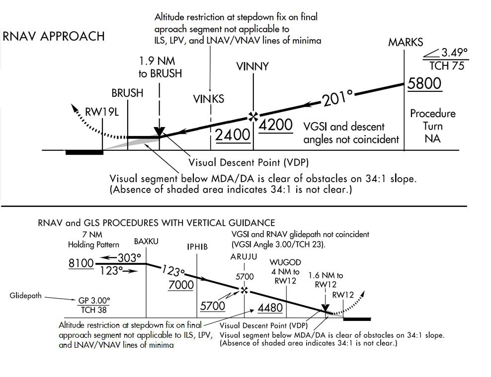
-
Terminal Arrival Area (TAA)
- The TAA provides a transition from the en route structure to the terminal environment with little required pilot/air traffic control interface for aircraft equipped with Area Navigation (RNAV) systems. A TAA provides minimum altitudes with standard obstacle clearance when operating within the TAA boundaries. TAAs are primarily used on RNAV approaches but may be used on an ILS approach when RNAV is the sole means for navigation to the IF; however, they are not normally used in areas of heavy concentration of air traffic.
-
The basic design of the RNAV procedure underlying the TAA is normally the “T” design (also called the “Basic T”). The “T” design incorporates two IAFs plus a dual purpose IF/IAF that functions as both an intermediate fix and an initial approach fix. The T configuration continues from the IF/IAF to the final approach fix (FAF) and then to the missed approach point (MAP). The two base leg IAFs are typically aligned in a straight-line perpendicular to the intermediate course connecting at the IF/IAF. A Hold-in-Lieu-of Procedure Turn (HILPT) is anchored at the IF/IAF and depicted on U.S. Government publications using the “hold-in-lieu -of-PT” holding pattern symbol. When the HILPT is necessary for course alignment and/or descent, the dual purpose IF/IAF serves as an IAF during the entry into the pattern. Following entry into the HILPT pattern and when flying a route or sector labeled “NoPT," the dual-purpose fix serves as an IF, marking the beginning of the Intermediate Segment. See FIG 5-4-2 and FIG 5-4-3 for the Basic “T” TAA configuration.
FIG 5-4-2
Basic “T” Design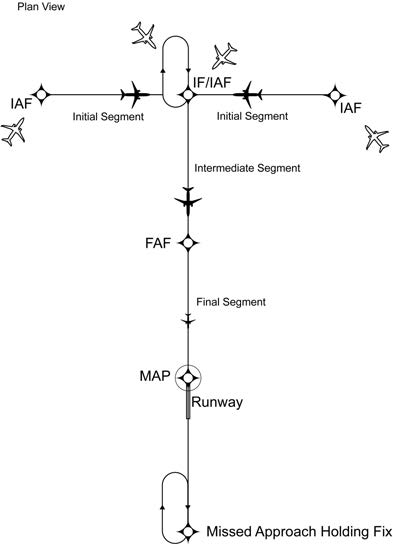
FIG 5-4-3
Basic “T” Design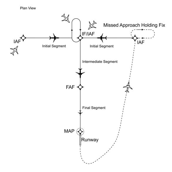
-
The standard TAA based on the “T” design consists of three areas defined by the Initial Approach Fix (IAF) legs and the intermediate segment course beginning at the IF/IAF. These areas are called the straight-in, left-base, and right-base areas. (See FIG 5-4-4). TAA area lateral boundaries are identified by magnetic courses TO the IF/IAF. The straight-in area can be further divided into pie-shaped sectors with the boundaries identified by magnetic courses TO the (IF/ IAF), and may contain stepdown sections defined by arcs based on RNAV distances from the IF/IAF. (See FIG 5-4-5). The right/left-base areas can only be subdivided using arcs based on RNAV distances from the IAFs for those areas.
FIG 5-4-4
TAA Area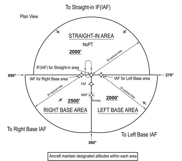
-
Entry from the terminal area onto the procedure is normally accomplished via a no procedure turn (NoPT) routing or via a course reversal maneuver. The published procedure will be annotated “NoPT” to indicate when the course reversal is not authorized when flying within a particular TAA sector. Otherwise, the pilot is expected to execute the course reversal under the provisions of 14 CFR section 91.175. The pilot may elect to use the course reversal pattern when it is not required by the procedure, but must receive clearance from air traffic control before beginning the procedure.
- ATC should not clear an aircraft to the left base leg or right base leg IAF within a TAA at an intercept angle exceeding 90 degrees. Pilots must not execute the HILPT course reversal when the sector or procedure segment is labeled “NoPT.”
-
ATC may clear aircraft direct to the fix labeled IF/IAF if the course to the IF/IAF is within the straight-in sector labeled “NoPT” and the intercept angle does not exceed 90 degrees. Pilots are expected to proceed direct to the IF/IAF and accomplish a straight-in approach. Do not execute HILPT course reversal. Pilots are also expected to fly the straight-in approach when ATC provides radar vectors and monitoring to the IF/IAF and issues a “straight-in” approach clearance; otherwise, the pilot is expected to execute the HILPT course reversal.
REFERENCE-
AIM, Para 5-4-6, Approach Clearance.
-
On rare occasions, ATC may clear the aircraft for an approach at the airport without specifying the approach procedure by name or by a specific approach (for example, “cleared RNAV Runway 34 approach”) without specifying a particular IAF. In either case, the pilot should proceed direct to the IAF or to the IF/IAF associated with the sector that the aircraft will enter the TAA and join the approach course from that point and if required by that sector (i.e., sector is not labeled “NoPT), complete the HILPT course reversal.
NOTE-
If approaching with a TO bearing that is on a sector boundary, the pilot is expected to proceed in accordance with a “NoPT” routing unless otherwise instructed by ATC.
-
Altitudes published within the TAA replace the MSA altitude. However, unlike MSA altitudes the TAA altitudes are operationally usable altitudes. These altitudes provide at least 1,000 feet of obstacle clearance, more in mountainous areas. It is important that the pilot knows which area of the TAA the aircraft will enter in order to comply with the minimum altitude requirements. The pilot can determine which area of the TAA the aircraft will enter by determining the magnetic bearing of the aircraft TO the fix labeled IF/IAF. The bearing should then be compared to the published lateral boundary bearings that define the TAA areas. Do not use magnetic bearing to the right-base or left-base IAFs to determine position.
- An ATC clearance direct to an IAF or to the IF/IAF without an approach clearance does not authorize a pilot to descend to a lower TAA altitude. If a pilot desires a lower altitude without an approach clearance, request the lower TAA altitude from ATC. Pilots not sure of the clearance should confirm their clearance with ATC or request a specific clearance. Pilots entering the TAA with two-way radio communications failure (14 CFR section 91.185, IFR Operations: Two-way Radio Communications Failure), must maintain the highest altitude prescribed by section 91.185(c)(2) until arriving at the appropriate IAF.
-
Once cleared for the approach, pilots may descend in the TAA sector to the minimum altitude depicted within the defined area/subdivision, unless instructed otherwise by air traffic control. Pilots should plan their descent within the TAA to permit a normal descent from the IF/IAF to the FAF. In FIG 5-4-5, pilots within the left or right-base areas are expected to maintain a minimum altitude of 6,000 feet until within 17 NM of the associated IAF. After crossing the 17 NM arc, descent is authorized to the lower charted altitudes. Pilots approaching from the northwest are expected to maintain a minimum altitude of 6,000 feet, and when within 22 NM of the IF/IAF, descend to a minimum altitude of 2,000 feet MSL until crossing the IF/IAF.
FIG 5-4-5
Sectored TAA Areas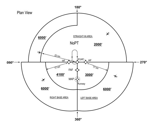
-
U.S. Government charts depict TAAs using icons located in the plan view outside the depiction of the actual approach procedure. (See FIG 5-4-6). Use of icons is necessary to avoid obscuring any portion of the “T” procedure (altitudes, courses, minimum altitudes, etc.). The icon for each TAA area will be located and oriented on the plan view with respect to the direction of arrival to the approach procedure, and will show all TAA minimum altitudes and sector/radius subdivisions. The IAF for each area of the TAA is included on the icon where it appears on the approach to help the pilot orient the icon to the approach procedure. The IAF name and the distance of the TAA area boundary from the IAF are included on the outside arc of the TAA area icon.
FIG 5-4-6
RNAV (GPS) Approach Chart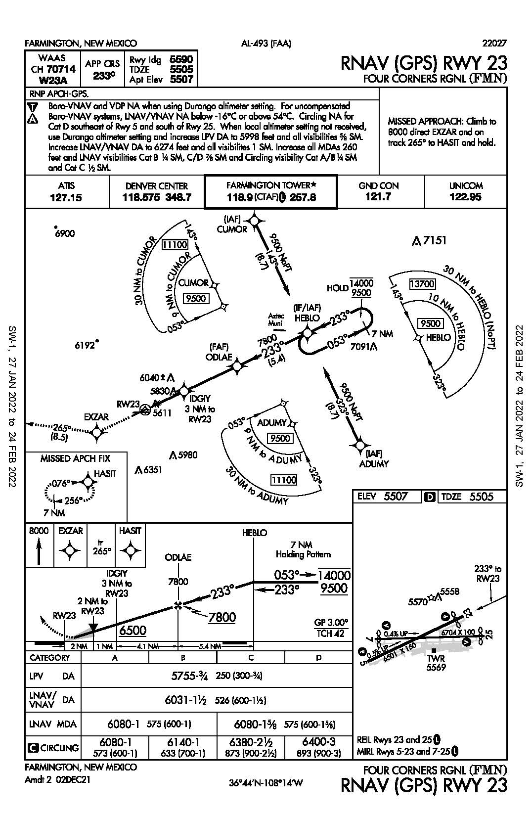
-
TAAs may be modified from the standard size and shape to accommodate operational or ATC requirements. Some areas may be eliminated, while the other areas are expanded. The “T” design may be modified by the procedure designers where required by terrain or ATC considerations. For instance, the “T” design may appear more like a regularly or irregularly shaped “Y,” upside down “L,” or an “I.”
-
FIG 5-4-7 depicts a TAA without a left base leg and right base leg. In this generalized example, pilots approaching on a bearing TO the IF/IAF from 271 clockwise to 089 are expected to execute a course reversal because the amount of turn required at the IF/IAF exceeds 90 degrees. The term “NoPT” will be annotated on the boundary of the TAA icon for the other portion of the TAA.
FIG 5-4-7
TAA with Left and Right Base Areas Eliminated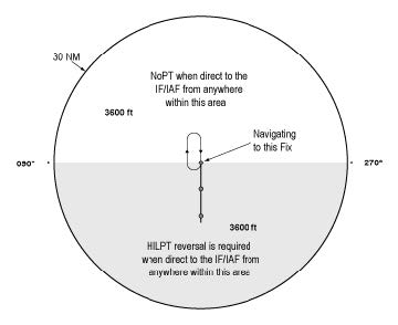
-
FIG 5-4-8 depicts another TAA modification that pilots may encounter. In this generalized example, the left base area and part of the straight-in area have been eliminated. Pilots operating within the TAA between 210 clockwise to 360 bearing TO the IF/IAF are expected to proceed direct to the IF/IAF and then execute the course reversal in order to properly align the aircraft for entry onto the intermediate segment or to avoid an excessive descent rate. Aircraft operating in areas from 001 clockwise to 090 bearing TO the IF/IAF are expected to proceed direct to the right base IAF and not execute course reversal maneuver. Aircraft cleared direct the IF/IAF by ATC in this sector will be expected to accomplish HILTP. Aircraft operating in areas 091 clockwise to 209 bearing TO the IF/IAF are expected to proceed direct to the IF/IAF and not execute the course reversal. These two areas are annotated “NoPT” at the TAA boundary of the icon in these areas when displayed on the approach chart's plan view.
FIG 5-4-8
TAA with Left Base and Part of Straight-In Area Eliminated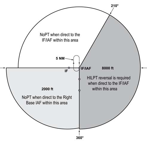
-
FIG 5-4-9 depicts a TAA with right base leg and part of the straight-in area eliminated.
FIG 5-4-9
TAA with Right Base Eliminated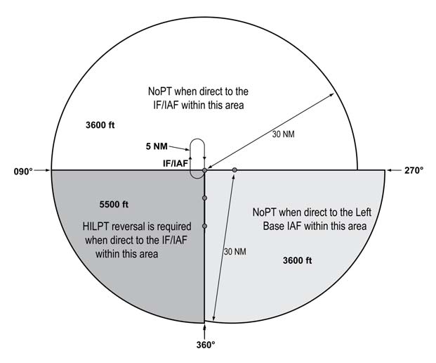
-
FIG 5-4-7 depicts a TAA without a left base leg and right base leg. In this generalized example, pilots approaching on a bearing TO the IF/IAF from 271 clockwise to 089 are expected to execute a course reversal because the amount of turn required at the IF/IAF exceeds 90 degrees. The term “NoPT” will be annotated on the boundary of the TAA icon for the other portion of the TAA.
-
When an airway does not cross the lateral TAA boundaries, a feeder route will be established from an airway fix or NAVAID to the TAA boundary to provide a transition from the en route structure to the appropriate IAF. Each feeder route will terminate at the TAA boundary and will be aligned along a path pointing to the associated IAF. Pilots should descend to the TAA altitude after crossing the TAA boundary and cleared for the approach by ATC. (See FIG 5-4-10).
FIG 5-4-10
Examples of a TAA with Feeders from an Airway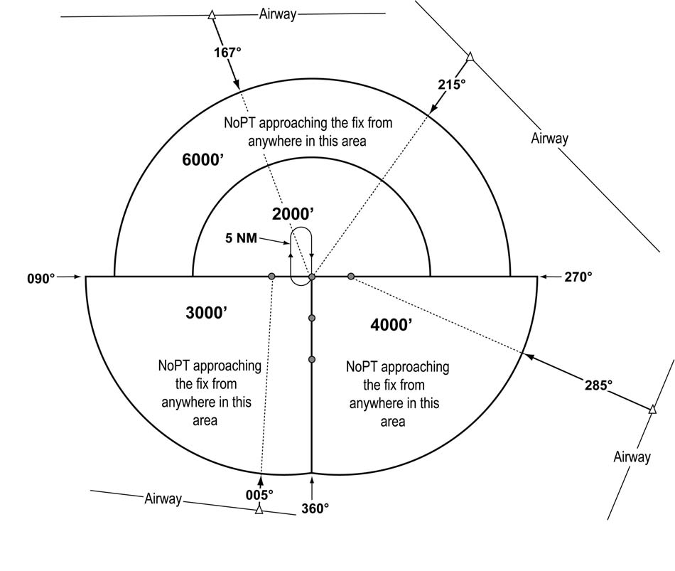
-
Each waypoint on the “T” is assigned a pronounceable 5-letter name, except the missed approach waypoint. These names are used for ATC communications, RNAV databases, and aeronautical navigation products. The missed approach waypoint is assigned a pronounceable name when it is not located at the runway threshold.
FIG 5-4-11
Minimum Vectoring Altitude Charts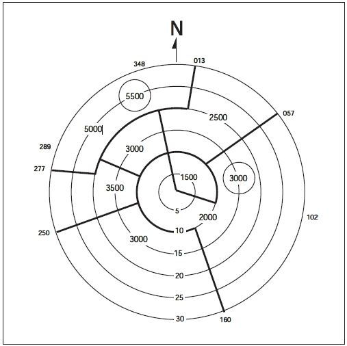
-
Minimum Vectoring Altitudes (MVAs) are established for use by ATC when radar ATC is exercised. MVA charts are prepared by air traffic facilities at locations where there are numerous different minimum IFR altitudes. Each MVA chart has sectors large enough to accommodate vectoring of aircraft within the sector at the MVA. Each sector boundary is at least 3 miles from the obstruction determining the MVA. To avoid a large sector with an excessively high MVA due to an isolated prominent obstruction, the obstruction may be enclosed in a buffer area whose boundaries are at least 3 miles from the obstruction. This is done to facilitate vectoring around the obstruction. (See FIG 5-4-11.)
-
The minimum vectoring altitude in each sector provides 1,000 feet above the highest obstacle in nonmountainous areas and 2,000 feet above the highest obstacle in designated mountainous areas. Where lower MVAs are required in designated mountainous areas to achieve compatibility with terminal routes or to permit vectoring to an IAP, 1,000 feet of obstacle clearance may be authorized with the use of ATC surveillance. The minimum vectoring altitude will provide at least 300 feet above the floor of controlled airspace.
NOTE-
OROCA is a published altitude which provides 1,000 feet of terrain and obstruction clearance in the U.S. (2,000 feet of clearance in designated mountainous areas). These altitudes are not assessed for NAVAID signal coverage, air traffic control surveillance, or communications coverage, and are published for general situational awareness, flight planning and in-flight contingency use.
- Because of differences in the areas considered for MVA, and those applied to other minimum altitudes, and the ability to isolate specific obstacles, some MVAs may be lower than the nonradar Minimum En Route Altitudes (MEAs), Minimum Obstruction Clearance Altitudes (MOCAs) or other minimum altitudes depicted on charts for a given location. While being radar vectored, IFR altitude assignments by ATC will be at or above MVA.
- The MVA/MIA may be lower than the TAA minimum altitude. If ATC has assigned an altitude to an aircraft that is below the TAA minimum altitude, the aircraft will either be assigned an altitude to maintain until established on a segment of a published route or instrument approach procedure, or climbed to the TAA altitude.
-
The minimum vectoring altitude in each sector provides 1,000 feet above the highest obstacle in nonmountainous areas and 2,000 feet above the highest obstacle in designated mountainous areas. Where lower MVAs are required in designated mountainous areas to achieve compatibility with terminal routes or to permit vectoring to an IAP, 1,000 feet of obstacle clearance may be authorized with the use of ATC surveillance. The minimum vectoring altitude will provide at least 300 feet above the floor of controlled airspace.
-
Circling. Circling minimums charted on an RNAV (GPS) approach chart may be lower than the LNAV/VNAV line of minima, but never lower than the LNAV line of minima (straight-in approach). Pilots may safely perform the circling maneuver at the circling published line of minima if the approach and circling maneuver is properly performed according to aircraft category and operational limitations.
FIG 5-4-12
Example of LNAV and Circling Minima Lower Than LNAV/VNAV DA. Harrisburg International RNAV (GPS) RWY 13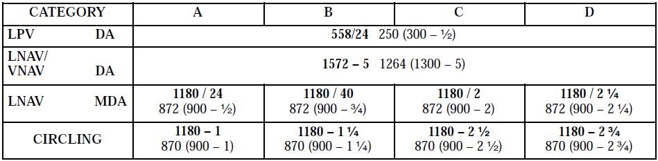
FIG 5-4-13
Explanation of LNAV and/or Circling Minima Lower than LNAV/VNAV DA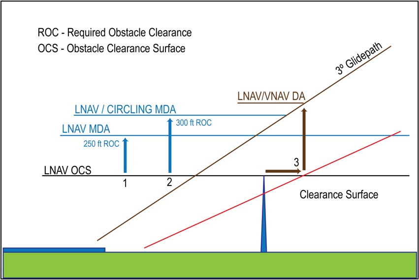
-
FIG 5-4-13 provides a visual representation of an obstacle evaluation and calculation of LNAV MDA, Circling MDA, LNAV/VNAV DA.
- No vertical guidance (LNAV). A line is drawn horizontal at obstacle height and 250 feet added for Required Obstacle Clearance (ROC). The controlling obstacle used to determine LNAV MDA can be different than the controlling obstacle used in determining ROC for circling MDA. Other factors may force a number larger than 250 ft to be added to the LNAV OCS. The number is rounded up to the next higher 20 foot increment.
- Circling MDA. The circling MDA will provide 300 foot obstacle clearance within the area considered for obstacle clearance and may be lower than the LNAV/VNAV DA, but never lower than the straight in LNAV MDA. This may occur when different controlling obstacles are used or when other controlling factors force the LNAV MDA to be higher than 250 feet above the LNAV OCS. In FIG 5-4-12, the required obstacle clearance for both the LNAV and Circle resulted in the same MDA, but lower than the LNAV/VNAV DA. FIG 5-4-13 provides an illustration of this type of situation.
- Vertical guidance (LNAV/VNAV). A line is drawn horizontal at obstacle height until reaching the obstacle clearance surface (OCS). At the OCS, a vertical line is drawn until reaching the glide path. This is the DA for the approach. This method places the offending obstacle in front of the LNAV/VNAV DA so it can be seen and avoided. In some situations, this may result in the LNAV/VNAV DA being higher than the LNAV and/or Circling MDA.
-
The Visual Descent Point (VDP), identified by the symbol (V), is a defined point on the final approach course of a nonprecision straight-in approach procedure from which a stabilized visual descent from the MDA to the runway touchdown point may be commenced. The pilot should not descend below the MDA prior to reaching the VDP. The VDP will be identified by DME or RNAV along-track distance to the MAP. The VDP distance is based on the lowest MDA published on the IAP and harmonized with the angle of the visual glide slope indicator (VGSI) (if installed) or the procedure VDA (if no VGSI is installed). A VDP may not be published under certain circumstances which may result in a destabilized descent between the MDA and the runway touchdown point. Such circumstances include an obstacle penetrating the visual surface between the MDA and runway threshold, lack of distance measuring capability, or the procedure design prevents a VDP to be identified.
- VGSI systems may be used as a visual aid to the pilot to determine if the aircraft is in a position to make a stabilized descent from the MDA. When the visibility is close to minimums, the VGSI may not be visible at the VDP due to its location beyond the MAP.
- Pilots not equipped to receive the VDP should fly the approach procedure as though no VDP had been provided.
- On a straight-in nonprecision IAP, descent below the MDA between the VDP and the MAP may be inadvisable or impossible. Aircraft speed, height above the runway, descent rate, amount of turn, and runway length are some of the factors which must be considered by the pilot to determine if a safe descent and landing can be accomplished.
-
A visual segment obstruction evaluation is accomplished during procedure design on all IAPs. Obstacles (both lighted and unlighted) are allowed to penetrate the visual segment obstacle identification surfaces. Identified obstacle penetrations may cause restrictions to instrument approach operations which may include an increased approach visibility requirement, not publishing a VDP, and/or prohibiting night instrument operations to the runway. There is no implicit obstacle protection from the MDA/DA to the touchdown point. Accordingly, it is the responsibility of the pilot to visually acquire and avoid obstacles below the MDA/DA during transition to landing.
- Unlighted obstacle penetrations may result in prohibiting night instrument operations to the runway. A chart note will be published in the pilot briefing strip “Procedure NA at Night.”
- Use of a VGSI may be approved in lieu of obstruction lighting to restore night instrument operations to the runway. A chart note will be published in the pilot briefing strip “ Straight-in Rwy XX at Night, operational VGSI required, remain on or above VGSI glidepath until threshold.”
- The highest obstacle (man-made, terrain, or vegetation) will be charted on the planview of an IAP. Other obstacles may be charted in either the planview or the airport sketch based on distance from the runway and available chart space. The elevation of the charted obstacle will be shown to the nearest foot above mean sea level. Obstacles without a verified accuracy are indicated by a ± symbol following the elevation value.
-
Vertical Descent Angle (VDA). FAA policy is to publish a VDA/TCH on all nonprecision approaches except those published in conjunction with vertically guided minimums (i.e., ILS or LOC RWY XX) or no-FAF procedures without a step-down fix (i.e., on-airport VOR or NDB). A VDA does not guarantee obstacle protection below the MDA in the visual segment. The presence of a VDA does not change any nonprecision approach requirements.
-
Obstacles may penetrate the obstacle identification surface below the MDA in the visual segment of an IAP that has a published VDA/TCH. When the VDA/TCH is not authorized due to an obstacle penetration that would require a pilot to deviate from the VDA between MDA and touchdown, the VDA/TCH will be replaced with the note “Visual Segment- Obstacles” in the profile view of the IAP (See FIG 5-4-14). Accordingly, pilots are advised to carefully review approach procedures to identify where the optimum stabilized descent to landing can be initiated. Pilots that follow the previously published descent angle, provided by the RNAV system, below the MDA on procedures with this note may encounter obstacles in the visual segment. Pilots must visually avoid any obstacles below the MDA.
- VDA/TCH data is furnished by FAA on the official source document for publication on IAP charts and for coding in the navigation database unless, as noted previously, replaced by the note “Visual Segment - Obstacles.”
- Commercial chart providers and navigation systems may publish or calculate a VDA/TCH even when the FAA does not provide such data. Pilots are cautioned that they are responsible for obstacle avoidance in the visual segment regardless of the presence or absence of a VDA/TCH and associated navigation system advisory vertical guidance.
- The threshold crossing height (TCH) used to compute the descent angle is published with the VDA. The VDA and TCH information are charted on the profile view of the IAP following the fix (FAF/stepdown) used to compute the VDA. If no PA/APV IAP is established to the same runway, the VDA will be equal to or higher than the glide path angle of the VGSI installed on the same runway provided it is within instrument procedure criteria. A chart note will indicate if the VGSI is not coincident with the VDA. Pilots must be aware that the published VDA is for advisory information only and not to be considered instrument procedure derived vertical guidance. The VDA solely offers an aid to help pilots establish a continuous, stabilized descent during final approach.
-
Pilots may use the published angle and estimated/actual groundspeed to find a target rate of descent from the rate of descent table published in the back of the U.S. Terminal Procedures Publication. This rate of descent can be flown with the Vertical Velocity Indicator (VVI) in order to use the VDA as an aid to flying a stabilized descent. No special equipment is required.
FIG 5-4-14
Example of a Chart Note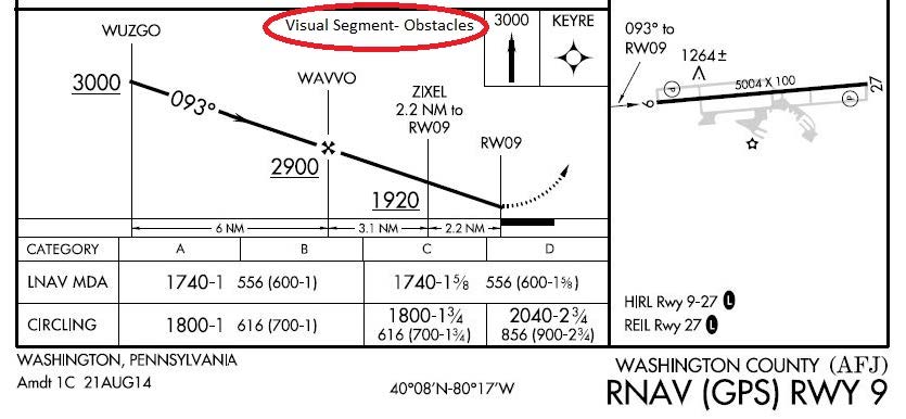
- A straight-in aligned procedure may be restricted to circling only minimums when an excessive descent gradient necessitates. The descent angle between the FAF/stepdown fix and the Circling MDA must not exceed the maximum descent angle allowed by TERPS criteria. A published VDA on these procedures does not imply that landing straight ahead is recommended or even possible. The descent rate based on the VDA may exceed the capabilities of the aircraft and the pilot must determine how to best maneuver the aircraft within the circling area in order to land safely.
-
Obstacles may penetrate the obstacle identification surface below the MDA in the visual segment of an IAP that has a published VDA/TCH. When the VDA/TCH is not authorized due to an obstacle penetration that would require a pilot to deviate from the VDA between MDA and touchdown, the VDA/TCH will be replaced with the note “Visual Segment- Obstacles” in the profile view of the IAP (See FIG 5-4-14). Accordingly, pilots are advised to carefully review approach procedures to identify where the optimum stabilized descent to landing can be initiated. Pilots that follow the previously published descent angle, provided by the RNAV system, below the MDA on procedures with this note may encounter obstacles in the visual segment. Pilots must visually avoid any obstacles below the MDA.
-
In isolated cases, an IAP may contain a published visual flight path. These procedures are annotated “Fly Visual to Airport” or “Fly Visual.” A dashed arrow indicating the visual flight path will be included in the profile and plan views with a defined flightpath or approximate heading and distance to the end of the runway.
- The depicted ground track or flightpath associated with the “Fly Visual to Airport” segment should be flown with flight instrumentation (when advisory lateral and vertical guidance is provided) and/or pilotage or dead reckoning navigation techniques. When executing the “Fly Visual to Airport” segment, the flight visibility must not be less than that prescribed in the IAP; the pilot must remain clear of clouds and proceed to the airport maintaining visual contact with the ground. Altitude on the visual flight path is at the discretion of the pilot, and recommended altitudes may be shown, but it is the responsibility of the pilot to visually acquire and avoid obstacles in the “Fly Visual to Airport” segment.
-
Missed approach obstacle clearance is assured only if the missed approach is commenced at or above the MDA/DA and flown from the published MAP. Before initiating an IAP that contains a “Fly Visual to Airport” segment, the pilot should have preplanned climb out options based on aircraft performance and terrain features. Obstacle clearance is the responsibility of the pilot when the missed approach maneuver is initiated below the MDA/DA or when the approach is continued beyond the MAP.
NOTE-
The FAA Administrator retains the authority to approve instrument approach procedures where the pilot, on arrival at the MDA/DA on the prescribed flightpath, may not necessarily have one of the visual references specified in 14 CFR § 91.175 and related rules. While it is not a function of procedure design to ensure compliance with § 91.175, the pilot is always required to assess prevailing flight visibility against the published minima. When published on the procedure, the annotation “Fly Visual to Airport” provides specific relief only from §91.175 (c)(3)(i) through (x) requirements that the pilot have distinctly visible and identifiable visual references prior to descent below MDA/DA.
-
Area Navigation (RNAV) Instrument Approach Charts. Reliance on RNAV systems for instrument operations is becoming more commonplace as new systems such as GPS and augmented GPS such as the Wide Area Augmentation System (WAAS) are developed and deployed. In order to support full integration of RNAV procedures into the National Airspace System (NAS), the FAA developed a new charting format for IAPs (See FIG 5-4-6). This format avoids unnecessary duplication and proliferation of instrument approach charts. The original stand alone GPS charts, titled simply “GPS,” are being converted to the newer format as the procedures are revised. One reason for the revision is the addition of WAAS based minima to the approach chart. The reformatted approach chart is titled “RNAV (GPS) RWY XX.” Up to four lines of minima are included on these charts. Ground Based Augmentation System (GBAS) Landing System (GLS) was a placeholder for future WAAS and LAAS minima, and the minima was always listed as N/A. The GLS minima line has now been replaced by the WAAS LPV (Localizer Performance with Vertical Guidance) minima on most RNAV (GPS) charts. LNAV/VNAV (lateral navigation/vertical navigation) was added to support both WAAS electronic vertical guidance and Barometric VNAV. LPV and LNAV/VNAV are both APV procedures as described in paragraph 5-4-5a7. The original GPS minima, titled “S-XX,” for straight in runway XX, is retitled LNAV (lateral navigation). Circling minima may also be published. A new type of nonprecision WAAS minima will also be published on this chart and titled LP (localizer performance). LP will be published in locations where vertically guided minima cannot be provided due to terrain and obstacles and therefore, no LPV or LNAV/VNAV minima will be published. GBAS procedures are published on a separate chart and the GLS minima line is to be used only for GBAS. ATC clearance for the RNAV procedure authorizes a properly certified pilot to utilize any minimums for which the aircraft is certified (for example, a WAAS equipped aircraft utilizes the LPV or LP minima but a GPS only aircraft may not). The RNAV chart includes information formatted for quick reference by the pilot or flight crew at the top of the chart. This portion of the chart, developed based on a study by the Department of Transportation, Volpe National Transportation System Center, is commonly referred to as the pilot briefing.
-
The minima lines are:
- GLS. “GLS” is the acronym for GBAS Landing System. The U.S. version of GBAS has traditionally been referred to as LAAS. The worldwide community has adopted GBAS as the official term for this type of navigation system. To coincide with international terminology, the FAA is also adopting the term GBAS to be consistent with the international community. This line was originally published as a placeholder for both WAAS and LAAS minima and marked as N/A since no minima was published. As the concepts for GBAS and WAAS procedure publication have evolved, GLS will now be used only for GBAS minima, which will be on a separate approach chart. Most RNAV(GPS) approach charts have had the GLS minima line replaced by a WAAS LPV line of minima.
- LPV. “LPV” is the acronym for localizer performance with vertical guidance. RNAV (GPS) approaches to LPV lines of minima take advantage of the improved accuracy of WAAS lateral and vertical guidance to provide an approach that is very similar to a Category I Instrument Landing System (ILS). The approach to LPV line of minima is designed for angular guidance with increasing sensitivity as the aircraft gets closer to the runway. The sensitivities are nearly identical to those of the ILS at similar distances. This was done intentionally to allow the skills required to proficiently fly an ILS to readily transfer to flying RNAV (GPS) approaches to the LPV line of minima. Just as with an ILS, the LPV has vertical guidance and is flown to a DA. Aircraft can fly this minima line with a statement in the Aircraft Flight Manual that the installed equipment supports LPV approaches. This includes Class 3 and 4 TSO-C146 GPS/WAAS equipment.
- LNAV/VNAV. LNAV/VNAV identifies APV minimums developed to accommodate an RNAV IAP with vertical guidance, usually provided by approach certified Baro-VNAV, but with lateral and vertical integrity limits larger than a precision approach or LPV. LNAV stands for Lateral Navigation; VNAV stands for Vertical Navigation. This minima line can be flown by aircraft with a statement in the Aircraft Flight Manual that the installed equipment supports GPS approaches and has an approach-approved barometric VNAV, or if the aircraft has been demonstrated to support LNAV/VNAV approaches. This includes Class 2, 3 and 4 TSO-C146 GPS/WAAS equipment. Aircraft using LNAV/VNAV minimums will descend to landing via an internally generated descent path based on satellite or other approach approved VNAV systems. Since electronic vertical guidance is provided, the minima will be published as a DA. Other navigation systems may be specifically authorized to use this line of minima. (See Section A, Terms/Landing Minima Data, of the U.S. Terminal Procedures books.)
- LP. “LP” is the acronym for localizer performance. Approaches to LP lines of minima take advantage of the improved accuracy of WAAS to provide approaches, with lateral guidance and angular guidance. Angular guidance does not refer to a glideslope angle but rather to the increased lateral sensitivity as the aircraft gets closer to the runway, similar to localizer approaches. However, the LP line of minima is a Minimum Descent Altitude (MDA) rather than a DA (H). Procedures with LP lines of minima will not be published with another approach that contains approved vertical guidance (LNAV/VNAV or LPV). It is possible to have LP and LNAV published on the same approach chart but LP will only be published if it provides lower minima than an LNAV line of minima. LP is not a fail-down mode for LPV. LP will only be published if terrain, obstructions, or some other reason prevent publishing a vertically guided procedure. WAAS avionics may provide GNSS-based advisory vertical guidance during an approach to an LP line of minima. Barometric altimeter information remains the primary altitude reference for complying with any altitude restrictions. WAAS equipment may not support LP, even if it supports LPV, if it was approved before TSO-C145b and TSO-C146b. Receivers approved under previous TSOs may require an upgrade by the manufacturer in order to be used to fly to LP minima. Receivers approved for LP must have a statement in the approved Flight Manual or Supplemental Flight Manual including LP as one of the approved approach types.
-
LNAV. This minima is for lateral navigation only, and the approach minimum altitude will be published as a minimum descent altitude (MDA). LNAV provides the same level of service as the present GPS stand alone approaches. LNAV minimums support the following navigation systems: WAAS, when the navigation solution will not support vertical navigation; and, GPS navigation systems which are presently authorized to conduct GPS approaches.
NOTE-
GPS receivers approved for approach operations in accordance with: AC 20-138, Airworthiness Approval of Positioning and Navigation Systems, qualify for this minima. WAAS navigation equipment must be approved in accordance with the requirements specified in TSO-C145() or TSO-C146() and installed in accordance with Advisory Circular AC 20-138.
-
Other systems may be authorized to utilize these approaches. See the description in Section A of the U.S. Terminal Procedures books for details. Operational approval must also be obtained for Baro-VNAV systems to operate to the LNAV/VNAV minimums. Baro-VNAV may not be authorized on some approaches due to other factors, such as no local altimeter source being available. Baro-VNAV is not authorized on LPV procedures. Pilots are directed to their local Flight Standards District Office (FSDO) for additional information.
NOTE-
RNAV and Baro-VNAV systems must have a manufacturer supplied electronic database which must include the waypoints, altitudes, and vertical data for the procedure to be flown. The system must be able to retrieve the procedure by name from the aircraft navigation database, not just as a manually entered series of waypoints.
-
ILS or RNAV (GPS) charts.
-
Some RNAV (GPS) charts will also contain an ILS line of minima to make use of the ILS precision final in conjunction with the RNAV GPS capabilities for the portions of the procedure prior to the final approach segment and for the missed approach. Obstacle clearance for the portions of the procedure other than the final approach segment is still based on GPS criteria.
NOTE-
Some GPS receiver installations inhibit GPS navigation whenever ANY ILS frequency is tuned. Pilots flying aircraft with receivers installed in this manner must wait until they are on the intermediate segment of the procedure prior to the PFAF (PFAF is the active waypoint) to tune the ILS frequency and must tune the ILS back to a VOR frequency in order to fly the GPS based missed approach.
-
Charting. There are charting differences between ILS, RNAV (GPS), and GLS approaches.
- The LAAS procedure is titled “GLS RWY XX” on the approach chart.
- The VDB provides information to the airborne receiver where the guidance is synthesized.
- The LAAS procedure is identified by a four alpha-numeric character field referred to as the RPI or approach ID and is similar to the IDENT feature of the ILS.
- The RPI is charted.
- Most RNAV(GPS) approach charts have had the GLS (NA) minima line replaced by an LPV line of minima.
- Since the concepts for LAAS and WAAS procedure publication have evolved, GLS will now be used only for LAAS minima, which will be on a separate approach chart.
-
Some RNAV (GPS) charts will also contain an ILS line of minima to make use of the ILS precision final in conjunction with the RNAV GPS capabilities for the portions of the procedure prior to the final approach segment and for the missed approach. Obstacle clearance for the portions of the procedure other than the final approach segment is still based on GPS criteria.
-
Required Navigation Performance (RNP).
- Pilots are advised to refer to the “TERMS/LANDING MINIMUMS DATA” (Section A) of the U.S. Government Terminal Procedures books for aircraft approach eligibility requirements by specific RNP level requirements.
- Some aircraft have RNP approval in their AFM without a GPS sensor. The lowest level of sensors that the FAA will support for RNP service is DME/DME. However, necessary DME signal may not be available at the airport of intended operations. For those locations having an RNAV chart published with LNAV/VNAV minimums, a procedure note may be provided such as “DME/DME RNP-0.3 NA.” This means that RNP aircraft dependent on DME/DME to achieve RNP-0.3 are not authorized to conduct this approach. Where DME facility availability is a factor, the note may read “DME/DME RNP-0.3 Authorized; ABC and XYZ Required.” This means that ABC and XYZ facilities have been determined by flight inspection to be required in the navigation solution to assure RNP-0.3. VOR/DME updating must not be used for approach procedures.
-
Chart Terminology.
- Decision Altitude (DA) replaces the familiar term Decision Height (DH). DA conforms to the international convention where altitudes relate to MSL and heights relate to AGL. DA will eventually be published for other types of instrument approach procedures with vertical guidance, as well. DA indicates to the pilot that the published descent profile is flown to the DA (MSL), where a missed approach will be initiated if visual references for landing are not established. Obstacle clearance is provided to allow a momentary descent below DA while transitioning from the final approach to the missed approach. The aircraft is expected to follow the missed instructions while continuing along the published final approach course to at least the published runway threshold waypoint or MAP (if not at the threshold) before executing any turns.
- Minimum Descent Altitude (MDA) has been in use for many years, and will continue to be used for the LNAV only and circling procedures.
- Threshold Crossing Height (TCH) has been traditionally used in “precision” approaches as the height of the glide slope above threshold. With publication of LNAV/VNAV minimums and RNAV descent angles, including graphically depicted descent profiles, TCH also applies to the height of the “descent angle,” or glidepath, at the threshold. Unless otherwise required for larger type aircraft which may be using the IAP, the typical TCH is 30 to 50 feet.
-
The MINIMA FORMAT will also change slightly.
- Each line of minima on the RNAV IAP is titled to reflect the level of service available; e.g., GLS, LPV, LNAV/VNAV, LP, and LNAV. CIRCLING minima will also be provided.
-
The minima title box indicates the nature of the minimum altitude for the IAP. For example:
- DA will be published next to the minima line title for minimums supporting vertical guidance such as for GLS, LPV or LNAV/VNAV.
- MDA will be published as the minima line on approaches with lateral guidance only, LNAV, or LP. Descent below the MDA must meet the conditions stated in 14 CFR section 91.175.
- Where two or more systems, such as LPV and LNAV/VNAV, share the same minima, each line of minima will be displayed separately.
-
Chart Symbology changed slightly to include:
-
Descent Profile. The published descent profile and a graphical depiction of the vertical path to the runway will be shown. Graphical depiction of the RNAV vertical guidance will differ from the traditional depiction of an ILS glide slope (feather) through the use of a shorter vertical track beginning at the decision altitude.
- It is FAA policy to design IAPs with minimum altitudes established at fixes/waypoints to achieve optimum stabilized (constant rate) descents within each procedure segment. This design can enhance the safety of the operations and contribute toward reduction in the occurrence of controlled flight into terrain (CFIT) accidents. Additionally, the National Transportation Safety Board (NTSB) recently emphasized that pilots could benefit from publication of the appropriate IAP descent angle for a stabilized descent on final approach. The RNAV IAP format includes the descent angle to the hundredth of a degree; e.g., 3.00 degrees. The angle will be provided in the graphically depicted descent profile.
- The stabilized approach may be performed by reference to vertical navigation information provided by WAAS or LNAV/VNAV systems; or for LNAV-only systems, by the pilot determining the appropriate aircraft attitude/groundspeed combination to attain a constant rate descent which best emulates the published angle. To aid the pilot, U.S. Government Terminal Procedures Publication charts publish an expanded Rate of Descent Table on the inside of the back hard cover for use in planning and executing precision descents under known or approximate groundspeed conditions.
- Visual Descent Point (VDP). A VDP will be published on most RNAV IAPs. VDPs apply only to aircraft utilizing LP or LNAV minima, not LPV or LNAV/VNAV minimums.
- Missed Approach Symbology. In order to make missed approach guidance more readily understood, a method has been developed to display missed approach guidance in the profile view through the use of quick reference icons. Due to limited space in the profile area, only four or fewer icons can be shown. However, the icons may not provide representation of the entire missed approach procedure. The entire set of textual missed approach instructions are provided at the top of the approach chart in the pilot briefing. (See FIG 5-4-6).
- Waypoints. All RNAV or GPS stand-alone IAPs are flown using data pertaining to the particular IAP obtained from an onboard database, including the sequence of all WPs used for the approach and missed approach, except that step down waypoints may not be included in some TSO-C129 receiver databases. Included in the database, in most receivers, is coding that informs the navigation system of which WPs are fly-over (FO) or fly-by (FB). The navigation system may provide guidance appropriately - including leading the turn prior to a fly-by WP; or causing overflight of a fly-over WP. Where the navigation system does not provide such guidance, the pilot must accomplish the turn lead or waypoint overflight manually. Chart symbology for the FB WP provides pilot awareness of expected actions. Refer to the legend of the U.S. Terminal Procedures books.
- TAAs are described in paragraph 5-4-5d, Terminal Arrival Area (TAA). When published, the RNAV chart depicts the TAA areas through the use of “icons” representing each TAA area associated with the RNAV procedure (See FIG 5-4-6). These icons are depicted in the plan view of the approach chart, generally arranged on the chart in accordance with their position relative to the aircraft's arrival from the en route structure. The WP, to which navigation is appropriate and expected within each specific TAA area, will be named and depicted on the associated TAA icon. Each depicted named WP is the IAF for arrivals from within that area. TAAs may not be used on all RNAV procedures because of airspace congestion or other reasons.
-
Published Temperature Limitations. There are currently two temperature limitations that may be published in the notes box of the middle briefing strip on an instrument approach procedure (IAP). The two published temperature limitations are:
- A temperature range limitation associated with the use of baro-VNAV that may be published on a United States PBN IAP titled RNAV (GPS) or RNAV (RNP); and/or
-
A Cold Temperature Airport (CTA) limitation designated by a snowflake ICON and temperature in Celsius (C) that is published on every IAP for the airfield.
REFERENCE-
AIM, Chapter 7, Section 3, Cold Temperature Barometric Altimeter Errors, Setting Procedures and Cold Temperature Airports (CTA).
- WAAS Channel Number/Approach ID. The WAAS Channel Number is an optional equipment capability that allows the use of a 5-digit number to select a specific final approach segment without using the menu method. The Approach ID is an airport unique 4-character combination for verifying the selection and extraction of the correct final approach segment information from the aircraft database. It is similar to the ILS ident, but displayed visually rather than aurally. The Approach ID consists of the letter W for WAAS, the runway number, and a letter other than L, C or R, which could be confused with Left, Center and Right, e.g., W35A. Approach IDs are assigned in the order that WAAS approaches are built to that runway number at that airport. The WAAS Channel Number and Approach ID are displayed in the upper left corner of the approach procedure pilot briefing.
-
At locations where outages of WAAS vertical guidance may occur daily due to initial system limitations, a negative W symbol (
 ) will be placed on RNAV (GPS) approach charts. Many of these outages will be very short in duration, but may result in the disruption of the vertical portion of the approach. The symbol indicates that NOTAMs or Air Traffic advisories are not provided for outages which occur in the WAAS LNAV/VNAV or LPV vertical service. Use LNAV or circling minima for flight planning at these locations, whether as a destination or alternate. For flight operations at these locations, when the WAAS avionics indicate that LNAV/VNAV or LPV service is available, then vertical guidance may be used to complete the approach using the displayed level of service. Should an outage occur during the procedure, reversion to LNAV minima may be required. As the WAAS coverage is expanded, the will be removed.
NOTE-
Properly trained and approved, as required, TSO-C145() and TSO-C146() equipped users (WAAS users) with and using approved baro-VNAV equipment may plan for LNAV/VNAV DA at an alternate airport. Specifically authorized WAAS users with and using approved baro-VNAV equipment may also plan for RNP 0.3 DA at the alternate airport as long as the pilot has verified RNP availability through an approved prediction program.
-
Descent Profile. The published descent profile and a graphical depiction of the vertical path to the runway will be shown. Graphical depiction of the RNAV vertical guidance will differ from the traditional depiction of an ILS glide slope (feather) through the use of a shorter vertical track beginning at the decision altitude.
-
The minima lines are:
-
14 CFR section 91.175(a), Instrument approaches to civil airports, requires the use of SIAPs prescribed for the airport in 14 CFR part 97 unless otherwise authorized by the Administrator (including ATC). If there are military procedures published at a civil airport, aircraft operating under 14 CFR part 91 must use the civil procedure(s). Civil procedures are defined with “FAA” in parenthesis; e.g., (FAA), at the top, center of the procedure chart. DoD procedures are defined using the abbreviation of the applicable military service in parenthesis; e.g., (USAF), (USN), (USA). 14 CFR section 91.175(g), Military airports, requires civil pilots flying into or out of military airports to comply with the IAPs and takeoff and landing minimums prescribed by the authority having jurisdiction at those airports. Unless an emergency exists, civil aircraft operating at military airports normally require advance authorization, commonly referred to as “Prior Permission Required” or “PPR.” Information on obtaining a PPR for a particular military airport can be found in the Chart Supplement.
-
Approach Clearance
- An aircraft which has been cleared to a holding fix and subsequently “cleared . . . approach” has not received new routing. Even though clearance for the approach may have been issued prior to the aircraft reaching the holding fix, ATC would expect the pilot to proceed via the holding fix (his/her last assigned route), and the feeder route associated with that fix (if a feeder route is published on the approach chart) to the initial approach fix (IAF) to commence the approach. WHEN CLEARED FOR THE APPROACH, THE PUBLISHED OFF AIRWAY (FEEDER) ROUTES THAT LEAD FROM THE EN ROUTE STRUCTURE TO THE IAF ARE PART OF THE APPROACH CLEARANCE.
- If a feeder route to an IAF begins at a fix located along the route of flight prior to reaching the holding fix, and clearance for an approach is issued, a pilot should commence the approach via the published feeder route; i.e., the aircraft would not be expected to overfly the feeder route and return to it. The pilot is expected to commence the approach in a similar manner at the IAF, if the IAF for the procedure is located along the route of flight to the holding fix.
- If a route of flight directly to the initial approach fix is desired, it should be so stated by the controller with phraseology to include the words “direct . . .,” “proceed direct” or a similar phrase which the pilot can interpret without question. When uncertain of the clearance, immediately query ATC as to what route of flight is desired.
- The name of an instrument approach, as published, is used to identify the approach, even though a component of the approach aid, such as the glideslope on an Instrument Landing System, is inoperative or unreliable. The controller will use the name of the approach as published, but must advise the aircraft at the time an approach clearance is issued that the inoperative or unreliable approach aid component is unusable, except when the title of the published approach procedures otherwise allows; for example, ILS Rwy 05 or LOC Rwy 05.
-
At times ATC may not specify a particular approach procedure in the clearance, but will state “CLEARED APPROACH.”
- This clearance indicates the pilot may execute any one of the authorized IAPs for that airport.
- The clearance may be issued in conjunction with the route to or over an IAF or feeder fix.
- This clearance does not constitute approval for the pilot to execute a contact approach or a visual approach to the airport or runway.
-
Except when being vectored to the final approach course, pilots cleared for an IAP are expected to execute the entire procedure commencing at an IAF or an associated feeder fix as described on the IAP chart. Pilots are not required to execute the entire procedure if:
- An appropriate new or revised ATC clearance is received, or
- The IFR flight plan is canceled.
-
STAR to Approach Connectivity. A STAR may terminate at a fix that is also the IAF or IF for an approach. When the arrival route instructions as published on the STAR state the pilot can expect the instrument approach from the STAR terminus fix or approach IAF or IF, pilots are expected to ensure that the RNAV system is loaded with the approach beginning at that IAF or IF so that the STAR and approach are connected. ATC will clear the aircraft for the instrument approach by stating the IAF fix/waypoint by name with the approach clearance. This procedure also applies to aircraft arriving to an airport via other air traffic services (ATS) routes.
EXAMPLE-
“At RDFSH, Cleared ILS Runway 27 Approach”
NOTE-
The fix “RDFSH” is the STAR terminus fix and an IAF for the ILS runway 27 approach at KIAH. Pilots are expected to ensure that the ILS Runway 27 approach is loaded in the RNAV system with the RDFSH IAF selected. Pilots are not to select vectors or vectors to final option when loading the ILS runway 27 approach.
-
The following applies to aircraft on radar vectors and/or cleared “direct to” in conjunction with an approach clearance:
- Maintain the last altitude assigned by ATC until the aircraft is established on a published segment of a transition route, or approach procedure segment, or other published route, for which a lower altitude is published on the chart. If already on an established route, or approach or arrival segment, you may descend to whatever minimum altitude is listed for that route or segment.
- Continue on the vector heading until intercepting the next published ground track applicable to the approach clearance.
- Once reaching the final approach fix via the published segments, the pilot may continue on approach to a landing.
- If proceeding to an IAF with a published course reversal (procedure turn or hold-in-lieu of PT pattern), except when cleared for a straight in approach by ATC, the pilot must execute the procedure turn/hold-in-lieu of PT, and complete the approach.
- If cleared to an IAF/IF via a NoPT route, or no procedure turn/hold-in-lieu of PT is published, continue with the published approach.
-
In addition to the above, RNAV aircraft may be issued a clearance direct to the IAF/IF at intercept angles not greater than 90 degrees for both conventional and RNAV instrument approaches. Controllers may issue a heading or a course direct to a fix between the IF and FAF at intercept angles not greater than 30 degrees for both conventional and RNAV instrument approaches. In all cases, controllers will assign altitudes that ensure obstacle clearance and will permit a normal descent to the FAF. When clearing aircraft direct to the IF, ATC will radar monitor the aircraft until the IF and will advise the pilot to expect clearance direct to the IF at least 5 miles from the fix. ATC must issue a straight-in approach clearance when clearing an aircraft direct to an IAF/IF with a procedure turn or hold-in-lieu of a procedure turn, and ATC does not want the aircraft to execute the course reversal.
NOTE-
Refer to 14 CFR 91.175 (i).
-
RNAV aircraft may be issued a clearance direct to the FAF that is also charted as an IAF, in which case the pilot is expected to execute the depicted procedure turn or hold-in-lieu of procedure turn. ATC will not issue a straight-in approach clearance. If the pilot desires a straight-in approach, they must request vectors to the final approach course outside of the FAF or fly a published “NoPT” route. When visual approaches are in use, ATC may clear an aircraft direct to the FAF.
NOTE-
- In anticipation of a clearance by ATC to any fix published on an instrument approach procedure, pilots of RNAV aircraft are advised to select an appropriate IAF or feeder fix when loading an instrument approach procedure into the RNAV system.
- Selection of “Vectors-to-Final” or “Vectors” option for an instrument approach may prevent approach fixes located outside of the FAF from being loaded into an RNAV system. Therefore, the selection of these options is discouraged due to increased workload for pilots to reprogram the navigation system.
-
Arrival Holding. Some approach charts have an arrival holding pattern depicted at an IAF or at a feeder fix located along an airway. The arrival hold is depicted using a “thin line” since it is not always a mandatory part of the instrument procedure.
- Arrival holding is charted where holding is frequently required prior to starting the approach procedure so that detailed holding instructions are not required. The arrival holding pattern is not authorized unless assigned by ATC. Holding at the same fix may also be depicted on the en route chart.
-
Arrival holding is also charted where it is necessary to use a holding pattern to align the aircraft for procedure entry from an airway due to turn angle limitations imposed by procedure design standards. When the turn angle from an airway into the approach procedure exceeds the permissible limits, an arrival holding pattern may be published along with a note on the procedure specifying the fix, the airway, and arrival direction where use of the arrival hold is required for procedure entry. Unlike a hold-in-lieu of procedure turn, use of the arrival holding pattern is not authorized until assigned by ATC. If ATC does not assign the arrival hold before reaching the holding fix, the pilot should request the hold for procedure entry. Once established on the inbound holding course and an approach clearance has been received, the published procedure can commence. Alternatively, if using the holding pattern for procedure entry is not desired, the pilot may ask ATC for maneuvering airspace to align the aircraft with the feeder course.
EXAMPLE-
Planview Chart Note: “Proc NA via V343 northeast bound without holding at JOXIT. ATC CLNC REQD.”
-
An RF leg is defined as a constant radius circular path around a defined turn center that starts and terminates at a fix. An RF leg may be published as part of a procedure. Since not all aircraft have the capability to fly these leg types, pilots are responsible for knowing if they can conduct an RNAV approach with an RF leg. Requirements for RF legs will be indicated on the approach chart in the notes section or at the applicable initial approach fix. Controllers will clear RNAV-equipped aircraft for instrument approach procedures containing RF legs:
- Via published transitions, or
- In accordance with paragraph e6 above, and
-
ATC will not clear aircraft direct to any waypoint beginning or within an RF leg, and will not assign fix/waypoint crossing speeds in excess of charted speed restrictions.
EXAMPLE-
Controllers will not clear aircraft direct to THIRD because that waypoint begins the RF leg, and aircraft cannot be vectored or cleared to TURNN or vectored to intercept the approach segment at any point between THIRD and FORTH because this is the RF leg. (See FIG 5-4-15.)
- When necessary to cancel a previously issued approach clearance, the controller will advise the pilot “Cancel Approach Clearance” followed by any additional instructions when applicable.
-
Instrument Approach Procedures
- Aircraft approach category means a grouping of aircraft based on a speed of VREF at the maximum certified landing weight, if specified, or if VREF is not specified, 1.3VSO at the maximum certified landing weight. VREF, VSO, and the maximum certified landing weight are those values as established for the aircraft by the certification authority of the country of registry. A pilot must maneuver the aircraft within the circling approach protected area (see FIG 5-4-27) to achieve the obstacle and terrain clearances provided by procedure design criteria.
- In addition to pilot techniques for maneuvering, one acceptable method to reduce the risk of flying out of the circling approach protected area is to use either the minima corresponding to the category determined during certification or minima associated with a higher category. Helicopters may use Category A minima. If it is necessary to operate at a speed in excess of the upper limit of the speed range for an aircraft's category, the minimums for the higher category should be used. This may occur with certain aircraft types operating in heavy/gusty wind, icing, or non-normal conditions. For example, an airplane which fits into Category B, but is circling to land at a speed of 145 knots, should use the approach Category D minimums. As an additional example, a Category A airplane (or helicopter) which is operating at 130 knots on a straight-in approach should use the approach Category C minimums.
-
A pilot who chooses an alternative method when it is necessary to maneuver at a speed that exceeds the category speed limit (for example, where higher category minimums are not published) should consider the following factors that can significantly affect the actual ground track flown:
- Bank angle. For example, at 165 knots groundspeed, the radius of turn increases from 4,194 feet using 30 degrees of bank to 6,654 feet when using 20 degrees of bank. When using a shallower bank angle, it may be necessary to modify the flightpath or indicated airspeed to remain within the circling approach protected area. Pilots should be aware that excessive bank angle can lead to a loss of aircraft control.
- Indicated airspeed. Procedure design criteria typically utilize the highest speed for a particular category. If a pilot chooses to operate at a higher speed, other factors should be modified to ensure that the aircraft remains within the circling approach protected area.
- Wind speed and direction. For example, it is not uncommon to maneuver the aircraft to a downwind leg where the groundspeed will be considerably higher than the indicated airspeed. Pilots must carefully plan the initiation of all turns to ensure that the aircraft remains within the circling approach protected area.
- Pilot technique. Pilots frequently have many options with regard to flightpath when conducting circling approaches. Sound planning and judgment are vital to proper execution. The lateral and vertical path to be flown should be carefully considered using current weather and terrain information to ensure that the aircraft remains within the circling approach protected area.
- It is important to remember that 14 CFR section 91.175(c) requires that “where a DA/DH or MDA is applicable, no pilot may operate an aircraft below the authorized MDA or continue an approach below the authorized DA/DH unless the aircraft is continuously in a position from which a descent to a landing on the intended runway can be made at a normal rate of descent using normal maneuvers, and for operations conducted under part 121 or part 135 unless that descent rate will allow touchdown to occur within the touchdown zone of the runway of intended landing.”
-
See the following category limits:
- Category A: Speed less than 91 knots.
- Category B: Speed 91 knots or more but less than 121 knots.
- Category C: Speed 121 knots or more but less than 141 knots.
- Category D: Speed 141 knots or more but less than 166 knots.
-
Category E: Speed 166 knots or more.
NOTE-
VREF in the above definition refers to the speed used in establishing the approved landing distance under the airworthiness regulations constituting the type certification basis of the airplane, regardless of whether that speed for a particular airplane is 1.3 VSO, 1.23 VSR, or some higher speed required for airplane controllability. This speed, at the maximum certificated landing weight, determines the lowest applicable approach category for all approaches regardless of actual landing weight.
-
When operating on an unpublished route or while being radar vectored, the pilot, when an approach clearance is received, must, in addition to complying with the minimum altitudes for IFR operations (14 CFR section 91.177), maintain the last assigned altitude unless a different altitude is assigned by ATC, or until the aircraft is established on a segment of a published route or IAP. After the aircraft is so established, published altitudes apply to descent within each succeeding route or approach segment unless a different altitude is assigned by ATC. Notwithstanding this pilot responsibility, for aircraft operating on unpublished routes or while being radar vectored, ATC will, except when conducting a radar approach, issue an IFR approach clearance only after the aircraft is established on a segment of a published route or IAP, or assign an altitude to maintain until the aircraft is established on a segment of a published route or instrument approach procedure. For this purpose, the procedure turn of a published IAP must not be considered a segment of that IAP until the aircraft reaches the initial fix or navigation facility upon which the procedure turn is predicated.
EXAMPLE-
Cross Redding VOR at or above five thousand, cleared VOR runway three four approach.
or
Five miles from outer marker, turn right heading three three zero, maintain two thousand until established on the localizer, cleared ILS runway three six approach.NOTE-
- The altitude assigned will assure IFR obstruction clearance from the point at which the approach clearance is issued until established on a segment of a published route or IAP. If uncertain of the meaning of the clearance, immediately request clarification from ATC.
- An aircraft is not established on an approach while below published approach altitudes. If the MVA/MIA allows, and ATC assigns an altitude below an IF or IAF altitude, the pilot will be issued an altitude to maintain until past a point that the aircraft is established on the approach.
-
Several IAPs, using various navigation and approach aids may be authorized for an airport. ATC may advise that a particular approach procedure is being used, primarily to expedite traffic. If issued a clearance that specifies a particular approach procedure, notify ATC immediately if a different one is desired. In this event it may be necessary for ATC to withhold clearance for the different approach until such time as traffic conditions permit. However, a pilot involved in an emergency situation will be given priority. If the pilot is not familiar with the specific approach procedure, ATC should be advised and they will provide detailed information on the execution of the procedure.
REFERENCE-
AIM, Para 5-4-4, Advance Information on Instrument Approach.
- The name of an instrument approach, as published, is used to identify the approach, even though a component of the approach aid, such as the glideslope on an Instrument Landing System, is inoperative or unreliable. The controller will use the name of the approach as published, but must advise the aircraft at the time an approach clearance is issued that the inoperative or unreliable approach aid component is unusable, except when the title of the published approach procedures otherwise allows, for example, ILS or LOC.
- Pilots planning flights to locations which are private airfields or which have instrument approach procedures based on private navigation aids should obtain approval from the owner. In addition, the pilot must be authorized by the FAA to fly special instrument approach procedures associated with private navigation aids (see paragraph 5-4-8). Owners of navigation aids that are not for public use may elect to turn off the signal for whatever reason they may have; for example, maintenance, energy conservation, etc. Air traffic controllers are not required to question pilots to determine if they have permission to land at a private airfield or to use procedures based on privately owned navigation aids, and they may not know the status of the navigation aid. Controllers presume a pilot has obtained approval from the owner and the FAA for use of special instrument approach procedures and is aware of any details of the procedure if an IFR flight plan was filed to that airport.
- Pilots should not rely on radar to identify a fix unless the fix is indicated as “RADAR” on the IAP. Pilots may request radar identification of an OM, but the controller may not be able to provide the service due either to workload or not having the fix on the video map.
-
If a missed approach is required, advise ATC and include the reason (unless initiated by ATC). Comply with the missed approach instructions for the instrument approach procedure being executed, unless otherwise directed by ATC.
REFERENCE-
AIM, Para 5-4-21, Missed Approach.
AIM, Para 5-5-5, Missed Approach.
-
Special Instrument Approach Procedures
Instrument Approach Procedure (IAP) charts reflect the criteria associated with the U.S. Standard for Terminal Instrument [Approach] Procedures (TERP), which prescribes standardized methods for use in developing IAPs. Standard IAPs are published in the Federal Register (FR) in accordance with Title 14 of the Code of Federal Regulations, part 97, and are available for use by appropriately qualified pilots operating properly equipped and airworthy aircraft in accordance with operating rules and procedures acceptable to the FAA. Special IAPs are also developed using TERPS but are not given public notice in the FR. The FAA authorizes only certain individual pilots and/or pilots in individual organizations to use special IAPs, and may require additional crew training and/or aircraft equipment or performance, and may also require the use of landing aids, communications, or weather services not available for public use. Additionally, IAPs that service private use airports or heliports are generally special IAPs. FDC NOTAMs for Specials, FDC T-NOTAMs, may also be used to promulgate safety-of-flight information relating to Specials provided the location has a valid landing area identifier and is serviced by the United States NOTAM system. Pilots may access NOTAMs online or through an FAA Flight Service Station (FSS). FSS specialists will not automatically provide NOTAM information to pilots for special IAPs during telephone pre-flight briefings. Pilots who are authorized by the FAA to use special IAPs must specifically request FDC NOTAM information for the particular special IAP they plan to use.
-
Procedure Turn and Hold-in-lieu of Procedure Turn
-
A procedure turn is the maneuver prescribed when it is necessary to reverse direction to establish the aircraft inbound on an intermediate or final approach course. The procedure turn or hold-in-lieu-of-PT is a required maneuver when it is depicted on the approach chart, unless cleared by ATC for a straight-in approach. Additionally, the procedure turn or hold-in-lieu-of-PT is not permitted when the symbol “No PT” is depicted on the initial segment being used, when a RADAR VECTOR to the final approach course is provided, or when conducting a timed approach from a holding fix. The altitude prescribed for the procedure turn is a minimum altitude until the aircraft is established on the inbound course. The maneuver must be completed within the distance specified in the profile view. For a hold-in-lieu-of-PT, the holding pattern direction must be flown as depicted and the specified leg length/timing must not be exceeded.
NOTE-
The pilot may elect to use the procedure turn or hold-in-lieu-of-PT when it is not required by the procedure, but must first receive an amended clearance from ATC. If the pilot is uncertain whether the ATC clearance intends for a procedure turn to be conducted or to allow for a straight-in approach, the pilot must immediately request clarification from ATC (14 CFR section 91.123).
- On U.S. Government charts, a barbed arrow indicates the maneuvering side of the outbound course on which the procedure turn is made. Headings are provided for course reversal using the 45 degree type procedure turn. However, the point at which the turn may be commenced and the type and rate of turn is left to the discretion of the pilot (limited by the charted remain within xx NM distance). Some of the options are the 45 degree procedure turn, the racetrack pattern, the teardrop procedure turn, or the 80 degree ↔ 260 degree course reversal. Racetrack entries should be conducted on the maneuvering side where the majority of protected airspace resides. If an entry places the pilot on the non-maneuvering side of the PT, correction to intercept the outbound course ensures remaining within protected airspace. Some procedure turns are specified by procedural track. These turns must be flown exactly as depicted.
-
Descent to the procedure turn (PT) completion altitude from the PT fix altitude (when one has been published or assigned by ATC) must not begin until crossing over the PT fix or abeam and proceeding outbound. Some procedures contain a note in the chart profile view that says “Maintain (altitude) or above until established outbound for procedure turn” (See FIG 5-4-16). Newer procedures will simply depict an “at or above” altitude at the PT fix without a chart note (See FIG 5-4-17). Both are there to ensure required obstacle clearance is provided in the procedure turn entry zone (See FIG 5-4-18). Absence of a chart note or specified minimum altitude adjacent to the PT fix is an indication that descent to the procedure turn altitude can commence immediately upon crossing over the PT fix, regardless of the direction of flight. This is because the minimum altitudes in the PT entry zone and the PT maneuvering zone are the same.
FIG 5-4-15
Example of an RNAV Approach with RF Leg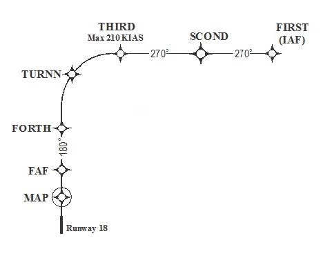
FIG 5-4-16
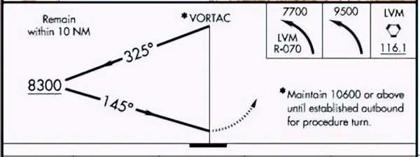
FIG 5-4-17
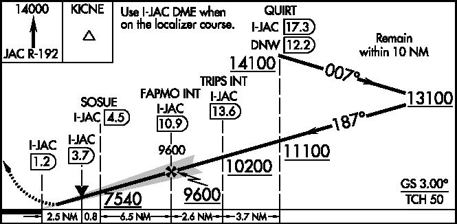
FIG 5-4-18
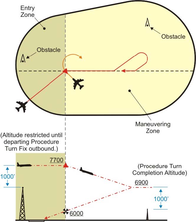
- When the approach procedure involves a procedure turn, a maximum speed of not greater than 200 knots (IAS) should be observed from first overheading the course reversal IAF through the procedure turn maneuver to ensure containment within the obstruction clearance area. Pilots should begin the outbound turn immediately after passing the procedure turn fix. The procedure turn maneuver must be executed within the distance specified in the profile view. The normal procedure turn distance is 10 miles. This may be reduced to a minimum of 5 miles where only Category A or helicopter aircraft are to be operated or increased to as much as 15 miles to accommodate high performance aircraft.
- A teardrop procedure or penetration turn may be specified in some procedures for a required course reversal. The teardrop procedure consists of departure from an initial approach fix on an outbound course followed by a turn toward and intercepting the inbound course at or prior to the intermediate fix or point. Its purpose is to permit an aircraft to reverse direction and lose considerable altitude within reasonably limited airspace. Where no fix is available to mark the beginning of the intermediate segment, it must be assumed to commence at a point 10 miles prior to the final approach fix. When the facility is located on the airport, an aircraft is considered to be on final approach upon completion of the penetration turn. However, the final approach segment begins on the final approach course 10 miles from the facility.
- A holding pattern in lieu of procedure turn may be specified for course reversal in some procedures. In such cases, the holding pattern is established over an intermediate fix or a final approach fix. The holding pattern distance or time specified in the profile view must be observed. For a hold-in-lieu-of-PT, the holding pattern direction must be flown as depicted and the specified leg length/timing must not be exceeded. Maximum holding airspeed limitations as set forth for all holding patterns apply. The holding pattern maneuver is completed when the aircraft is established on the inbound course after executing the appropriate entry. If cleared for the approach prior to returning to the holding fix, and the aircraft is at the prescribed altitude, additional circuits of the holding pattern are not necessary nor expected by ATC. If pilots elect to make additional circuits to lose excessive altitude or to become better established on course, it is their responsibility to so advise ATC upon receipt of their approach clearance.
- A procedure turn is not required when an approach can be made directly from a specified intermediate fix to the final approach fix. In such cases, the term “NoPT” is used with the appropriate course and altitude to denote that the procedure turn is not required. If a procedure turn is desired, and when cleared to do so by ATC, descent below the procedure turn altitude should not be made until the aircraft is established on the inbound course, since some NoPT altitudes may be lower than the procedure turn altitudes.
-
Limitations on Procedure Turns
- In the case of a radar initial approach to a final approach fix or position, or a timed approach from a holding fix, or where the procedure specifies NoPT, no pilot may make a procedure turn unless, when final approach clearance is received, the pilot so advises ATC and a clearance is received to execute a procedure turn.
- When a teardrop procedure turn is depicted and a course reversal is required, this type turn must be executed.
-
When a holding pattern replaces a procedure turn, the holding pattern must be followed, except when RADAR VECTORING is provided or when NoPT is shown on the approach course. The recommended entry procedures will ensure the aircraft remains within the holding pattern's protected airspace. As in the procedure turn, the descent from the minimum holding pattern altitude to the final approach fix altitude (when lower) may not commence until the aircraft is established on the inbound course. Where a holding pattern is established in-lieu-of a procedure turn, the maximum holding pattern airspeeds apply.
REFERENCE-
AIM, Para 5-3-8j2, Holding.
- The absence of the procedure turn barb in the plan view indicates that a procedure turn is not authorized for that procedure.
-
A procedure turn is the maneuver prescribed when it is necessary to reverse direction to establish the aircraft inbound on an intermediate or final approach course. The procedure turn or hold-in-lieu-of-PT is a required maneuver when it is depicted on the approach chart, unless cleared by ATC for a straight-in approach. Additionally, the procedure turn or hold-in-lieu-of-PT is not permitted when the symbol “No PT” is depicted on the initial segment being used, when a RADAR VECTOR to the final approach course is provided, or when conducting a timed approach from a holding fix. The altitude prescribed for the procedure turn is a minimum altitude until the aircraft is established on the inbound course. The maneuver must be completed within the distance specified in the profile view. For a hold-in-lieu-of-PT, the holding pattern direction must be flown as depicted and the specified leg length/timing must not be exceeded.
-
Timed Approaches from a Holding Fix
-
TIMED APPROACHES may be conducted when the following conditions are met:
- A control tower is in operation at the airport where the approaches are conducted.
- Direct communications are maintained between the pilot and the center or approach controller until the pilot is instructed to contact the tower.
- If more than one missed approach procedure is available, none require a course reversal.
-
If only one missed approach procedure is available, the following conditions are met:
- Course reversal is not required; and,
- Reported ceiling and visibility are equal to or greater than the highest prescribed circling minimums for the IAP.
- When cleared for the approach, pilots must not execute a procedure turn. (14 CFR section 91.175.)
- Although the controller will not specifically state that “timed approaches are in use,” the assigning of a time to depart the final approach fix inbound (nonprecision approach) or the outer marker or fix used in lieu of the outer marker inbound (precision approach) is indicative that timed approach procedures are being utilized, or in lieu of holding, the controller may use radar vectors to the Final Approach Course to establish a mileage interval between aircraft that will ensure the appropriate time sequence between the final approach fix/outer marker or fix used in lieu of the outer marker and the airport.
-
Each pilot in an approach sequence will be given advance notice as to the time they should leave the holding point on approach to the airport. When a time to leave the holding point has been received, the pilot should adjust the flight path to leave the fix as closely as possible to the designated time. (See FIG 5-4-19.)
FIG 5-4-19
Timed Approaches from a Holding Fix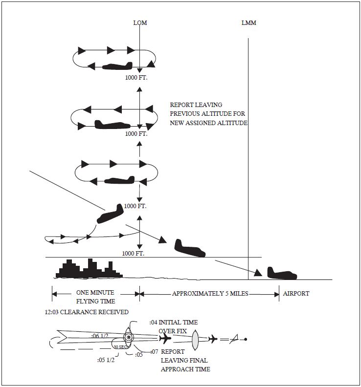
EXAMPLE-
At 12:03 local time, in the example shown, a pilot holding, receives instructions to leave the fix inbound at 12:07. These instructions are received just as the pilot has completed turn at the outbound end of the holding pattern and is proceeding inbound towards the fix. Arriving back over the fix, the pilot notes that the time is 12:04 and that there are 3 minutes to lose in order to leave the fix at the assigned time. Since the time remaining is more than two minutes, the pilot plans to fly a race track pattern rather than a 360 degree turn, which would use up 2 minutes. The turns at the ends of the race track pattern will consume approximately 2 minutes. Three minutes to go, minus 2 minutes required for the turns, leaves 1 minute for level flight. Since two portions of level flight will be required to get back to the fix inbound, the pilot halves the 1 minute remaining and plans to fly level for 30 seconds outbound before starting the turn back to the fix on final approach. If the winds were negligible at flight altitude, this procedure would bring the pilot inbound across the fix precisely at the specified time of 12:07. However, if expecting headwind on final approach, the pilot should shorten the 30 second outbound course somewhat, knowing that the wind will carry the aircraft away from the fix faster while outbound and decrease the ground speed while returning to the fix. On the other hand, compensating for a tailwind on final approach, the pilot should lengthen the calculated 30 second outbound heading somewhat, knowing that the wind would tend to hold the aircraft closer to the fix while outbound and increase the ground speed while returning to the fix.
-
TIMED APPROACHES may be conducted when the following conditions are met:
-
Radar Approaches
- The only airborne radio equipment required for radar approaches is a functioning radio transmitter and receiver. The radar controller vectors the aircraft to align it with the runway centerline. The controller continues the vectors to keep the aircraft on course until the pilot can complete the approach and landing by visual reference to the surface. There are two types of radar approaches: Precision (PAR) and Surveillance (ASR).
- A radar approach may be given to any aircraft upon request and may be offered to pilots of aircraft in distress or to expedite traffic, however, an ASR might not be approved unless there is an ATC operational requirement, or in an unusual or emergency situation. Acceptance of a PAR or ASR by a pilot does not waive the prescribed weather minimums for the airport or for the particular aircraft operator concerned. The decision to make a radar approach when the reported weather is below the established minimums rests with the pilot.
-
PAR and ASR minimums are published on separate pages in the FAA Terminal Procedures Publication (TPP).
- Precision Approach (PAR). A PAR is one in which a controller provides highly accurate navigational guidance in azimuth and elevation to a pilot. Pilots are given headings to fly, to direct them to, and keep their aircraft aligned with the extended centerline of the landing runway. They are told to anticipate glidepath interception approximately 10 to 30 seconds before it occurs and when to start descent. The published Decision Height will be given only if the pilot requests it. If the aircraft is observed to deviate above or below the glidepath, the pilot is given the relative amount of deviation by use of terms “slightly” or “well” and is expected to adjust the aircraft's rate of descent/ascent to return to the glidepath. Trend information is also issued with respect to the elevation of the aircraft and may be modified by the terms “rapidly” and “slowly”; e.g., “well above glidepath, coming down rapidly.” Range from touchdown is given at least once each mile. If an aircraft is observed by the controller to proceed outside of specified safety zone limits in azimuth and/or elevation and continue to operate outside these prescribed limits, the pilot will be directed to execute a missed approach or to fly a specified course unless the pilot has the runway environment (runway, approach lights, etc.) in sight. Navigational guidance in azimuth and elevation is provided the pilot until the aircraft reaches the published Decision Height (DH). Advisory course and glidepath information is furnished by the controller until the aircraft passes over the landing threshold, at which point the pilot is advised of any deviation from the runway centerline. Radar service is automatically terminated upon completion of the approach.
-
Surveillance Approach (ASR). An ASR is one in which a controller provides navigational guidance in azimuth only. The pilot is furnished headings to fly to align the aircraft with the extended centerline of the landing runway. Since the radar information used for a surveillance approach is considerably less precise than that used for a precision approach, the accuracy of the approach will not be as great and higher minimums will apply. Guidance in elevation is not possible but the pilot will be advised when to commence descent to the Minimum Descent Altitude (MDA) or, if appropriate, to an intermediate step-down fix Minimum Crossing Altitude and subsequently to the prescribed MDA. In addition, the pilot will be advised of the location of the Missed Approach Point (MAP) prescribed for the procedure and the aircraft's position each mile on final from the runway, airport or heliport or MAP, as appropriate. If requested by the pilot, recommended altitudes will be issued at each mile, based on the descent gradient established for the procedure, down to the last mile that is at or above the MDA. Normally, navigational guidance will be provided until the aircraft reaches the MAP. Controllers will terminate guidance and instruct the pilot to execute a missed approach unless at the MAP the pilot has the runway, airport or heliport in sight or, for a helicopter point-in-space approach, the prescribed visual reference with the surface is established. Also, if, at any time during the approach the controller considers that safe guidance for the remainder of the approach cannot be provided, the controller will terminate guidance and instruct the pilot to execute a missed approach. Similarly, guidance termination and missed approach will be effected upon pilot request and, for civil aircraft only, controllers may terminate guidance when the pilot reports the runway, airport/heliport or visual surface route (point-in-space approach) in sight or otherwise indicates that continued guidance is not required. Radar service is automatically terminated at the completion of a radar approach.
NOTE-
The published MDA for straight-in approaches will be issued to the pilot before beginning descent. When a surveillance approach will terminate in a circle-to-land maneuver, the pilot must furnish the aircraft approach category to the controller. The controller will then provide the pilot with the appropriate MDA.
- NO-GYRO Approach. This approach is available to a pilot under radar control who experiences circumstances wherein the directional gyro or other stabilized compass is inoperative or inaccurate. When this occurs, the pilot should so advise ATC and request a No-Gyro vector or approach. Pilots of aircraft not equipped with a directional gyro or other stabilized compass who desire radar handling may also request a No-Gyro vector or approach. The pilot should make all turns at standard rate and should execute the turn immediately upon receipt of instructions. For example, “TURN RIGHT,” “STOP TURN.” When a surveillance or precision approach is made, the pilot will be advised after the aircraft has been turned onto final approach to make turns at half standard rate.
-
Radar Monitoring of Instrument Approaches
- PAR facilities operated by the FAA and the military services at some joint-use (civil and military) and military installations monitor aircraft on instrument approaches and issue radar advisories to the pilot when weather is below VFR minimums (1,000 and 3), at night, or when requested by a pilot. This service is provided only when the PAR Final Approach Course coincides with the final approach of the navigational aid and only during the operational hours of the PAR. The radar advisories serve only as a secondary aid since the pilot has selected the navigational aid as the primary aid for the approach.
- Prior to starting final approach, the pilot will be advised of the frequency on which the advisories will be transmitted. If, for any reason, radar advisories cannot be furnished, the pilot will be so advised.
-
Advisory information, derived from radar observations, includes information on:
-
Passing the final approach fix inbound (nonprecision approach) or passing the outer marker or fix used in lieu of the outer marker inbound (precision approach).
NOTE-
At this point, the pilot may be requested to report sighting the approach lights or the runway.
-
Trend advisories with respect to elevation and/or azimuth radar position and movement will be provided.
NOTE-
Whenever the aircraft nears the PAR safety limit, the pilot will be advised that the aircraft is well above or below the glidepath or well left or right of course. Glidepath information is given only to those aircraft executing a precision approach, such as ILS. Altitude information is not transmitted to aircraft executing other than precision approaches because the descent portions of these approaches generally do not coincide with the depicted PAR glidepath.
- If, after repeated advisories, the aircraft proceeds outside the PAR safety limit or if a radical deviation is observed, the pilot will be advised to execute a missed approach unless the prescribed visual reference with the surface is established.
-
Passing the final approach fix inbound (nonprecision approach) or passing the outer marker or fix used in lieu of the outer marker inbound (precision approach).
- Radar service is automatically terminated upon completion of the approach.
-
Simultaneous Approaches to Parallel Runways
FIG 5-4-20
Simultaneous Approaches (Approach Courses Parallel and Offset between 2.5 and 3.0 degrees)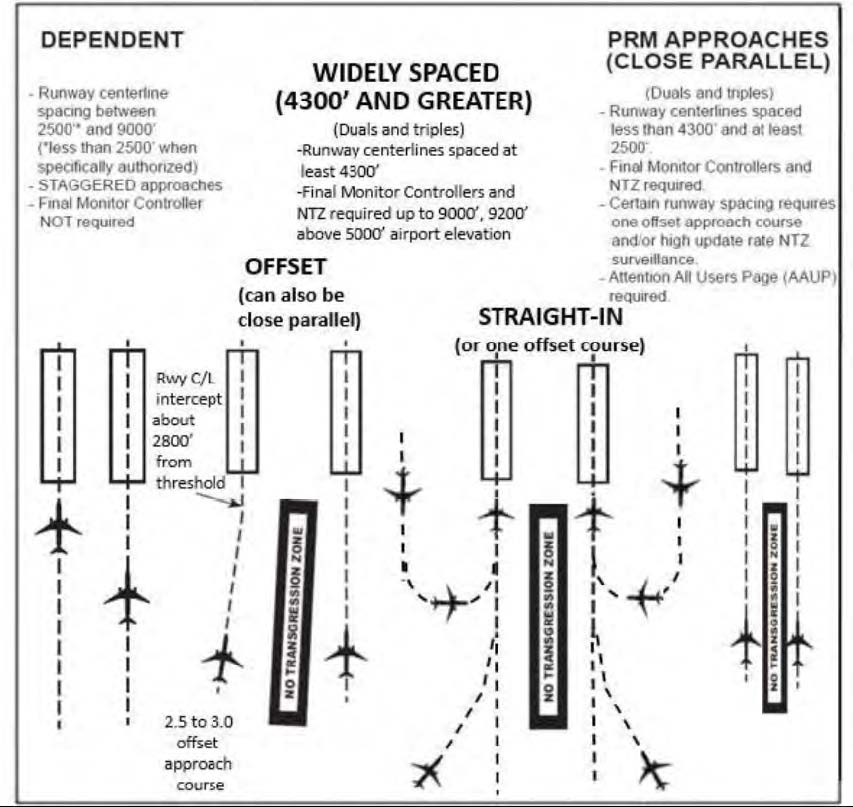
- ATC procedures permit ILS/RNAV/GLS instrument approach operations to dual or triple parallel runway configurations. ILS/RNAV/GLS approaches to parallel runways are grouped into three classes: Simultaneous Dependent Approaches; Simultaneous Independent Approaches; and Simultaneous Close Parallel PRM Approaches. RNAV approach procedures that are approved for simultaneous operations require GPS as the sensor for position updating. VOR/DME, DME/DME and IRU RNAV updating is not authorized. The classification of a parallel runway approach procedure is dependent on adjacent parallel runway centerline separation, ATC procedures, and airport ATC final approach radar monitoring and communications capabilities. At some airports, one or more approach courses may be offset up to 3 degrees. ILS approaches with offset localizer configurations result in loss of Category II/III capabilities and an increase in decision altitude/height (50').
- Depending on weather conditions, traffic volume, and the specific combination of runways being utilized for arrival operations, a runway may be used for different types of simultaneous operations, including closely spaced dependent or independent approaches. Pilots should ensure that they understand the type of operation that is being conducted, and ask ATC for clarification if necessary.
- Parallel approach operations demand heightened pilot situational awareness. Once cleared for an approach procedure, each pilot must maintain the lateral and vertical path of the procedure unless otherwise instructed by ATC. Instrument approach procedures using a curved or straight path to transition to the final segment may be used in conjunction with simultaneous operations. Pilots may notice nearby aircraft on adjacent approaches. As each aircraft nears the final approach fix, it may appear to the pilots involved that these aircraft are on converging or intercepting flight tracks. The procedures provide safe separation between aircraft. Each pilot should maintain close adherence to the approach procedure. Each pilot should be prepared to take appropriate action should adjacent aircraft deviate in a manner that creates a collision hazard to their aircraft and notify ATC. Pilots are informed by ATC or through the ATIS that simultaneous approaches are in use.
- The close proximity of adjacent aircraft conducting simultaneous independent approaches, especially simultaneous close parallel PRM approaches mandates strict pilot compliance with all ATC clearances. ATC assigned airspeeds, altitudes, and headings must be complied with in a timely manner. Autopilot coupled approaches require pilot knowledge of procedures necessary to comply with ATC instructions. Simultaneous independent approaches, particularly simultaneous close parallel PRM approaches necessitate precise approach course tracking to minimize final monitor controller intervention, and unwanted No Transgression Zone (NTZ) penetration. In the unlikely event of a breakout, ATC will not assign altitudes lower than the minimum vectoring altitude. Pilots should notify ATC immediately if there is a degradation of aircraft or navigation systems.
-
Strict radio discipline is mandatory during simultaneous independent and simultaneous close parallel PRM approach operations. This includes an alert listening watch and the avoidance of lengthy, unnecessary radio transmissions. Attention must be given to proper call sign usage to prevent the inadvertent execution of clearances intended for another aircraft. Use of abbreviated call signs must be avoided to preclude confusion of aircraft with similar sounding call signs. Pilots must be alert to unusually long periods of silence or any unusual background sounds in their radio receiver. A stuck microphone may block the issuance of ATC instructions on the tower frequency by the final monitor controller during simultaneous independent and simultaneous close parallel PRM approaches. In the case of PRM approaches, the use of a second frequency by the monitor controller mitigates the “stuck mike” or other blockage on the tower frequency.
REFERENCE-
AIM, Chapter 4, Section 2, Radio Communications Phraseology and Techniques, gives additional communications information.
- Use of Traffic Collision Avoidance Systems (TCAS) provides an additional element of safety to parallel approach operations. Pilots should follow recommended TCAS operating procedures presented in approved flight manuals, original equipment manufacturer recommendations, professional newsletters, and FAA publications.
-
Simultaneous Dependent Approaches
FIG 5-4-21
Simultaneous Approaches (Parallel Runways and Approach Courses)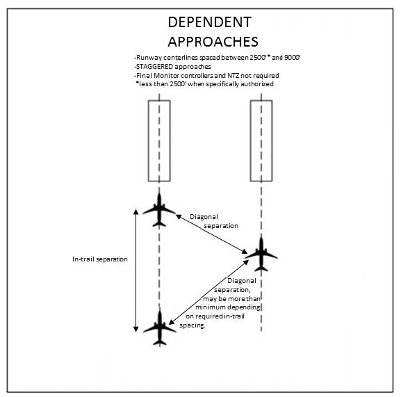
- Simultaneous dependent approaches are an ATC procedure permitting approaches to airports having parallel runway centerlines separated by at least 2,500 feet up to 9,000 feet. Integral parts of a total system are ILS or other system providing approach navigation, radar, communications, ATC procedures, and required airborne equipment. RNAV equipment in the aircraft or GLS equipment on the ground and in the aircraft may replace the required airborne and ground based ILS equipment. Although non-precision minimums may be published, pilots must only use those procedures specifically authorized by chart note. For example, the chart note “LNAV NA during simultaneous operations,” requires vertical guidance. When given a choice, pilots should always fly a precision approach whenever possible.
- A simultaneous dependent approach differs from a simultaneous independent approach in that, the minimum distance between parallel runway centerlines may be reduced; there is no requirement for radar monitoring or advisories; and a staggered separation of aircraft on the adjacent final course is required.
- A minimum of 1.0 NM radar separation (diagonal) is required between successive aircraft on the adjacent final approach course when runway centerlines are at least 2,500 feet but no more than 3,600 feet apart. A minimum of 1.5 NM radar separation (diagonal) is required between successive aircraft on the adjacent final approach course when runway centerlines are more than 3,600 feet but no more than 8,300 feet apart. When runway centerlines are more than 8,300 feet but no more than 9,000 feet apart a minimum of 2 NM diagonal radar separation is provided. Aircraft on the same final approach course within 10 NM of the runway end are provided a minimum of 3 NM radar separation, reduced to 2.5 NM in certain circumstances. In addition, a minimum of 1,000 feet vertical or a minimum of three miles radar separation is provided between aircraft during turn on to the parallel final approach course.
-
Whenever parallel approaches are in use, pilots are informed by ATC or via the ATIS that approaches to both runways are in use. The charted IAP also notes which runways may be used simultaneously. In addition, the radar controller will have the interphone capability of communicating with the tower controller where separation responsibility has not been delegated to the tower.
NOTE-
ATC will not specifically identify these operations as being dependent when advertised on the ATIS.
EXAMPLE-
Simultaneous ILS Runway 19 right and ILS Runway 19 left in use.
-
At certain airports, simultaneous dependent approaches are permitted to runways spaced less than 2,500 feet apart. In this case, ATC will provide no less than the minimum authorized diagonal separation with the leader always arriving on the same runway. The trailing aircraft is permitted reduced diagonal separation, instead of the single runway separation normally utilized for runways spaced less than 2,500 feet apart. For wake turbulence mitigation reasons:
- Reduced diagonal spacing is only permitted when certain aircraft wake category pairings exist; typically when the leader is either in the large or small wake turbulence category, and
-
All aircraft must descend on the glideslope from the altitude at which they were cleared for the approach during these operations.
When reduced separation is authorized, the IAP briefing strip indicates that simultaneous operations require the use of vertical guidance and that the pilot should maintain last assigned altitude until intercepting the glideslope. No special pilot training is required to participate in these operations.NOTE-
Either simultaneous dependent approaches with reduced separation or SOIA PRM approaches may be conducted to Runways 28R and 28L at KSFO spaced 750 feet apart, depending on weather conditions and traffic volume. Pilots should use caution so as not to confuse these operations. Plan for SOIA procedures only when ATC assigns a PRM approach or the ATIS advertises PRM approaches are in use. KSFO is the only airport where both procedures are presently conducted.
REFERENCE-
AIM, Para 5-4-16, Simultaneous Close Parallel PRM Approaches and Simultaneous Offset Instrument Approaches (SOIA).
-
Simultaneous Independent ILS/RNAV/GLS Approaches
FIG 5-4-22
Simultaneous Independent ILS/RNAV/GLS Approaches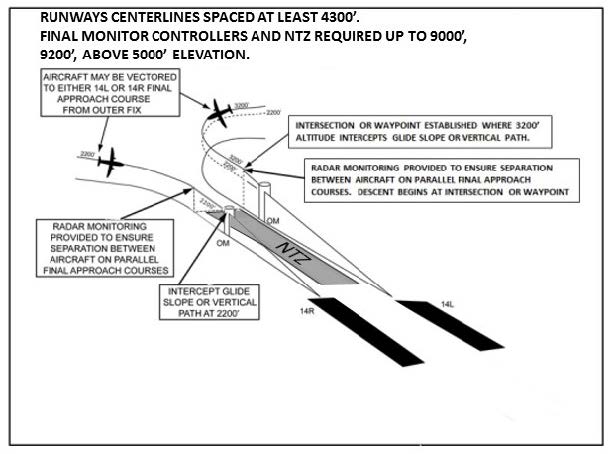
-
System. An approach system permitting simultaneous approaches to parallel runways with centerlines separated by at least 4,300 feet. Separation between 4,300 and 9,000 feet (9,200' for airports above 5,000') utilizing NTZ final monitor controllers. Simultaneous independent approaches require NTZ radar monitoring to ensure separation between aircraft on the adjacent parallel approach course. Aircraft position is tracked by final monitor controllers who will issue instructions to aircraft observed deviating from the assigned final approach course. Staggered radar separation procedures are not utilized. Integral parts of a total system are radar, communications, ATC procedures, and ILS or other required airborne equipment. A chart note identifies that the approach is authorized for simultaneous use.
When simultaneous operations are in use, it will be advertised on the ATIS. When advised that simultaneous approaches are in use, pilots must advise approach control immediately of malfunctioning or inoperative receivers, or if a simultaneous approach is not desired. Although non-precision minimums may be published, pilots must only use those procedures specifically authorized by chart note. For example, the chart note “LNAV NA during simultaneous operations,” requires vertical guidance. When given a choice, pilots should always fly a precision approach whenever possible.NOTE-
ATC does not use the word independent or parallel when advertising these operations on the ATIS.
EXAMPLE-
Simultaneous ILS Runway 24 left and ILS Runway 24 right approaches in use.
-
Radar Services. These services are provided for each simultaneous independent approach.
-
During turn on to parallel final approach, aircraft are normally provided 3 miles radar separation or a minimum of 1,000 feet vertical separation. The assigned altitude must be maintained until intercepting the glidepath, unless cleared otherwise by ATC. Aircraft will not be vectored to intercept the final approach course at an angle greater than thirty degrees.
NOTE-
Some simultaneous operations permit the aircraft to track an RNAV course beginning on downwind and continuing in a turn to intercept the final approach course. In this case, separation with the aircraft on the adjacent final approach course is provided by the monitor controller with reference to an NTZ.
- The final monitor controller will have the capability of overriding the tower controller on the tower frequency.
- Pilots will be instructed to contact the tower frequency prior to the point where NTZ monitoring begins.
-
Aircraft observed to overshoot the turn-on or to continue on a track which will penetrate the NTZ will be instructed to return to the correct final approach course immediately. The final monitor controller may cancel the approach clearance, and issue missed approach or other instructions to the deviating aircraft.
PHRASEOLOGY-
“(Aircraft call sign) YOU HAVE CROSSED THE FINAL APPROACH COURSE. TURN (left/right) IMMEDIATELY AND RETURN TO THE FINAL APPROACH COURSE,”
or
“(aircraft call sign) TURN (left/right) AND RETURN TO THE FINAL APPROACH COURSE.” -
If a deviating aircraft fails to respond to such instructions or is observed penetrating the NTZ, the aircraft on the adjacent final approach course (if threatened), will be issued a breakout instruction.
PHRASEOLOGY-
“TRAFFIC ALERT (aircraft call sign) TURN (left/right) IMMEDIATELY HEADING (degrees), (climb/descend) AND MAINTAIN (altitude).”
-
Radar monitoring will automatically be terminated when visual separation is applied, the aircraft reports the approach lights or runway in sight, or the aircraft is 1 NM or less from the runway threshold. Final monitor controllers will not advise pilots when radar monitoring is terminated.
NOTE-
Simultaneous independent approaches conducted to runways spaced greater than 9,000 feet (or 9,200' at airports above 5,000') do not require an NTZ. However, from a pilot's perspective, the same alerts relative to deviating aircraft will be provided by ATC as are provided when an NTZ is being monitored. Pilots may not be aware as to whether or not an NTZ is being monitored.
-
During turn on to parallel final approach, aircraft are normally provided 3 miles radar separation or a minimum of 1,000 feet vertical separation. The assigned altitude must be maintained until intercepting the glidepath, unless cleared otherwise by ATC. Aircraft will not be vectored to intercept the final approach course at an angle greater than thirty degrees.
-
System. An approach system permitting simultaneous approaches to parallel runways with centerlines separated by at least 4,300 feet. Separation between 4,300 and 9,000 feet (9,200' for airports above 5,000') utilizing NTZ final monitor controllers. Simultaneous independent approaches require NTZ radar monitoring to ensure separation between aircraft on the adjacent parallel approach course. Aircraft position is tracked by final monitor controllers who will issue instructions to aircraft observed deviating from the assigned final approach course. Staggered radar separation procedures are not utilized. Integral parts of a total system are radar, communications, ATC procedures, and ILS or other required airborne equipment. A chart note identifies that the approach is authorized for simultaneous use.
-
Simultaneous Close Parallel PRM Approaches and Simultaneous Offset Instrument Approaches (SOIA)
FIG 5-4-23
PRM Approaches Simultaneous Close Parallel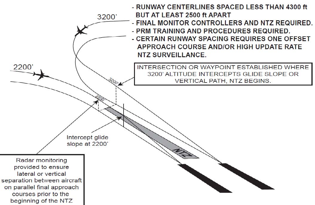
-
System.
-
PRM is an acronym for the high update rate Precision Runway Monitor surveillance system which is required to monitor the No Transgression Zone (NTZ) for specific parallel runway separations used to conduct simultaneous close parallel approaches. PRM is also published in the title as part of the approach name for IAPs used to conduct Simultaneous Close Parallel approaches. “PRM” alerts pilots that specific airborne equipment, training, and procedures are applicable.
Because Simultaneous Close Parallel PRM approaches are independent, the NTZ and normal operating zone (NOZ) airspace between the final approach courses is monitored by two monitor controllers, one for each approach course. The NTZ monitoring system (final monitor aid) consists of a high resolution ATC radar display with automated tracking software which provides monitor controllers with aircraft identification, position, speed, and a ten-second projected position, as well as visual and aural NTZ penetration alerts. A PRM high update rate surveillance sensor is a component of this system only for specific runway spacing. Additional procedures for simultaneous independent approaches are described in paragraph 5-4-15, Simultaneous Independent ILS/RNAV/GLS Approaches. -
Simultaneous Close Parallel PRM approaches, whether conducted utilizing a high update rate PRM surveillance sensor or not, must meet all of the following requirements: pilot training, PRM in the approach title, NTZ monitoring utilizing a final monitor aid, radar display, publication of an AAUP, and use of a secondary PRM communications frequency. PRM approaches are depicted on a separate IAP titled (Procedure type) PRM Rwy XXX (Simultaneous Close Parallel or Close Parallel).
NOTE-
ATC does not use the word “independent” when advertising these operations on the ATIS.
EXAMPLE-
Simultaneous ILS PRM Runway 33 left and ILS PRM Runway 33 right approaches in use.
- The pilot may request to conduct a different type of PRM approach to the same runway other than the one that is presently being used; for example, RNAV instead of ILS. However, pilots must always obtain ATC approval to conduct a different type of approach. Also, in the event of the loss of ground-based NAVAIDS, the ATIS may advertise other types of PRM approaches to the affected runway or runways.
- The Attention All Users Page (AAUP) will address procedures for conducting PRM approaches.
-
PRM is an acronym for the high update rate Precision Runway Monitor surveillance system which is required to monitor the No Transgression Zone (NTZ) for specific parallel runway separations used to conduct simultaneous close parallel approaches. PRM is also published in the title as part of the approach name for IAPs used to conduct Simultaneous Close Parallel approaches. “PRM” alerts pilots that specific airborne equipment, training, and procedures are applicable.
-
Requirements and Procedures. Besides system requirements and pilot procedures as identified in subparagraph a1 above, all pilots must have completed special training before accepting a clearance to conduct a PRM approach.
-
Pilot Training Requirement. Pilots must complete special pilot training, as outlined below, before accepting a clearance for a simultaneous close parallel PRM approach.
- For operations under 14 CFR parts 121, 129, and 135, pilots must comply with FAA-approved company training as identified in their Operations Specifications. Training includes the requirement for pilots to view the FAA training slide presentation, “Precision Runway Monitor (PRM) Pilot Procedures.” Refer to https://www.faa.gov/training_testing/training/prm/ or search key words “FAA PRM” for additional information and to view or download the slide presentation.
-
For operations under part 91:
- Pilots operating transport category aircraft must be familiar with PRM operations as contained in this section of the AIM. In addition, pilots operating transport category aircraft must view the slide presentation, “Precision Runway Monitor (PRM) Pilot Procedures.” Refer to https://www.faa.gov/training_testing/training/prm/ or search key words “FAA PRM” for additional information and to view or download the slide presentation.
-
Pilots not operating transport category aircraft must be familiar with PRM and SOIA operations as contained in this section of the AIM. The FAA strongly recommends that pilots not involved in transport category aircraft operations view the FAA training slide presentation, “Precision Runway Monitor (PRM) Pilot Procedures.” Refer to https://www.faa.gov/training_testing/training/prm/ or search key words “FAA PRM” for additional information and to view or download the slide presentation.
NOTE-
Depending on weather conditions, traffic volume, and the specific combination of runways being utilized for arrival operations, a runway may be used for different types of simultaneous operations, including closely spaced dependent or independent approaches. Use PRM procedures only when the ATIS advertises their use. For other types of simultaneous approaches, see paragraphs 5-4-14 and 5-4-15.
-
Pilot Training Requirement. Pilots must complete special pilot training, as outlined below, before accepting a clearance for a simultaneous close parallel PRM approach.
- ATC Directed Breakout. An ATC directed “breakout” is defined as a vector off the final approach course of a threatened aircraft in response to another aircraft penetrating the NTZ.
- Dual Communications. The aircraft flying the PRM approach must have the capability of enabling the pilot/s to listen to two communications frequencies simultaneously. To avoid blocked transmissions, each runway will have two frequencies, a primary and a PRM monitor frequency. The tower controller will transmit on both frequencies. The monitor controller's transmissions, if needed, will override both frequencies. Pilots will ONLY transmit on the tower controller's frequency, but will listen to both frequencies. Select the PRM monitor frequency audio only when instructed by ATC to contact the tower. The volume levels should be set about the same on both radios so that the pilots will be able to hear transmissions on the PRM frequency if the tower is blocked. Site-specific procedures take precedence over the general information presented in this paragraph. Refer to the AAUP for applicable procedures at specific airports.
-
Radar Services.
- During turn on to parallel final approach, aircraft will be provided 3 miles radar separation or a minimum of 1,000 feet vertical separation. The assigned altitude must be maintained until intercepting the glideslope/glidepath, unless cleared otherwise by ATC. Aircraft will not be vectored to intercept the final approach course at an angle greater than thirty degrees.
- The final monitor controller will have the capability of overriding the tower controller on the tower frequency as well as transmitting on the PRM frequency.
- Pilots will be instructed to contact the tower frequency prior to the point where NTZ monitoring begins. Pilots will begin monitoring the secondary PRM frequency at that time (see Dual VHF Communications Required below).
- To ensure separation is maintained, and in order to avoid an imminent situation during PRM approaches, pilots must immediately comply with monitor controller instructions.
-
Aircraft observed to overshoot the turn or to continue on a track which will penetrate the NTZ will be instructed to return to the correct final approach course immediately. The final monitor controller may cancel the approach clearance, and issue missed approach or other instructions to the deviating aircraft.
PHRASEOLOGY-
“(Aircraft call sign) YOU HAVE CROSSED THE FINAL APPROACH COURSE. TURN (left/right) IMMEDIATELY AND RETURN TO THE FINAL APPROACH COURSE,”
or
“(Aircraft call sign) TURN (left/right) AND RETURN TO THE FINAL APPROACH COURSE.” -
If a deviating aircraft fails to respond to such instructions or is observed penetrating the NTZ, the aircraft on the adjacent final approach course (if threatened) will be issued a breakout instruction.
PHRASEOLOGY-
“TRAFFIC ALERT (aircraft call sign) TURN (left/right) IMMEDIATELY HEADING (degrees), (climb/descend) AND MAINTAIN (altitude).”
- Radar monitoring will automatically be terminated when visual separation is applied, or the aircraft reports the approach lights or runway in sight or within 1 NM of the runway threshold. Final monitor controllers will not advise pilots when radar monitoring is terminated.
-
Attention All Users Page (AAUP). At airports that conduct PRM operations, the AAUP informs pilots under the “General” section of information relative to all the PRM approaches published at a specific airport, and this section must be briefed in its entirety. Under the “Runway Specific” section, only items relative to the runway to be used for landing need be briefed. (See FIG 5-4-24.) A single AAUP is utilized for multiple PRM approach charts at the same airport, which are listed on the AAUP. The requirement for informing ATC if the pilot is unable to accept a PRM clearance is also presented. The “General” section of AAUP addresses the following:
- Review of the procedure for executing a climbing or descending breakout;
- Breakout phraseology beginning with the words, “Traffic Alert;”
- Descending on the glideslope/glidepath meets all crossing restrictions;
- Briefing the PRM approach also satisfies the non-PRM approach briefing of the same type of approach to the same runway; and
-
Description of the dual communications procedure.
The “Runway Specific” section of the AAUP addresses those issues which only apply to certain runway ends that utilize PRM approaches. There may be no Runway Specific procedures, a single item applicable to only one runway end, or multiple items for a single or multiple runway end/s. Examples of SOIA runway specific procedures are as follows:FIG 5-4-24
PRM Attention All Users Page (AAUP)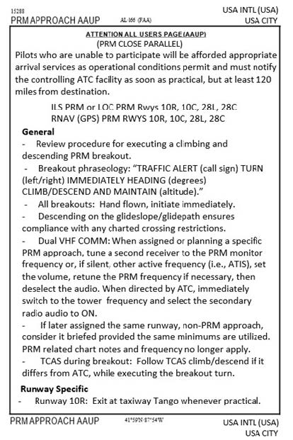
-
Simultaneous Offset Instrument Approach (SOIA).
- SOIA is a procedure used to conduct simultaneous approaches to runways spaced less than 3,000 feet, but at least 750 feet apart. The SOIA procedure utilizes a straight-in PRM approach to one runway, and a PRM offset approach with glideslope/glidepath to the adjacent runway. In SOIA operations, aircraft are paired, with the aircraft conducting the straight-in PRM approach always positioned slightly ahead of the aircraft conducting the offset PRM approach.
- The straight-in PRM approach plates used in SOIA operations are identical to other straight-in PRM approach plates, with an additional note, which provides the separation between the two runways used for simultaneous SOIA approaches. The offset PRM approach plate displays the required notations for closely spaced approaches as well as depicts the visual segment of the approach.
- Controllers monitor the SOIA PRM approaches in exactly the same manner as is done for other PRM approaches. The procedures and system requirements for SOIA PRM approaches are identical with those used for simultaneous close parallel PRM approaches until near the offset PRM approach missed approach point (MAP), where visual acquisition of the straight-in aircraft by the aircraft conducting the offset PRM approach occurs. Since SOIA PRM approaches are identical to other PRM approaches (except for the visual segment in the offset approach), an understanding of the procedures for conducting PRM approaches is essential before conducting a SOIA PRM operation.
- In SOIA, the approach course separation (instead of the runway separation) meets established close parallel approach criteria. (See FIG 5-4-25 for the generic SOIA approach geometry.) A visual segment of the offset PRM approach is established between the offset MAP and the runway threshold. Aircraft transition in visual conditions from the offset course, beginning at the offset MAP, to align with the runway and can be stabilized by 500 feet above ground level (AGL) on the extended runway centerline. A cloud ceiling for the approach is established so that the aircraft conducting the offset approach has nominally at least 30 seconds or more to acquire the leading straight-in aircraft prior to reaching the offset MAP. If visual acquisition is not accomplished prior to crossing the offset MAP, a missed approach must be executed.
-
Flight Management System (FMS) coding of the offset RNAV PRM and GLS PRM approaches in a SOIA operation is different than other RNAV and GLS approach coding in that it does not match the initial missed approach procedure published on the charted IAP. In the SOIA design of the offset approach, lateral course guidance terminates at the fictitious threshold point (FTP), which is an extension of the final approach course beyond the offset MAP to a point near the runway threshold. The FTP is designated in the approach coding as the MAP so that vertical guidance is available to the pilot to the runway threshold, just as vertical guidance is provided by the offset LDA glideslope. No matter what type of offset approach is being conducted, reliance on lateral guidance is discontinued at the charted MAP and replaced by visual maneuvering to accomplish runway alignment.
- As a result of this approach coding, when executing a missed approach at and after passing the charted offset MAP, a heading must initially be flown (either hand-flown or using autopilot “heading mode”) before engaging LNAV. If the pilot engages LNAV immediately, the aircraft may continue to track toward the FTP instead of commencing a turn toward the missed approach holding fix. Notes on the charted IAP and in the AAUP make specific reference to this procedure.
- Some FMSs do not code waypoints inside of the FAF as part of the approach. Therefore, the depicted MAP on the charted IAP may not be included in the offset approach coding. Pilots utilizing those FMSs may identify the location of the waypoint by noting its distance from the FTP as published on the charted IAP. In those same FMSs, the straight-in SOIA approach will not display a waypoint inside the PFAF. The same procedures may be utilized to identify an uncoded waypoint. In this case, the location is determined by noting its distance from the runway waypoint or using an authorized distance as published on the charted IAP.
-
Because the FTP is coded as the MAP, the FMS map display will depict the initial missed approach course as beginning at the FTP. This depiction does not match the charted initial missed approach procedure on the IAP. Pilots are reminded that charted IAP guidance is to be followed, not the map display. Once the aircraft completes the initial turn when commencing a missed approach, the remainder of the procedure coding is standard and can be utilized as with any other IAP.
FIG 5-4-25
SOIA Approach Geometry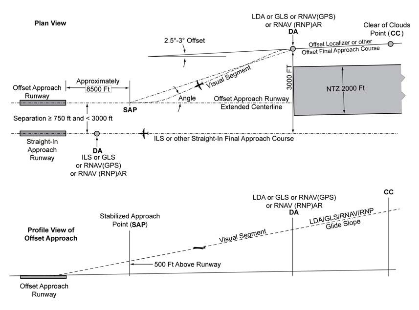
NOTE-
SAP
The stabilized approach point is a design point along the extended centerline of the intended landing runway on the glide slope/glide path at 500 feet above the runway threshold elevation. It is used to verify a sufficient distance is provided for the visual maneuver after the offset course approach DA to permit the pilots to conform to approved, stabilized approach criteria. The SAP is not published on the IAP.
Offset Course DA
The point along the LDA, or other offset course, where the course separation with the adjacent ILS, or other straight-in course, reaches the minimum distance permitted to conduct closely spaced approaches. Typically that minimum distance will be 3,000 feet without the use of high update radar; with high update radar, course separation of less than 3,000 ft may be used when validated by a safety study. The altitude of the glide slope/glide path at that point determines the offset course approach decision altitude and is where the NTZ terminates. Maneuvering inside the DA is done in visual conditions.
Visual Segment Angle
Angle, as determined by the SOIA design tool, formed by the extension of the straight segment of the calculated flight track (between the offset course MAP/DA and the SAP) and the extended runway centerline. The size of the angle is dependent on the aircraft approach categories (Category D or only selected categories/speeds) that are authorized to use the offset course approach and the spacing between the runways.
Visibility
Distance from the offset course approach DA to runway threshold in statute mile.
Procedure
The aircraft on the offset course approach must see the runway-landing environment and, if ATC has advised that traffic on the straight-in approach is a factor, the offset course approach aircraft must visually acquire the straight-in approach aircraft and report it in sight to ATC prior to reaching the DA for the offset course approach.
CC
The Clear of Clouds point is the position on the offset final approach course where aircraft first operate in visual meteorological conditions below the ceiling, when the actual weather conditions are at, or near, the minimum ceiling for SOIA operations. Ceiling is defined by the Aeronautical Information Manual.
-
SOIA PRM approaches utilize the same dual communications procedures as do other PRM approaches.
NOTE-
At KSFO, pilots conducting SOIA operations select the monitor frequency audio when communicating with the final radar controller, not the tower controller as is customary. In this special case, the monitor controller's transmissions, if required, override the final controller's frequency. This procedure is addressed on the AAUP.
- SOIA utilizes the same AAUP format as do other PRM approaches. The minimum weather conditions that are required are listed. Because of the more complex nature of instructions for conducting SOIA approaches, the “Runway Specific” items are more numerous and lengthy.
-
Examples of SOIA offset runway specific notes:
- Aircraft must remain on the offset course until passing the offset MAP prior to maneuvering to align with the centerline of the offset approach runway.
-
Pilots are authorized to continue past the offset MAP to align with runway centerline when:
- the straight-in approach traffic is in sight and is expected to remain in sight,
- ATC has been advised that “traffic is in sight.” (ATC is not required to acknowledge this transmission),
- the runway environment is in sight. Otherwise, a missed approach must be executed. Between the offset MAP and the runway threshold, pilots conducting the offset PRM approach must not pass the straight-in aircraft and are responsible for separating themselves visually from traffic conducting the straight-in PRM approach to the adjacent runway, which means maneuvering the aircraft as necessary to avoid that traffic until landing, and providing wake turbulence avoidance, if applicable. Pilots maintaining visual separation should advise ATC, as soon as practical, if visual contact with the aircraft conducting the straight-in PRM approach is lost and execute a missed approach unless otherwise instructed by ATC.
-
Examples of SOIA straight-in runway specific notes:
- To facilitate the offset aircraft in providing wake mitigation, pilots should descend on, not above, the glideslope/glidepath.
- Conducting the straight-in approach, pilots should be aware that the aircraft conducting the offset approach will be approaching from the right/left rear and will be operating in close proximity to the straight-in aircraft.
-
Recap.
The following are differences between widely spaced simultaneous approaches (at least 4,300 feet between the runway centerlines) and Simultaneous PRM close parallel approaches which are of importance to the pilot:- Runway Spacing. Prior to PRM simultaneous close parallel approaches, most ATC-directed breakouts were the result of two aircraft in-trail on the same final approach course getting too close together. Two aircraft going in the same direction did not mandate quick reaction times. With PRM closely spaced approaches, two aircraft could be alongside each other, navigating on courses that are separated by less than 4,300 feet and as close as 3,000 feet. In the unlikely event that an aircraft “blunders” off its course and makes a worst case turn of 30 degrees toward the adjacent final approach course, closing speeds of 135 feet per second could occur that constitute the need for quick reaction. A blunder has to be recognized by the monitor controller, and breakout instructions issued to the endangered aircraft. The pilot will not have any warning that a breakout is imminent because the blundering aircraft will be on another frequency. It is important that, when a pilot receives breakout instructions, the assumption is made that a blundering aircraft is about to (or has penetrated the NTZ) and is heading toward his/her approach course. The pilot must initiate a breakout as soon as safety allows. While conducting PRM approaches, pilots must maintain an increased sense of awareness in order to immediately react to an ATC (breakout) instruction and maneuver (as instructed by ATC) away from a blundering aircraft.
- Communications. Dual VHF communications procedures should be carefully followed. One of the assumptions made that permits the safe conduct of PRM approaches is that there will be no blocked communications.
- Hand-flown Breakouts. The use of the autopilot is encouraged while flying a PRM approach, but the autopilot must be disengaged in the rare event that a breakout is issued. Simulation studies of breakouts have shown that a hand-flown breakout can be initiated consistently faster than a breakout performed using the autopilot.
-
TCAS. The ATC breakout instruction is the primary means of conflict resolution. TCAS, if installed, provides another form of conflict resolution in the unlikely event other separation standards would fail. TCAS is not required to conduct a closely spaced approach.
The TCAS provides only vertical resolution of aircraft conflicts, while the ATC breakout instruction provides both vertical and horizontal guidance for conflict resolutions. Pilots should always immediately follow the TCAS Resolution Advisory (RA), whenever it is received. Should a TCAS RA be received before, during, or after an ATC breakout instruction is issued, the pilot should follow the RA, even if it conflicts with the climb/descent portion of the breakout maneuver. If following an RA requires deviating from an ATC clearance, the pilot must advise ATC as soon as practical. While following an RA, it is extremely important that the pilot also comply with the turn portion of the ATC breakout instruction unless the pilot determines safety to be factor. Adhering to these procedures assures the pilot that acceptable “breakout” separation margins will always be provided, even in the face of a normal procedural or system failure.
-
System.
-
Simultaneous Converging Instrument Approaches
- ATC may conduct instrument approaches simultaneously to converging runways; i.e., runways having an included angle from 15 to 100 degrees, at airports where a program has been specifically approved to do so.
- The basic concept requires that dedicated, separate standard instrument approach procedures be developed for each converging runway included. These approaches can be identified by the letter “V” in the title; for example, “ILS V Rwy 17 (CONVERGING)”. Missed Approach Points must be at least 3 miles apart and missed approach procedures ensure that missed approach protected airspace does not overlap.
- Other requirements are: radar availability, nonintersecting final approach courses, precision approach capability for each runway and, if runways intersect, controllers must be able to apply visual separation as well as intersecting runway separation criteria. Intersecting runways also require minimums of at least 700 foot ceilings and 2 miles visibility. Straight in approaches and landings must be made.
- Whenever simultaneous converging approaches are in use, aircraft will be informed by the controller as soon as feasible after initial contact or via ATIS. Additionally, the radar controller will have direct communications capability with the tower controller where separation responsibility has not been delegated to the tower.
-
RNP AR (Authorization Required) Instrument Procedures
- RNP AR procedures require authorization analogous to the special authorization required for Category II or III ILS procedures. All operators require specific authorization from the FAA to fly any RNP AR approach or departure procedure. The FAA issues RNP AR authorization via operations specification (OpSpec), management specification (MSpec), or letter of authorization (LOA). There are no exceptions. Operators can find comprehensive information on RNP AR aircraft eligibility, operating procedures, and training requirements in AC 90-101, Approval Guidance for RNP Procedures with AR.
- Unique characteristics of RNP AR Operations Approach title. The FAA titles all RNP AR instrument approach procedures (IAP) as “RNAV (RNP) RWY XX.” Internationally, operators may find RNP AR IAPs titled “RNP RWY XX (AR).” All RNP AR procedures will clearly state “Authorization Required” on the procedure chart.
- RNP value. RNP AR procedures are characterized by use of a lateral Obstacle Evaluation Area (OEA) equal to two times the RNP value (2 x RNP) in nautical miles. No secondary lateral OEA or additional buffers are used. RNP AR procedures require a minimum lateral accuracy value of RNP 0.30. Each published line of minima in an RNP AR procedure has an associated RNP value that defines the procedure's lateral performance requirement in the Final Approach Segment. Each approved RNP AR operator's FAA-issued authorization will identify a minimum authorized RNP approach value. This value may vary depending on aircraft configuration or operational procedures (e.g., use of flight director or autopilot).
- Radius-to-fix (RF) legs. Many RNP AR IFPs contain RF legs. Aircraft eligibility for RF legs is required in any authorization for RNP AR operations.
- Missed Approach RNP value less than 1.00 NM. Some RNP AR IFPs require an RNP lateral accuracy value of less than 1.00 NM in the missed approach segment. The operator's FAA-issued RNP AR authorization will specify whether the operator may fly a missed approach procedure requiring a lateral accuracy value less than 1.00 NM. AC 90-101 identifies specific operating procedures and training requirements applicable to this aspect of RNP AR procedures.
- Non-standard speeds or climb gradients. RNP AR approaches may require non-standard approach speeds and/or missed approach climb gradients. RNP AR approach charts will reflect any non-standard requirements and pilots must confirm they can meet those requirements before commencing the approach.
-
RNP AR Departure Procedures (RNP AR DP). RNP AR approach authorization is a mandatory prerequisite for an operator to be eligible to perform RNP AR DPs. RNP AR DPs can utilize a minimum RNP value of RNP 0.30, may include higher than standard climb gradients, and may include RF turns. Close in RF turns associated with RNP AR DPs may begin as soon as the departure end of the runway (DER). For specific eligibility guidance, operators should refer to AC 90-101.
FIG 5-4-26
Example of an RNP AR DP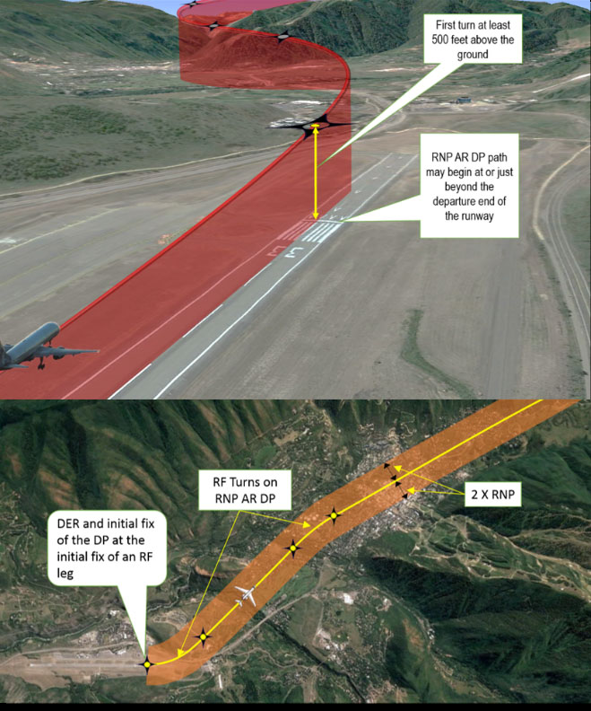
-
Side-step Maneuver
- ATC may authorize a standard instrument approach procedure which serves either one of parallel runways that are separated by 1,200 feet or less followed by a straight-in landing on the adjacent runway.
-
Aircraft that will execute a side-step maneuver will be cleared for a specified approach procedure and landing on the adjacent parallel runway. Example, “cleared ILS runway 7 left approach, side-step to runway 7 right.” Pilots are expected to commence the side-step maneuver as soon as possible after the runway or runway environment is in sight. Compliance with minimum altitudes associated with stepdown fixes is expected even after the side-step maneuver is initiated.
NOTE-
Side-step minima are flown to a Minimum Descent Altitude (MDA) regardless of the approach authorized.
- Landing minimums to the adjacent runway will be based on nonprecision criteria and therefore higher than the precision minimums to the primary runway, but will normally be lower than the published circling minimums.
-
Approach and Landing Minimums
- Landing Minimums. The rules applicable to landing minimums are contained in 14 CFR section 91.175. TBL 5-4-1 may be used to convert RVR to ground or flight visibility. For converting RVR values that fall between listed values, use the next higher RVR value; do not interpolate. For example, when converting 1800 RVR, use 2400 RVR with the resultant visibility of 1/2 mile.
-
Obstacle Clearance. Final approach obstacle clearance is provided from the start of the final segment to the runway or missed approach point, whichever occurs last. Side-step obstacle protection is provided by increasing the width of the final approach obstacle clearance area.
TBL 5-4-1
RVR Value ConversionsRVR
Visibility
(statute miles)1600
1/4
2400
1/2
3200
5/8
4000
3/4
4500
7/8
5000
1
6000
1 1/4
-
Circling approach protected areas are defined by the tangential connection of arcs drawn from each runway end (see FIG 5-4-27). Circling approach protected areas developed prior to late 2012 used fixed radius distances, dependent on aircraft approach category, as shown in the table on page B2 of the U.S. TPP. The approaches using standard circling approach areas can be identified by the absence of the “negative C" symbol on the circling line of minima. Circling approach protected areas developed after late 2012 use the radius distance shown in the table on page B2 of the U.S. TPP, dependent on aircraft approach category, and the altitude of the circling MDA, which accounts for true airspeed increase with altitude. The approaches using expanded circling approach areas can be identified by the presence of the “negative C" symbol on the circling line of minima (see FIG 5-4-28). Because of obstacles near the airport, a portion of the circling area may be restricted by a procedural note; for example, “Circling NA E of RWY 17-35.” Obstacle clearance is provided at the published minimums (MDA) for the pilot who makes a straight-in approach, side-steps, or circles. Once below the MDA the pilot must see and avoid obstacles. Executing the missed approach after starting to maneuver usually places the aircraft beyond the MAP. The aircraft is clear of obstacles when at or above the MDA while inside the circling area, but simply joining the missed approach ground track from the circling maneuver may not provide vertical obstacle clearance once the aircraft exits the circling area. Additional climb inside the circling area may be required before joining the missed approach track. See paragraph 5-4-21, Missed Approach, for additional considerations when starting a missed approach at other than the MAP.
FIG 5-4-27
Final Approach Obstacle Clearance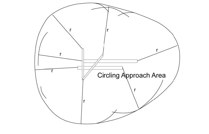
NOTE-
Circling approach area radii vary according to approach category and MSL circling altitude due to TAS changes—see FIG 5-4-28.
FIG 5-4-28
Standard and Expanded Circling Approach Radii in the U.S. TPP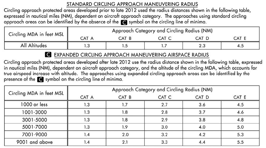
-
Precision Obstacle Free Zone (POFZ). A volume of airspace above an area beginning at the runway threshold, at the threshold elevation, and centered on the extended runway centerline. The POFZ is 200 feet (60m) long and 800 feet (240m) wide. The POFZ must be clear when an aircraft on a vertically guided final approach is within 2 nautical miles of the runway threshold and the official weather observation is a ceiling below 250 feet or visibility less than 3/4 statute mile (SM) (or runway visual range below 4,000 feet). If the POFZ is not clear, the MINIMUM authorized height above touchdown (HAT) and visibility is 250 feet and 3/4 SM. The POFZ is considered clear even if the wing of the aircraft holding on a taxiway waiting for runway clearance penetrates the POFZ; however, neither the fuselage nor the tail may infringe on the POFZ. The POFZ is applicable at all runway ends including displaced thresholds.
FIG 5-4-29
Precision Obstacle Free Zone (POFZ)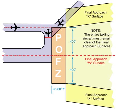
-
Circling approach protected areas are defined by the tangential connection of arcs drawn from each runway end (see FIG 5-4-27). Circling approach protected areas developed prior to late 2012 used fixed radius distances, dependent on aircraft approach category, as shown in the table on page B2 of the U.S. TPP. The approaches using standard circling approach areas can be identified by the absence of the “negative C" symbol on the circling line of minima. Circling approach protected areas developed after late 2012 use the radius distance shown in the table on page B2 of the U.S. TPP, dependent on aircraft approach category, and the altitude of the circling MDA, which accounts for true airspeed increase with altitude. The approaches using expanded circling approach areas can be identified by the presence of the “negative C" symbol on the circling line of minima (see FIG 5-4-28). Because of obstacles near the airport, a portion of the circling area may be restricted by a procedural note; for example, “Circling NA E of RWY 17-35.” Obstacle clearance is provided at the published minimums (MDA) for the pilot who makes a straight-in approach, side-steps, or circles. Once below the MDA the pilot must see and avoid obstacles. Executing the missed approach after starting to maneuver usually places the aircraft beyond the MAP. The aircraft is clear of obstacles when at or above the MDA while inside the circling area, but simply joining the missed approach ground track from the circling maneuver may not provide vertical obstacle clearance once the aircraft exits the circling area. Additional climb inside the circling area may be required before joining the missed approach track. See paragraph 5-4-21, Missed Approach, for additional considerations when starting a missed approach at other than the MAP.
- Straight-in Minimums are shown on the IAP when the final approach course is within 30 degrees of the runway alignment and a normal descent can be made from the IFR altitude shown on the IAP to the runway surface. When either the normal rate of descent or the runway alignment factor of 30 degrees is exceeded, a straight-in minimum is not published and a circling minimum applies. The fact that a straight-in minimum is not published does not preclude pilots from landing straight-in if they have the active runway in sight and have sufficient time to make a normal approach for landing. Under such conditions and when ATC has cleared them for landing on that runway, pilots are not expected to circle even though only circling minimums are published. If they desire to circle, they should advise ATC.
- Side-Step Maneuver Minimums. Landing minimums for a side-step maneuver to the adjacent runway will normally be higher than the minimums to the primary runway.
- Published Approach Minimums. Approach minimums are published for different aircraft categories and consist of a minimum altitude (DA, DH, MDA) and required visibility. These minimums are determined by applying the appropriate TERPS criteria. When a fix is incorporated in a nonprecision final segment, two sets of minimums may be published: one for the pilot that is able to identify the fix, and a second for the pilot that cannot. Two sets of minimums may also be published when a second altimeter source is used in the procedure. When a nonprecision procedure incorporates both a stepdown fix in the final segment and a second altimeter source, two sets of minimums are published to account for the stepdown fix and a note addresses minimums for the second altimeter source.
-
Circling Minimums. In some busy terminal areas, ATC may not allow circling and circling minimums will not be published. Published circling minimums provide obstacle clearance when pilots remain within the appropriate area of protection. Pilots should remain at or above the circling altitude until the aircraft is continuously in a position from which a descent to a landing on the intended runway can be made at a normal rate of descent using normal maneuvers. Circling may require maneuvers at low altitude, at low airspeed, and in marginal weather conditions. Pilots must use sound judgment, have an indepth knowledge of their capabilities, and fully understand the aircraft performance to determine the exact circling maneuver since weather, unique airport design, and the aircraft position, altitude, and airspeed must all be considered. The following basic rules apply:
- Maneuver the shortest path to the base or downwind leg, as appropriate, considering existing weather conditions. There is no restriction from passing over the airport or other runways.
- It should be recognized that circling maneuvers may be made while VFR or other flying is in progress at the airport. Standard left turns or specific instruction from the controller for maneuvering must be considered when circling to land.
-
At airports without a control tower, it may be desirable to fly over the airport to observe wind and turn indicators and other traffic which may be on the runway or flying in the vicinity of the airport.
REFERENCE-
AC 90-66A, Recommended Standards Traffic patterns for Aeronautical Operations at Airports without Operating Control Towers.
- The missed approach point (MAP) varies depending upon the approach flown. For vertically guided approaches, the MAP is at the decision altitude/decision height. Non-vertically guided and circling procedures share the same MAP and the pilot determines this MAP by timing from the final approach fix, by a fix, a NAVAID, or a waypoint. Circling from a GLS, an ILS without a localizer line of minima or an RNAV (GPS) approach without an LNAV line of minima is prohibited.
- Instrument Approach at a Military Field. When instrument approaches are conducted by civil aircraft at military airports, they must be conducted in accordance with the procedures and minimums approved by the military agency having jurisdiction over the airport.
-
Missed Approach
- When a landing cannot be accomplished, advise ATC and, upon reaching the missed approach point defined on the approach procedure chart, the pilot must comply with the missed approach instructions for the procedure being used or with an alternate missed approach procedure specified by ATC.
- Obstacle protection for missed approach is predicated on the missed approach being initiated at the decision altitude/decision height (DA/DH) or at the missed approach point and not lower than minimum descent altitude (MDA). A climb gradient of at least 200 feet per nautical mile is required, (except for Copter approaches, where a climb of at least 400 feet per nautical mile is required), unless a higher climb gradient is published in the notes section of the approach procedure chart. When higher than standard climb gradients are specified, the end point of the non-standard climb will be specified at either an altitude or a fix. Pilots must preplan to ensure that the aircraft can meet the climb gradient (expressed in feet per nautical mile) required by the procedure in the event of a missed approach, and be aware that flying at a higher than anticipated ground speed increases the climb rate requirement (feet per minute). Tables for the conversion of climb gradients (feet per nautical mile) to climb rate (feet per minute), based on ground speed, are included on page D1 of the U.S. Terminal Procedures booklets. Reasonable buffers are provided for normal maneuvers. However, no consideration is given to an abnormally early turn. Therefore, when an early missed approach is executed, pilots should, unless otherwise cleared by ATC, fly the IAP as specified on the approach plate to the missed approach point at or above the MDA or DH before executing a turning maneuver.
- If visual reference is lost while circling-to-land from an instrument approach, the missed approach specified for that particular procedure must be followed (unless an alternate missed approach procedure is specified by ATC). To become established on the prescribed missed approach course, the pilot should make an initial climbing turn toward the landing runway and continue the turn until established on the missed approach course. Inasmuch as the circling maneuver may be accomplished in more than one direction, different patterns will be required to become established on the prescribed missed approach course, depending on the aircraft position at the time visual reference is lost. Adherence to the procedure will help assure that an aircraft will remain laterally within the circling and missed approach obstruction clearance areas. Refer to paragraph h concerning vertical obstruction clearance when starting a missed approach at other than the MAP. (See FIG 5-4-30.)
- At locations where ATC radar service is provided, the pilot should conform to radar vectors when provided by ATC in lieu of the published missed approach procedure. (See FIG 5-4-31.)
- Some locations may have a preplanned alternate missed approach procedure for use in the event the primary NAVAID used for the missed approach procedure is unavailable. To avoid confusion, the alternate missed approach instructions are not published on the chart. However, the alternate missed approach holding pattern will be depicted on the instrument approach chart for pilot situational awareness and to assist ATC by not having to issue detailed holding instructions. The alternate missed approach may be based on NAVAIDs not used in the approach procedure or the primary missed approach. When the alternate missed approach procedure is implemented by NOTAM, it becomes a mandatory part of the procedure. The NOTAM will specify both the textual instructions and any additional equipment requirements necessary to complete the procedure. Air traffic may also issue instructions for the alternate missed approach when necessary, such as when the primary missed approach NAVAID fails during the approach. Pilots may reject an ATC clearance for an alternate missed approach that requires equipment not necessary for the published approach procedure when the alternate missed approach is issued after beginning the approach. However, when the alternate missed approach is issued prior to beginning the approach the pilot must either accept the entire procedure (including the alternate missed approach), request a different approach procedure, or coordinate with ATC for alternative action to be taken, i.e., proceed to an alternate airport, etc.
- When approach has been missed, request clearance for specific action; i.e., to alternative airport, another approach, etc.
- Pilots must ensure that they have climbed to a safe altitude prior to proceeding off the published missed approach, especially in nonradar environments. Abandoning the missed approach prior to reaching the published altitude may not provide adequate terrain clearance. Additional climb may be required after reaching the holding pattern before proceeding back to the IAF or to an alternate.
-
A clearance for an instrument approach procedure includes a clearance to fly the published missed approach procedure, unless otherwise instructed by ATC. The published missed approach procedure provides obstacle clearance only when the missed approach is conducted on the missed approach segment from or above the missed approach point, and assumes a climb rate of 200 feet/NM or higher, as published. If the aircraft initiates a missed approach at a point other than the missed approach point (see paragraph 5-4-5b), from below MDA or DA (H), or on a circling approach, obstacle clearance is not necessarily provided by following the published missed approach procedure, nor is separation assured from other air traffic in the vicinity.
FIG 5-4-30
Circling and Missed Approach Obstruction Clearance Areas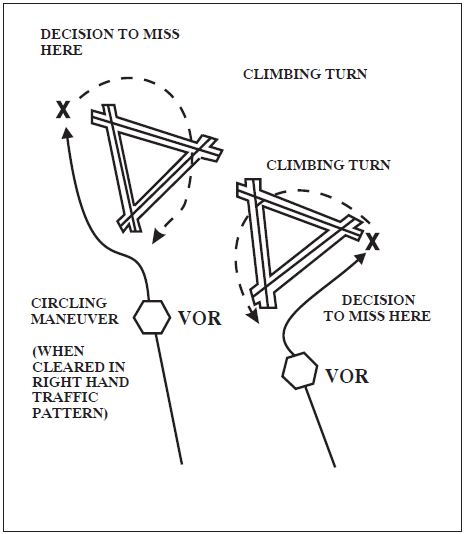
FIG 5-4-31
Missed Approach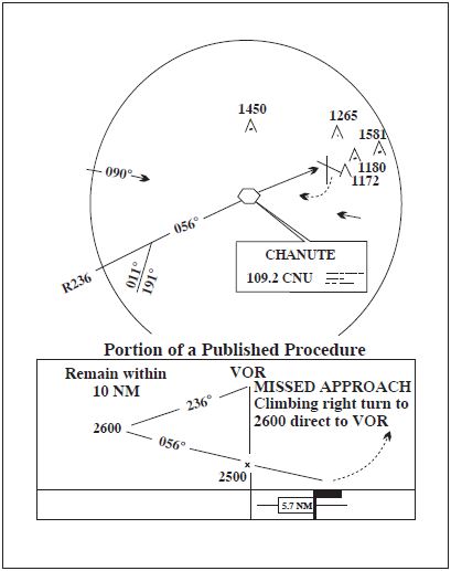 In the event a balked (rejected) landing occurs at a position other than the published missed approach point, the pilot should contact ATC as soon as possible to obtain an amended clearance. If unable to contact ATC for any reason, the pilot should attempt to re-intercept a published segment of the missed approach and comply with route and altitude instructions. If unable to contact ATC, and in the pilot's judgment it is no longer appropriate to fly the published missed approach procedure, then consider either maintaining visual conditions if practicable and reattempt a landing, or a circle-climb over the airport. Should a missed approach become necessary when operating to an airport that is not served by an operating control tower, continuous contact with an air traffic facility may not be possible. In this case, the pilot should execute the appropriate go-around/missed approach procedure without delay and contact ATC when able to do so.
Prior to initiating an instrument approach procedure, the pilot should assess the actions to be taken in the event of a balked (rejected) landing beyond the missed approach point or below the MDA or DA (H) considering the anticipated weather conditions and available aircraft performance. 14 CFR 91.175(e) authorizes the pilot to fly an appropriate missed approach procedure that ensures obstruction clearance, but it does not necessarily consider separation from other air traffic. The pilot must consider other factors such as the aircraft's geographical location with respect to the prescribed missed approach point, direction of flight, and/or minimum turning altitudes in the prescribed missed approach procedure. The pilot must also consider aircraft performance, visual climb restrictions, charted obstacles, published obstacle departure procedure, takeoff visual climb requirements as expressed by nonstandard takeoff minima, other traffic expected to be in the vicinity, or other factors not specifically expressed by the approach procedures.
-
Use of Enhanced Flight Vision Systems (EFVS) on Instrument Approaches
-
Introduction. During an instrument approach, an EFVS can enable a pilot to see the approach lights, visual references associated with the runway environment, and other objects or features that might not be visible using natural vision alone. An EFVS uses a head-up display (HUD), or an equivalent display that is a head-up presentation, to combine flight information, flight symbology, navigation guidance, and a real-time image of the external scene to the pilot. Combining the flight information, navigation guidance, and sensor imagery on a HUD (or equivalent display) allows the pilot to continue looking forward along the flightpath throughout the entire approach, landing, and rollout.
An EFVS operation is an operation in which visibility conditions require an EFVS to be used in lieu of natural vision to perform an approach or landing, determine enhanced flight visibility, identify required visual references, or conduct a rollout. There are two types of EFVS operations:- EFVS operations to touchdown and rollout.
- EFVS operations to 100 feet above the touchdown zone elevation (TDZE).
-
EFVS Operations to Touchdown and Rollout. An EFVS operation to touchdown and rollout is an operation in which the pilot uses the enhanced vision imagery provided by an EFVS in lieu of natural vision to descend below DA or DH to touchdown and rollout. (See FIG 5-4-32.) These operations may be conducted only on Standard Instrument Approach Procedures (SIAP) or special IAPs that have a DA or DH (for example, precision or APV approach). An EFVS operation to touchdown and rollout may not be conducted on an approach that has circling minimums. The regulations for EFVS operations to touchdown and rollout can be found in 14 CFR § 91.176(a).
FIG 5-4-32
EFVS Operation to Touchdown and Rollout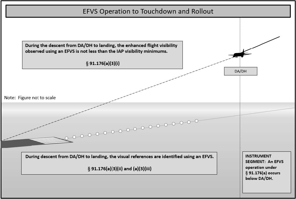
-
EFVS Operations to 100 Feet Above the TDZE. An EFVS operation to 100 feet above the TDZE is an operation in which the pilot uses the enhanced vision imagery provided by an EFVS in lieu of natural vision to descend below DA/DH or MDA down to 100 feet above the TDZE. (See FIG 5-4-33.) To continue the approach below 100 feet above the TDZE, a pilot must have sufficient flight visibility to identify the required visual references using natural vision and must continue to use the EFVS to ensure the enhanced flight visibility meets the visibility requirements of the IAP being flown. These operations may be conducted on SIAPs or special IAPs that have a DA/DH or MDA. An EFVS operation to 100 feet above the TDZE may not be conducted on an approach that has circling minimums. The regulations for EFVS operations to 100 feet above the TDZE can be found in 14 CFR § 91.176(b).
FIG 5-4-33
EFVS Operation to 100 ft Above the TDZE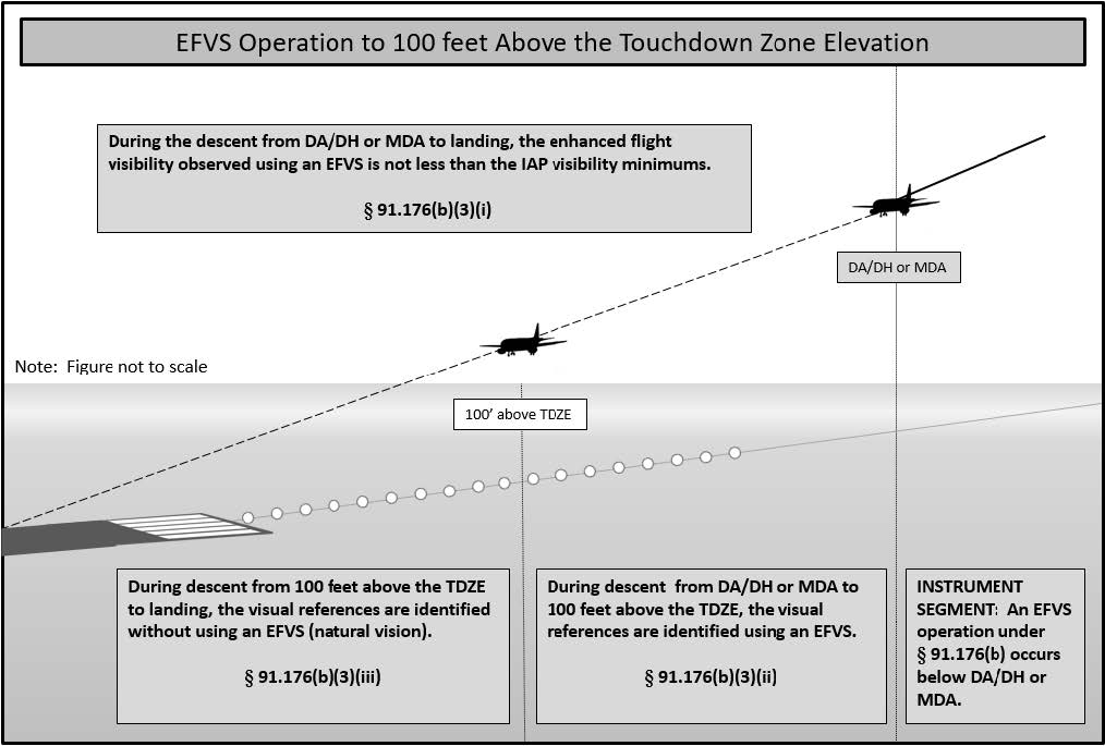
- EFVS Equipment Requirements. An EFVS that is installed on a U.S.-registered aircraft and is used to conduct EFVS operations must conform to an FAA-type design approval (i.e., a type certificate (TC), amended TC, or supplemental type certificate (STC)). A foreign-registered aircraft used to conduct EFVS operations that does not have an FAA-type design approval must be equipped with an EFVS that has been approved by either the State of the Operator or the State of Registry to meet the requirements of ICAO Annex 6. Equipment requirements for an EFVS operation to touchdown and rollout can be found in 14 CFR § 91.176(a)(1), and the equipment requirements for an EFVS operation to 100 feet above the TDZE can be found in 14 CFR § 91.176(b)(1). An operator can determine the eligibility of their aircraft to conduct EFVS operations by referring to the Airplane Flight Manual, Airplane Flight Manual Supplement, Rotorcraft Flight Manual, or Rotorcraft Flight Manual Supplement as applicable.
-
Operating Requirements. Any operator who conducts EFVS operations to touchdown and rollout (14 CFR § 91.176(a)) must have an OpSpec, MSpec, or LOA that specifically authorizes those operations. Parts 91K, 121, 125, 129, and 135 operators who conduct EFVS operations to 100 feet above the TDZE (14 CFR § 91.176(b))must have an OpSpec, MSpec, or LOA that specifically authorizes the operation. Part 91 operators (other than 91K operators) are not required to have an LOA to conduct EFVS operations to 100 feet above the TDZE in the United States. However, an optional LOA is available to facilitate operational approval from foreign Civil Aviation Authorities (CAA). To conduct an EFVS operation to touchdown and rollout during an authorized Category II or III operation, the operator must have:
- An OpSpec, MSpec, or LOA authorizing EFVS operations to touchdown and rollout (14 CFR § 91.176(a)); and
- An OpSpec, MSpec, or LOA authorizing Category II or Category III operations.
- EFVS Operations in Rotorcraft. Currently, EFVS operations in rotorcraft can only be conducted on IAPs that are flown to a runway. Instrument approach criteria, procedures, and appropriate visual references have not yet been developed for straight-in landing operations below DA/DH or MDA under IFR to heliports or platforms. An EFVS cannot be used in lieu of natural vision to descend below published minimums on copter approaches to a point in space (PinS) followed by a “proceed visual flight rules (VFR)” visual segment, or on approaches designed to a specific landing site using a “proceed visually” visual segment.
- EFVS Pilot Requirements. A pilot who conducts EFVS operations must receive ground and flight training specific to the EFVS operation to be conducted. The training must be obtained from an authorized training provider under a training program approved by the FAA. Additionally, recent flight experience and proficiency or competency check requirements apply to EFVS operations. These requirements are addressed in 14 CFR §§ 61.66, 91.1065, 121.441, Appendix F to part 121, 125.287, and 135.293.
- Enhanced Flight Visibility and Visual Reference Requirements. To descend below DA/DH or MDA during EFVS operations under 14 CFR § 91.176(a) or (b), a pilot must make a determination that the enhanced flight visibility observed by using an EFVS is not less than what is prescribed by the IAP being flown. In addition, the visual references required in 14 CFR § 91.176(a) or (b) must be distinctly visible and identifiable to the pilot using the EFVS. The determination of enhanced flight visibility is a separate action from that of identifying required visual references, and is different from ground-reported visibility. Even though the reported visibility or the visibility observed using natural vision may be less, as long as the EFVS provides the required enhanced flight visibility and a pilot meets all of the other requirements, the pilot can continue descending below DA/DH or MDA using the EFVS. Suitable enhanced flight visibility is necessary to ensure the aircraft is in a position to continue the approach and land. It is important to understand that using an EFVS does not result in obtaining lower minima with respect to the visibility or the DA/DH or MDA specified in the IAP. An EFVS simply provides another means of operating in the visual segment of an IAP. The DA/DH or MDA and the visibility value specified in the IAP to be flown do not change.
- Flight Planning and Beginning or Continuing an Approach Under IFR. A part 121, 125, or 135 operator's OpSpec or LOA for EFVS operations may authorize an EFVS operational credit dispatching or releasing a flight and for beginning or continuing an instrument approach procedure. When a pilot reaches DA/DH or MDA, the pilot conducts the EFVS operation in accordance with 14 CFR § 91.176(a) or (b) and their authorization to conduct EFVS operations.
- Missed Approach Considerations. In order to conduct an EFVS operation, the EFVS must be operable. In the event of a failure of any required component of an EFVS at any point in the approach to touchdown, a missed approach is required. However, this provision does not preclude a pilot's authority to continue an approach if continuation of an approach is considered by the pilot to be a safer course of action.
- Light Emitting Diode (LED) Airport Lighting Impact on EFVS Operations. Incandescent lamps are being replaced with LEDs at some airports in threshold lights, taxiway edge lights, taxiway centerline lights, low intensity runway edge lights, wind cone lights, beacons, and some obstruction lighting. Additionally, there are plans to replace incandescent lamps with LEDs in approach lighting systems. Pilots should be aware that LED lights cannot be sensed by infrared-based EFVSs. Airports with LED approach lights will be identified in the Airport Remarks paragraph of the Charting Supplement with the remarks: “Pilots conducting EFVS ops; be aware LED ALS in use.” More information may be found at the FAA Flight Standards EFVS webpage at https://www.faa.gov/about/office_org/headquarters_offices/avs/offices/afx/afs/afs400/afs410/efvs.
- Other Vision Systems. Unlike an EFVS that meets the equipment requirements of 14 CFR § 91.176, a Synthetic Vision System (SVS) or Synthetic Vision Guidance System (SVGS) does not provide a real-time sensor image of the outside scene and also does not meet the equipment requirements for EFVS operations. A pilot cannot use a synthetic vision image on a head-up or a head-down display in lieu of natural vision to descend below DA/DH or MDA. An EFVS can, however, be integrated with an SVS, also known as a Combined Vision System (CVS). A CVS can be used to conduct EFVS operations if all of the requirements for an EFVS are satisfied and the SVS image does not interfere with the pilot's ability to see the external scene, to identify the required visual references, or to see the sensor image.
- Additional Information. Operational criteria for EFVS can be found in Advisory Circular (AC) 90-106, Enhanced Flight Vision System Operations, and airworthiness criteria for EFVS can be found in AC 20-167, Airworthiness Approval of Enhanced Vision System, Synthetic Vision System, Combined Vision System, and Enhanced Flight Vision System Equipment.
-
Introduction. During an instrument approach, an EFVS can enable a pilot to see the approach lights, visual references associated with the runway environment, and other objects or features that might not be visible using natural vision alone. An EFVS uses a head-up display (HUD), or an equivalent display that is a head-up presentation, to combine flight information, flight symbology, navigation guidance, and a real-time image of the external scene to the pilot. Combining the flight information, navigation guidance, and sensor imagery on a HUD (or equivalent display) allows the pilot to continue looking forward along the flightpath throughout the entire approach, landing, and rollout.
-
Visual Approach
- A visual approach is conducted on an IFR flight plan and authorizes a pilot to proceed visually and clear of clouds to the airport. The pilot must have either the airport or the preceding identified aircraft in sight. This approach must be authorized and controlled by the appropriate air traffic control facility. Reported weather at the airport must have a ceiling at or above 1,000 feet and visibility 3 miles or greater. ATC may authorize this type of approach when it will be operationally beneficial. Visual approaches are an IFR procedure conducted under IFR in visual meteorological conditions. Cloud clearance requirements of 14 CFR section 91.155 are not applicable, unless required by operation specifications. When conducting visual approaches, pilots are encouraged to use other available navigational aids to assist in positive lateral and vertical alignment with the runway.
- Operating to an Airport Without Weather Reporting Service. ATC will advise the pilot when weather is not available at the destination airport. ATC may initiate a visual approach provided there is a reasonable assurance that weather at the airport is a ceiling at or above 1,000 feet and visibility 3 miles or greater (e.g., area weather reports, PIREPs, etc.).
-
Operating to an Airport With an Operating Control Tower. Aircraft may be authorized to conduct a visual approach to one runway while other aircraft are conducting IFR or VFR approaches to another parallel, intersecting, or converging runway. ATC may authorize a visual approach after advising all aircraft involved that other aircraft are conducting operations to the other runway. This may be accomplished through use of the ATIS.
- When operating to parallel runways separated by less than 2,500 feet, ATC will ensure approved separation is provided unless the succeeding aircraft reports sighting the preceding aircraft to the adjacent parallel and visual separation is applied.
- When operating to parallel runways separated by at least 2,500 feet but less than 4,300 feet, ATC will ensure approved separation is provided until the aircraft are issued an approach clearance and one pilot has acknowledged receipt of a visual approach clearance, and the other pilot has acknowledged receipt of a visual or instrument approach clearance, and aircraft are established on a heading or established on a direct course to a fix or cleared on an RNAV/instrument approach procedure which will intercept the extended centerline of the runway at an angle not greater than 30 degrees.
-
When operating to parallel runways separated by 4,300 feet or more, ATC will ensure approved separation is provided until one of the aircraft has been issued and the pilot has acknowledged receipt of the visual approach clearance, and each aircraft is assigned a heading, or established on a direct course to a fix, or cleared on an RNAV/instrument approach procedure which will allow the aircraft to intercept the extended centerline of the runway at an angle not greater than 30 degrees.
NOTE-
The intent of the 30 degree intercept angle is to reduce the potential for overshoots of the final and to preclude side-by-side operations with one or both aircraft in a belly-up configuration during the turn-on.
- Clearance for Visual Approach. At locations with an operating control tower, ATC will issue approach clearances that will include an assigned runway. At locations without an operating control tower or where a part-time tower is closed, ATC will issue a visual approach clearance to the airport only.
- Separation Responsibilities. If the pilot has the airport in sight but cannot see the aircraft to be followed, ATC may clear the aircraft for a visual approach; however, ATC retains both separation and wake vortex separation responsibility. When visually following a preceding aircraft, acceptance of the visual approach clearance constitutes acceptance of pilot responsibility for maintaining a safe approach interval and adequate wake turbulence separation.
- A visual approach is not an IAP and therefore has no missed approach segment. If a go-around is necessary for any reason, aircraft operating at controlled airports will be issued an appropriate clearance or instruction by the tower to enter the traffic pattern for landing or proceed as otherwise instructed. In either case, the pilot is responsible to maintain terrain and obstruction avoidance until reaching an ATC assigned altitude if issued, and ATC will provide approved separation or visual separation from other IFR aircraft. At uncontrolled airports, aircraft are expected to remain clear of clouds and complete a landing as soon as possible. If a landing cannot be accomplished, the aircraft is expected to remain clear of clouds and contact ATC as soon as possible for further clearance. Separation from other IFR aircraft will be maintained under these circumstances.
- Visual approaches reduce pilot/controller workload and expedite traffic by shortening flight paths to the airport. It is the pilot's responsibility to advise ATC as soon as possible if a visual approach is not desired.
-
Authorization to conduct a visual approach is an IFR authorization and does not alter IFR flight plan cancellation responsibility.
REFERENCE-
AIM, Para 5-1-15, Canceling IFR Flight Plan.
- Radar service is automatically terminated, without advising the pilot, when the aircraft is instructed to change to advisory frequency.
-
Charted Visual Flight Procedure (CVFP)
- CVFPs are charted visual approaches established for environmental/noise considerations, and/or when necessary for the safety and efficiency of air traffic operations. The approach charts depict prominent landmarks, courses, and recommended altitudes to specific runways. CVFPs are designed to be used primarily for turbojet aircraft.
- These procedures will be used only at airports with an operating control tower.
- Most approach charts will depict some NAVAID information which is for supplemental navigational guidance only.
- Unless indicating a Class B airspace floor, all depicted altitudes are for noise abatement purposes and are recommended only. Pilots are not prohibited from flying other than recommended altitudes if operational requirements dictate.
- When landmarks used for navigation are not visible at night, the approach will be annotated “PROCEDURE NOT AUTHORIZED AT NIGHT.”
- CVFPs usually begin within 20 flying miles from the airport.
- Published weather minimums for CVFPs are based on minimum vectoring altitudes rather than the recommended altitudes depicted on charts.
- CVFPs are not instrument approaches and do not have missed approach segments.
- ATC will not issue clearances for CVFPs when the weather is less than the published minimum.
- ATC will clear aircraft for a CVFP after the pilot reports siting a charted landmark or a preceding aircraft. If instructed to follow a preceding aircraft, pilots are responsible for maintaining a safe approach interval and wake turbulence separation.
- Pilots should advise ATC if at any point they are unable to continue an approach or lose sight of a preceding aircraft. Missed approaches will be handled as a go-around.
- When conducting visual approaches, pilots are encouraged to use other available navigational aids to assist in positive lateral and vertical alignment with the assigned runway.
-
Contact Approach
- Pilots operating in accordance with an IFR flight plan, provided they are clear of clouds and have at least 1 mile flight visibility and can reasonably expect to continue to the destination airport in those conditions, may request ATC authorization for a contact approach.
-
Controllers may authorize a contact approach provided:
-
The contact approach is specifically requested by the pilot. ATC cannot initiate this approach.
EXAMPLE-
Request contact approach.
- The reported ground visibility at the destination airport is at least 1 statute mile.
- The contact approach will be made to an airport having a standard or special instrument approach procedure.
-
Approved separation is applied between aircraft so cleared and between these aircraft and other IFR or special VFR aircraft.
EXAMPLE-
Cleared contact approach (and, if required) at or below (altitude) (routing) if not possible (alternative procedures) and advise.
-
The contact approach is specifically requested by the pilot. ATC cannot initiate this approach.
- A contact approach is an approach procedure that may be used by a pilot (with prior authorization from ATC) in lieu of conducting a standard or special IAP to an airport. It is not intended for use by a pilot on an IFR flight clearance to operate to an airport not having a published and functioning IAP. Nor is it intended for an aircraft to conduct an instrument approach to one airport and then, when “in the clear,” discontinue that approach and proceed to another airport. In the execution of a contact approach, the pilot assumes the responsibility for obstruction clearance. If radar service is being received, it will automatically terminate when the pilot is instructed to change to advisory frequency.
-
Landing Priority
A clearance for a specific type of approach (ILS, RNAV, GLS, ADF, VOR or Visual Approach) to an aircraft operating on an IFR flight plan does not mean that landing priority will be given over other traffic. ATCTs handle all aircraft, regardless of the type of flight plan, on a “first-come, first-served” basis. Therefore, because of local traffic or runway in use, it may be necessary for the controller in the interest of safety, to provide a different landing sequence. In any case, a landing sequence will be issued to each aircraft as soon as possible to enable the pilot to properly adjust the aircraft's flight path.
-
Overhead Approach Maneuver
-
Pilots operating in accordance with an IFR flight plan in Visual Meteorological Conditions (VMC) may request ATC authorization for an overhead maneuver. An overhead maneuver is not an instrument approach procedure. Overhead maneuver patterns are developed at airports where aircraft have an operational need to conduct the maneuver. An aircraft conducting an overhead maneuver is considered to be VFR and the IFR flight plan is canceled when the aircraft reaches the initial point on the initial approach portion of the maneuver. (See FIG 5-4-34.) The existence of a standard overhead maneuver pattern does not eliminate the possible requirement for an aircraft to conform to conventional rectangular patterns if an overhead maneuver cannot be approved. Aircraft operating to an airport without a functioning control tower must initiate cancellation of an IFR flight plan prior to executing the overhead maneuver. Cancellation of the IFR flight plan must be accomplished after crossing the landing threshold on the initial portion of the maneuver or after landing. Controllers may authorize an overhead maneuver and issue the following to arriving aircraft:
-
Pattern altitude and direction of traffic. This information may be omitted if either is standard.
PHRASEOLOGY-
PATTERN ALTITUDE (altitude). RIGHT TURNS.
-
Request for a report on initial approach.
PHRASEOLOGY-
REPORT INITIAL.
-
“Break” information and a request for the pilot to report. The “Break Point” will be specified if nonstandard. Pilots may be requested to report “break” if required for traffic or other reasons.
PHRASEOLOGY-
BREAK AT (specified point).
REPORT BREAK.FIG 5-4-34
Overhead Maneuver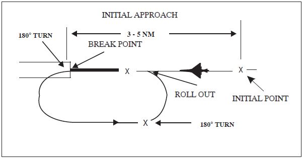
-
Pattern altitude and direction of traffic. This information may be omitted if either is standard.
-
Pilots operating in accordance with an IFR flight plan in Visual Meteorological Conditions (VMC) may request ATC authorization for an overhead maneuver. An overhead maneuver is not an instrument approach procedure. Overhead maneuver patterns are developed at airports where aircraft have an operational need to conduct the maneuver. An aircraft conducting an overhead maneuver is considered to be VFR and the IFR flight plan is canceled when the aircraft reaches the initial point on the initial approach portion of the maneuver. (See FIG 5-4-34.) The existence of a standard overhead maneuver pattern does not eliminate the possible requirement for an aircraft to conform to conventional rectangular patterns if an overhead maneuver cannot be approved. Aircraft operating to an airport without a functioning control tower must initiate cancellation of an IFR flight plan prior to executing the overhead maneuver. Cancellation of the IFR flight plan must be accomplished after crossing the landing threshold on the initial portion of the maneuver or after landing. Controllers may authorize an overhead maneuver and issue the following to arriving aircraft:
Section 5. Pilot/Controller Roles and Responsibilities
-
General
- The roles and responsibilities of the pilot and controller for effective participation in the ATC system are contained in several documents. Pilot responsibilities are in the CFRs and the air traffic controllers' are in the FAA Order JO 7110.65, Air Traffic Control, and supplemental FAA directives. Additional and supplemental information for pilots can be found in the current Aeronautical Information Manual (AIM), Notices to Airmen, Advisory Circulars and aeronautical charts. Since there are many other excellent publications produced by nongovernment organizations, as well as other government organizations, with various updating cycles, questions concerning the latest or most current material can be resolved by cross‐checking with the above mentioned documents.
- The pilot-in-command of an aircraft is directly responsible for, and is the final authority as to the safe operation of that aircraft. In an emergency requiring immediate action, the pilot-in-command may deviate from any rule in the General Subpart A and Flight Rules Subpart B in accordance with 14 CFR section 91.3.
- The air traffic controller is responsible to give first priority to the separation of aircraft and to the issuance of radar safety alerts, second priority to other services that are required, but do not involve separation of aircraft and third priority to additional services to the extent possible.
- In order to maintain a safe and efficient air traffic system, it is necessary that each party fulfill their responsibilities to the fullest.
- The responsibilities of the pilot and the controller intentionally overlap in many areas providing a degree of redundancy. Should one or the other fail in any manner, this overlapping responsibility is expected to compensate, in many cases, for failures that may affect safety.
- The following, while not intended to be all inclusive, is a brief listing of pilot and controller responsibilities for some commonly used procedures or phases of flight. More detailed explanations are contained in other portions of this publication, the appropriate CFRs, ACs and similar publications. The information provided is an overview of the principles involved and is not meant as an interpretation of the rules nor is it intended to extend or diminish responsibilities.
-
Air Traffic Clearance
-
Pilot.
- Acknowledges receipt and understanding of an ATC clearance.
- Reads back any hold short of runway instructions issued by ATC.
- Requests clarification or amendment, as appropriate, any time a clearance is not fully understood or considered unacceptable from a safety standpoint.
-
Promptly complies with an air traffic clearance upon receipt except as necessary to cope with an emergency. Advises ATC as soon as possible and obtains an amended clearance, if deviation is necessary.
NOTE-
A clearance to land means that appropriate separation on the landing runway will be ensured. A landing clearance does not relieve the pilot from compliance with any previously issued altitude crossing restriction.
-
Controller.
- Issues appropriate clearances for the operation to be conducted, or being conducted, in accordance with established criteria.
- Assigns altitudes in IFR clearances that are at or above the minimum IFR altitudes in controlled airspace.
- Ensures acknowledgement by the pilot for issued information, clearances, or instructions.
- Ensures that readbacks by the pilot of altitude, heading, or other items are correct. If incorrect, distorted, or incomplete, makes corrections as appropriate.
-
Pilot.
-
Contact Approach
-
Pilot.
- Must request a contact approach and makes it in lieu of a standard or special instrument approach.
- By requesting the contact approach, indicates that the flight is operating clear of clouds, has at least one mile flight visibility, and reasonably expects to continue to the destination airport in those conditions.
- Assumes responsibility for obstruction clearance while conducting a contact approach.
- Advises ATC immediately if unable to continue the contact approach or if encounters less than 1 mile flight visibility.
-
Is aware that if radar service is being received, it may be automatically terminated when told to contact the tower.
REFERENCE-
P/CG Term - RADAR SERVICE TERMINATED.
-
Controller.
- Issues clearance for a contact approach only when requested by the pilot. Does not solicit the use of this procedure.
- Before issuing the clearance, ascertains that reported ground visibility at destination airport is at least 1 mile.
- Provides approved separation between the aircraft cleared for a contact approach and other IFR or special VFR aircraft. When using vertical separation, does not assign a fixed altitude, but clears the aircraft at or below an altitude which is at least 1,000 feet below any IFR traffic but not below Minimum Safe Altitudes prescribed in 14 CFR section 91.119.
- Issues alternative instructions if, in their judgment, weather conditions may make completion of the approach impracticable.
-
Pilot.
-
Instrument Approach
-
Pilot.
- Be aware that the controller issues clearance for approach based only on known traffic.
-
Follows the procedure as shown on the IAP, including all restrictive notations, such as:
- Procedure not authorized at night;
- Approach not authorized when local area altimeter not available;
- Procedure not authorized when control tower not in operation;
- Procedure not authorized when glide slope not used;
- Straight‐in minimums not authorized at night; etc.
- Radar required; or
-
The circling minimums published on the instrument approach chart provide adequate obstruction clearance and pilots should not descend below the circling altitude until the aircraft is in a position to make final descent for landing. Sound judgment and knowledge of the pilot's and the aircraft's capabilities are the criteria for determining the exact maneuver in each instance since airport design and the aircraft position, altitude and airspeed must all be considered.
REFERENCE-
AIM, Para 5-4-20, Approach and Landing Minimums.
-
Upon receipt of an approach clearance while on an unpublished route or being radar vectored:
- Complies with the minimum altitude for IFR; and
- Maintains the last assigned altitude until established on a segment of a published route or IAP, at which time published altitudes apply.
-
There are currently two temperature limitations that may be published in the notes box of the middle briefing strip on an instrument approach procedure (IAP). The two published temperature limitations are:
- A temperature range limitation associated with the use of baro-VNAV that may be published on a United States PBN IAP titled RNAV (GPS) or RNAV (RNP); and/or
- A Cold Temperature Airport (CTA) limitation designated by a snowflake ICON and temperature in Celsius (C) that is published on every IAP for the airfield.
-
Any planned altitude correction for the intermediate and/or missed approach holding segments must be coordinated with ATC. Pilots do not have to advise ATC of a correction in the final segment.
REFERENCE-
AIM, Chapter 7, Section 3, Cold Temperature Barometric Altimeter Errors, Setting Procedures, and Cold Temperature Airports (CTA).
-
Controller.
- Issues an approach clearance based on known traffic.
- Issues an IFR approach clearance only after the aircraft is established on a segment of published route or IAP, or assigns an appropriate altitude for the aircraft to maintain until so established.
-
Pilot.
-
Missed Approach
-
Pilot.
- Executes a missed approach when one of the following conditions exist:
- Advises ATC that a missed approach will be made. Include the reason for the missed approach unless the missed approach is initiated by ATC.
- Complies with the missed approach instructions for the IAP being executed from the MAP, unless other missed approach instructions are specified by ATC.
- If executing a missed approach prior to reaching the MAP, fly the lateral navigation path of the instrument procedure to the MAP. Climb to the altitude specified in the missed approach procedure, except when a maximum altitude is specified between the final approach fix (FAF) and the MAP. In that case, comply with the maximum altitude restriction. Note, this may require a continued descent on the final approach.
-
Cold Temperature Airports (CTA) are designated by a snowflake ICON and temperature in Celsius (C) that are published in the notes box of the middle briefing strip on an instrument approach procedure (IAP). Pilots should apply a cold temperature correction to the missed approach final holding altitude when the reported temperature is at or below the CTA temperature limitation. Pilots must inform ATC of the correction.
REFERENCE-
AIM, Chapter 7, Section 3, Cold Temperature Barometric Altimeter Errors, Setting Procedures, and Cold Temperature Airports (CTA).
- Following a missed approach, requests clearance for specific action; i.e., another approach, hold for improved conditions, proceed to an alternate airport, etc.
-
Controller.
- Issues an approved alternate missed approach procedure if it is desired that the pilot execute a procedure other than as depicted on the instrument approach chart.
- May vector a radar identified aircraft executing a missed approach when operationally advantageous to the pilot or the controller.
- In response to the pilot's stated intentions, issues a clearance to an alternate airport, to a holding fix, or for reentry into the approach sequence, as traffic conditions permit.
-
Pilot.
-
Vectors
-
Pilot.
- Promptly complies with headings and altitudes assigned to you by the controller.
- Questions any assigned heading or altitude believed to be incorrect.
- If operating VFR and compliance with any radar vector or altitude would cause a violation of any CFR, advises ATC and obtains a revised clearance or instructions.
-
Controller.
-
Vectors aircraft in Class A, Class B, Class C, Class D, and Class E airspace:
- For separation.
- For noise abatement.
- To obtain an operational advantage for the pilot or controller.
- Vectors aircraft in Class A, Class B, Class C, Class D, Class E, and Class G airspace when requested by the pilot.
- Except where authorized for radar approaches, radar departures, special VFR, or when operating in accordance with vectors below minimum altitude procedures, vector IFR aircraft at or above minimum vectoring altitudes.
- May vector aircraft off assigned procedures. When published altitude or speed restrictions are included, controllers must assign an altitude, or if necessary, a speed.
- May vector VFR aircraft, not at an ATC assigned altitude, at any altitude. In these cases, terrain separation is the pilot's responsibility.
-
Vectors aircraft in Class A, Class B, Class C, Class D, and Class E airspace:
-
Pilot.
-
Safety Alert
-
Pilot.
- Initiates appropriate action if a safety alert is received from ATC.
- Be aware that this service is not always available and that many factors affect the ability of the controller to be aware of a situation in which unsafe proximity to terrain, obstructions, or another aircraft may be developing.
-
Controller.
-
Issues a safety alert if aware an aircraft under their control is at an altitude which, in the controller's judgment, places the aircraft in unsafe proximity to terrain, obstructions or another aircraft. Types of safety alerts are:
- Terrain or Obstruction Alert.Immediately issued to an aircraft under their control if aware the aircraft is at an altitude believed to place the aircraft in unsafe proximity to terrain or obstructions.
- Aircraft Conflict Alert.Immediately issued to an aircraft under their control if aware of an aircraft not under their control at an altitude believed to place the aircraft in unsafe proximity to each other. With the alert, they offer the pilot an alternative, if feasible.
- Discontinue further alerts if informed by the pilot action is being taken to correct the situation or that the other aircraft is in sight.
-
Issues a safety alert if aware an aircraft under their control is at an altitude which, in the controller's judgment, places the aircraft in unsafe proximity to terrain, obstructions or another aircraft. Types of safety alerts are:
-
Pilot.
-
See and Avoid
- Pilot. When meteorological conditions permit, regardless of type of flight plan or whether or not under control of a radar facility, the pilot is responsible to see and avoid other traffic, terrain, or obstacles.
-
Controller.
- Provides radar traffic information to radar identified aircraft operating outside positive control airspace on a workload permitting basis.
- Issues safety alerts to aircraft under their control if aware the aircraft is at an altitude believed to place the aircraft in unsafe proximity to terrain, obstructions, or other aircraft.
-
Speed Adjustments
-
Pilot.
- Advises ATC any time cruising airspeed varies plus or minus 5 percent or 10 knots, whichever is greater, from that given in the flight plan.
-
Complies with speed adjustments from ATC unless:
-
The minimum or maximum safe airspeed for any particular operation is greater or less than the requested airspeed. In such cases, advises ATC.
NOTE-
It is the pilot's responsibility and prerogative to refuse speed adjustments considered excessive or contrary to the aircraft's operating specifications.
- Operating at or above 10,000 feet MSL on an ATC assigned SPEED ADJUSTMENT of more than 250 knots IAS and subsequent clearance is received for descent below 10,000 feet MSL. In such cases, pilots are expected to comply with 14 CFR section 91.117(a).
-
The minimum or maximum safe airspeed for any particular operation is greater or less than the requested airspeed. In such cases, advises ATC.
- When complying with speed adjustment assignments, maintains an indicated airspeed within plus or minus 10 knots or 0.02 Mach number of the specified speed.
-
Controller.
- Assigns speed adjustments to aircraft when necessary but not as a substitute for good vectoring technique.
- Adheres to the restrictions published in FAA Order JO 7110.65, Air Traffic Control, as to when speed adjustment procedures may be applied.
- Avoids speed adjustments requiring alternate decreases and increases.
- Assigns speed adjustments to a specified IAS (KNOTS)/Mach number or to increase or decrease speed using increments of 5 knots or multiples thereof.
-
Terminates ATC-assigned speed adjustments when no longer required by issuing further instructions to pilots in the following manner:
- Advises pilots to “resume normal speed” when the aircraft is on a heading, random routing, charted procedure, or route without published speed restrictions.
-
Instructs pilots to “comply with speed restrictions” when the aircraft is joining or resuming a charted procedure or route with published speed restrictions.
CAUTION-
The phraseology “Climb via SID” requires compliance with all altitude and/or speed restrictions depicted on the procedure.
- Instructs pilots to “resume published speed” when aircraft are cleared via a charted instrument flight procedure that contains published speed restrictions.
- Advises aircraft to “delete speed restrictions” when ATC assigned or published speed restrictions on a charted procedure are no longer required.
-
Clears pilots for approach without restating previously issued speed adjustments.
REFERENCE-
Pilot/Controller Glossary Term - Resume Normal Speed.
Pilot/Controller Glossary Term - Resume Published Speed.
- Gives due consideration to aircraft capabilities to reduce speed while descending.
- Does not assign speed adjustments to aircraft at or above FL 390 without pilot consent.
-
Pilot.
-
Traffic Advisories (Traffic Information)
-
Pilot.
- Acknowledges receipt of traffic advisories.
- Informs controller if traffic in sight.
- Advises ATC if a vector to avoid traffic is desired.
- Does not expect to receive radar traffic advisories on all traffic. Some aircraft may not appear on the radar display. Be aware that the controller may be occupied with higher priority duties and unable to issue traffic information for a variety of reasons.
- Advises controller if service is not desired.
-
Controller.
- Issues radar traffic to the maximum extent consistent with higher priority duties except in Class A airspace.
- Provides vectors to assist aircraft to avoid observed traffic when requested by the pilot.
- Issues traffic information to aircraft in the Class B, Class C, and Class D surface areas for sequencing purposes.
- Controllers are required to issue traffic advisories to each aircraft operating on intersecting or nonintersecting converging runways where projected flight paths will cross.
-
Pilot.
-
Visual Approach
-
Pilot.
- If a visual approach is not desired, advises ATC.
- Complies with controller's instructions for vectors toward the airport of intended landing or to a visual position behind a preceding aircraft.
- The pilot must, at all times, have either the airport or the preceding aircraft in sight. After being cleared for a visual approach, proceed to the airport in a normal manner or follow the preceding aircraft. Remain clear of clouds while conducting a visual approach.
- If the pilot accepts a visual approach clearance to visually follow a preceding aircraft, you are required to establish a safe landing interval behind the aircraft you were instructed to follow. You are responsible for wake turbulence separation.
- Advise ATC immediately if the pilot is unable to continue following the preceding aircraft, cannot remain clear of clouds, needs to climb, or loses sight of the airport.
- In the event of a go-around, the pilot is responsible to maintain terrain and obstruction avoidance until reaching an ATC assigned altitude if issued.
- Be aware that radar service is automatically terminated, without being advised by ATC, when the pilot is instructed to change to advisory frequency.
- Be aware that there may be other traffic in the traffic pattern and the landing sequence may differ from the traffic sequence assigned by approach control or ARTCC.
-
Controller.
- Do not clear an aircraft for a visual approach unless reported weather at the airport is ceiling at or above 1,000 feet and visibility is 3 miles or greater. When weather is not available for the destination airport, inform the pilot and do not initiate a visual approach to that airport unless there is reasonable assurance that descent and flight to the airport can be made visually.
- Issue visual approach clearance when the pilot reports sighting either the airport or a preceding aircraft which is to be followed.
- Provide separation except when visual separation is being applied by the pilot.
- Continue flight following and traffic information until the aircraft has landed or has been instructed to change to advisory frequency.
- For all aircraft, inform the pilot when the preceding aircraft is a heavy. Inform the pilot of a small aircraft when the preceding aircraft is a B757. Visual separation is prohibited behind super aircraft.
- When weather is available for the destination airport, do not initiate a vector for a visual approach unless the reported ceiling at the airport is 500 feet or more above the MVA and visibility is 3 miles or more. If vectoring weather minima are not available but weather at the airport is ceiling at or above 1,000 feet and visibility of 3 miles or greater, visual approaches may still be conducted.
-
Pilot.
-
Visual Separation
-
Pilot.
- Acceptance of instructions to follow another aircraft or to provide visual separation from it is an acknowledgment that the pilot will maneuver the aircraft as necessary to avoid the other aircraft or to maintain in‐trail separation. Pilots are responsible to maintain visual separation until flight paths (altitudes and/or courses) diverge.
- If instructed by ATC to follow another aircraft or to provide visual separation from it, promptly notify the controller if you lose sight of that aircraft, are unable to maintain continued visual contact with it, or cannot accept the responsibility for your own separation for any reason.
- The pilot also accepts responsibility for wake turbulence separation under these conditions.
-
Controller. Applies visual separation only:
- Within the terminal area when a controller has both aircraft in sight or by instructing a pilot who sees the other aircraft to maintain visual separation from it.
- Pilots are responsible to maintain visual separation until flight paths (altitudes and/or courses) diverge.
- Within en route airspace when aircraft are on opposite courses and one pilot reports having seen the other aircraft and that the aircraft have passed each other.
-
Pilot.
-
VFR‐on‐top
-
Pilot.
-
This clearance must be requested by the pilot on an IFR flight plan, and if approved, allows the pilot the choice (subject to any ATC restrictions) to select an altitude or flight level in lieu of an assigned altitude.
NOTE-
VFR-on-top is not permitted in certain airspace areas, such as Class A airspace, certain restricted areas, etc. Consequently, IFR flights operating VFR-on-top will avoid such airspace.
REFERENCE-
AIM, Para 4-4-8, IFR Clearance VFR-on-top.
AIM, Para 4-4-11, IFR Separation Standards.
AIM, Para 5-3-2, Position Reporting.
AIM, Para 5-3-3, Additional Reports. -
By requesting a VFR‐on‐top clearance, the pilot assumes the sole responsibility to be vigilant so as to see and avoid other aircraft and to:
- Fly at the appropriate VFR altitude as prescribed in 14 CFR section 91.159.
- Comply with the VFR visibility and distance from clouds criteria in 14 CFR section 91.155, Basic VFR Weather Minimums.
- Comply with instrument flight rules that are applicable to this flight; i.e., minimum IFR altitudes, position reporting, radio communications, course to be flown, adherence to ATC clearance, etc.
- Should advise ATC prior to any altitude change to ensure the exchange of accurate traffic information.
-
This clearance must be requested by the pilot on an IFR flight plan, and if approved, allows the pilot the choice (subject to any ATC restrictions) to select an altitude or flight level in lieu of an assigned altitude.
-
Controller.
- May clear an aircraft to maintain VFR‐on‐top if the pilot of an aircraft on an IFR flight plan requests the clearance.
- Informs the pilot of an aircraft cleared to climb to VFR‐on‐top the reported height of the tops or that no top report is available; issues an alternate clearance if necessary; and once the aircraft reports reaching VFR‐on‐top, reclears the aircraft to maintain VFR‐on‐top.
- Before issuing clearance, ascertain that the aircraft is not in or will not enter Class A airspace.
-
Pilot.
-
Instrument Departures
-
Pilot.
- Prior to departure considers the type of terrain and other obstructions on or in the vicinity of the departure airport.
- Determines if obstruction avoidance can be maintained visually or that the departure procedure should be followed.
- Determines whether an obstacle departure procedure (ODP) and/or DP is available for obstruction avoidance. One option may be a Visual Climb Over Airport (VCOA). Pilots must advise ATC as early as possible of the intent to fly the VCOA prior to departure.
- At airports where IAPs have not been published, hence no published departure procedure, determines what action will be necessary and takes such action that will assure a safe departure.
-
Controller.
- At locations with airport traffic control service, when necessary, specifies direction of takeoff, turn, or initial heading to be flown after takeoff, consistent with published departure procedures (DP) or diverse vector areas (DVA), where applicable.
- At locations without airport traffic control service but within Class E surface area when necessary to specify direction of takeoff, turn, or initial heading to be flown, obtains pilot's concurrence that the procedure will allow the pilot to comply with local traffic patterns, terrain, and obstruction avoidance.
- When the initial heading will take the aircraft off an assigned procedure (for example, an RNAV SID with a published lateral path to a waypoint and crossing restrictions from the departure end of runway), the controller will assign an altitude to maintain with the initial heading.
- Includes established departure procedures as part of the ATC clearance when pilot compliance is necessary to ensure separation.
- At locations with both SIDs and DVAs, ATC will provide an amended departure clearance to cancel a previously assigned SID and subsequently utilize a DVA or vice versa. The amended clearance will be provided to the pilot in a timely manner so that the pilot may confirm adequate climb performance exists to determine if the amended clearance is acceptable, and brief the changes in advance of entering the runway.
- At locations with a DVA, ATC is not permitted to utilize a SID and DVA concurrently.
-
Pilot.
-
Minimum Fuel Advisory
-
Pilot.
- Advise ATC of your minimum fuel status when your fuel supply has reached a state where, upon reaching destination, you cannot accept any undue delay.
- Be aware this is not an emergency situation, but merely an advisory that indicates an emergency situation is possible should any undue delay occur.
-
On initial contact the term “minimum fuel” should be used after stating call sign.
EXAMPLE-
Salt Lake Approach, United 621, “minimum fuel.”
- Be aware a minimum fuel advisory does not imply a need for traffic priority.
-
If the remaining usable fuel supply suggests the need for traffic priority to ensure a safe landing, you should declare an emergency due to low fuel and report fuel remaining in minutes.
REFERENCE-
P/CG Term - FUEL REMAINING.
-
Controller.
- When an aircraft declares a state of minimum fuel, relay this information to the facility to whom control jurisdiction is transferred.
- Be alert for any occurrence which might delay the aircraft.
-
Pilot.
-
RNAV and RNP Operations
-
Pilot.
- If unable to comply with the requirements of an RNAV or RNP procedure, pilots must advise air traffic control as soon as possible. For example, “N1234, failure of GPS system, unable RNAV, request amended clearance.”
- Pilots are not authorized to fly a published RNAV or RNP procedure (instrument approach, departure, or arrival procedure) unless it is retrievable by the procedure name from the current aircraft navigation database and conforms to the charted procedure. The system must be able to retrieve the procedure by name from the aircraft navigation database, not just as a manually entered series of waypoints.
- Whenever possible, RNAV routes (Q- or T-route) should be extracted from the database in their entirety, rather than loading RNAV route waypoints from the database into the flight plan individually. However, selecting and inserting individual, named fixes from the database is permitted, provided all fixes along the published route to be flown are inserted.
-
Pilots must not change any database waypoint type from a fly-by to fly-over, or vice versa. No other modification of database waypoints or the creation of user-defined waypoints on published RNAV or RNP procedures is permitted, except to:
- Change altitude and/or airspeed waypoint constraints to comply with an ATC clearance/instruction.
- Insert a waypoint along the published route to assist in complying with ATC instruction, example, “Descend via the WILMS arrival except cross 30 north of BRUCE at/or below FL 210.” This is limited only to systems that allow along-track waypoint construction.
- Pilots of FMS-equipped aircraft, who are assigned an RNAV DP or STAR procedure and subsequently receive a change of runway, transition or procedure, must verify that the appropriate changes are loaded and available for navigation.
- For RNAV 1 DPs and STARs, pilots must use a CDI, flight director and/or autopilot, in lateral navigation mode. Other methods providing an equivalent level of performance may also be acceptable.
- For RNAV 1 DPs and STARs, pilots of aircraft without GPS, using DME/DME/IRU, must ensure the aircraft navigation system position is confirmed, within 1,000 feet, at the start point of take-off roll. The use of an automatic or manual runway update is an acceptable means of compliance with this requirement. Other methods providing an equivalent level of performance may also be acceptable.
- For procedures or routes requiring the use of GPS, if the navigation system does not automatically alert the flight crew of a loss of GPS, the operator must develop procedures to verify correct GPS operation.
- RNAV terminal procedures (DP and STAR) may be amended by ATC issuing radar vectors and/or clearances direct to a waypoint. Pilots should avoid premature manual deletion of waypoints from their active “legs” page to allow for rejoining procedures.
-
RAIM Prediction: If TSO-C129 equipment is used to solely satisfy the RNAV and RNP requirement, GPS RAIM availability must be confirmed for the intended route of flight (route and time). If RAIM is not available, pilots need an approved alternate means of navigation.
REFERENCE-
AIM, Para 5-1-16, RNAV and RNP Operations.
-
Definition of “established” for RNAV and RNP operations. An aircraft is considered to be established on-course during RNAV and RNP operations anytime it is within 1 times the required accuracy for the segment being flown. For example, while operating on a Q-Route (RNAV 2), the aircraft is considered to be established on-course when it is within 2 NM of the course centerline.
NOTE-
- Pilots must be aware of how their navigation system operates, along with any AFM limitations, and confirm that the aircraft's lateral deviation display (or map display if being used as an allowed alternate means) is suitable for the accuracy of the segment being flown. Automatic scaling and alerting changes are appropriate for some operations. For example, TSO-C129 systems change within 30 miles of destination and within 2 miles of FAF to support approach operations. For some navigation systems and operations, manual selection of scaling will be necessary.
- Pilots flying FMS equipped aircraft with barometric vertical navigation (Baro-VNAV) may descend when the aircraft is established on-course following FMS leg transition to the next segment. Leg transition normally occurs at the turn bisector for a fly-by waypoint (reference paragraph 1-2-1 for more on waypoints). When using full automation, pilots should monitor the aircraft to ensure the aircraft is turning at appropriate lead times and descending once established on-course.
- Pilots flying TSO-C129 navigation system equipped aircraft without full automation should use normal lead points to begin the turn. Pilots may descend when established on-course on the next segment of the approach.
-
Pilot.
Section 6. National Security and Interception Procedures
-
National Security
National security in the control of air traffic is governed by 14 Code of Federal Regulations (CFR) part 99, Security Control of Air Traffic.
-
National Security Requirements
- Pursuant to 14 CFR 99.7, Special Security Instructions, each person operating an aircraft in an Air Defense Identification Zone (ADIZ) or Defense Area must, in addition to the applicable rules of part 99, comply with special security instructions issued by the FAA Administrator in the interest of national security, pursuant to agreement between the FAA and the Department of Defense (DoD), or between the FAA and a U.S. Federal security or intelligence agency.
- In addition to the requirements prescribed in this section, national security requirements for aircraft operations to or from, within, or transiting U.S. territorial airspace are in effect pursuant to 14 CFR 99.7; 49 United States Code (USC) 40103, Sovereignty and Use of Airspace; and 49 USC 41703, Navigation of Foreign Civil Aircraft. Aircraft operations to or from, within, or transiting U.S. territorial airspace must also comply with all other applicable regulations published in 14 CFR.
-
Due to increased security measures in place at many areas and in accordance with 14 CFR 91.103, Preflight Action, prior to departure, pilots must become familiar with all available information concerning that flight. Pilots are responsible to comply with 14 CFR 91.137 (Temporary flight restrictions in the vicinity of disaster/hazard areas), 91.138 (Temporary flight restrictions in national disaster areas in the State of Hawaii), 91.141 (Flight restrictions in the proximity of the Presidential and other parties), and 91.143 (Flight limitation in the proximity of space flight operations) when conducting flight in an area where a temporary flight restrictions area is in effect, and should check appropriate NOTAMs during flight planning. In addition, NOTAMs may be issued for National Security Areas (NSA) that temporarily prohibit flight operations under the provisions of 14 CFR 99.7.
REFERENCE-
AIM, Para 3-4-8, National Security Areas.
AIM, Para 3-5-3, Temporary Flight Restrictions. - Noncompliance with the national security requirements for aircraft operations contained in this section may result in denial of flight entry into U.S. territorial airspace or ground stop of the flight at a U.S. airport.
- Pilots of aircraft that do not adhere to the procedures in the national security requirements for aircraft operations contained in this section may be intercepted, and/or detained and interviewed by federal, state, or local law enforcement or other government personnel.
-
Definitions
- Air Defense Identification Zone (ADIZ) means an area of airspace over land or water, in which the ready identification, location, and control of all aircraft (except Department of Defense and law enforcement aircraft) is required in the interest of national security.
- Defense Area means any airspace of the contiguous U.S. that is not an ADIZ in which the control of aircraft is required for reasons of national security.
- U.S. territorial airspace, for the purposes of this section,means the airspace over the U.S., its territories, and possessions, and the airspace over the territorial sea of the U.S., which extends 12 nautical miles from the baselines of the U.S., determined in accordance with international law.
- To U.S. territorial airspace means any flight that enters U.S. territorial airspace after departure from a location outside of the U.S., its territories or possessions, for landing at a destination in the U.S., its territories or possessions.
- From U.S. territorial airspace means any flight that exits U.S. territorial airspace after departure from a location in the U.S., its territories or possessions, and lands at a destination outside the U.S., its territories or possessions.
- Within U.S. territorial airspace means any flight departing from a location inside of the U.S., its territories or possessions, which operates en route to a location inside the U.S., its territories or possessions.
- Transit or transiting U.S. territorial airspace means any flight departing from a location outside of the U.S., its territories or possessions, which operates in U.S. territorial airspace en route to a location outside the U.S., its territories or possessions without landing at a destination in the U.S., its territories or possessions.
- Aeronautical facility, for the purposes of this section, means a communications facility where flight plans or position reports are normally filed during flight operations.
-
ADIZ Requirements
- To facilitate early identification of all aircraft in the vicinity of U.S. airspace boundaries, Air Defense Identification Zones (ADIZ) have been established. All aircraft must meet certain requirements to facilitate early identification when operating into, within, and across an ADIZ, as described in 14 CFR 99.
-
Requirements for aircraft operations are as follows:
-
Transponder Requirements. Unless otherwise authorized by ATC, each aircraft conducting operations into, within, or across the contiguous U.S. ADIZ must be equipped with an operable radar beacon transponder. The transponder must be turned on and squawking a discrete beacon code assigned by ATC or issued by FSS and displaying the aircraft altitude. Use of beacon code 1200 is not authorized. Use of the Universal Access Transceiver (UAT) anonymity mode is not authorized.
- For air defense purposes, aircraft equipped with an operable 1090es (DO-260b) ADS-B system operating outbound across the contiguous U.S. ADIZ may also be identified by the ICAO aircraft address (otherwise known as the aircraft Mode S code). Therefore, use of a privacy ICAO aircraft address by outbound aircraft is not authorized.
- Pilots of outbound VFR aircraft must squawk a discrete beacon code assigned by ATC or issued by FSS.
-
Nothing in this section changes the ADS-B OUT requirements of 14 CFR 91.225.
REFERENCE-
14 CFR 99.13, Transponder-On Requirements.
14 CFR 91.225, Automatic Dependent Surveillance-Broadcast (ADS-B) Out equipment and use.
- Two-way Radio. In accordance with 14 CFR 99.9, Radio Requirements, any person operating in an ADIZ must maintain two-way radio communication with an appropriate aeronautical facility. For two-way radio communications failure, follow instructions contained in 14 CFR 99.9.
-
Flight Plan. In accordance with 14 CFR 99.11, Flight Plan Requirements, and 14 CFR 99.9, except as specified in subparagraph 5-6-4e, no person may operate an aircraft into, within, or from a departure point within an ADIZ, unless the person files, activates, and closes a flight plan with an appropriate aeronautical facility, or is otherwise authorized by air traffic control as follows:
- Pilots must file an Instrument Flight Rules (IFR) flight plan or file a Defense Visual Flight Rules (DVFR) flight plan containing the time and point of ADIZ penetration;
- The pilot must activate the DVFR flight plan with U.S. Flight Service and set the aircraft transponder to the assigned discrete beacon code prior to entering the ADIZ;
- The IFR or DVFR aircraft must depart within 5 minutes of the estimated departure time contained in the flight plan, except for (d) below;
- If the airport of departure within the Alaskan ADIZ has no facility for filing a flight plan, the flight plan must be filed immediately after takeoff or when within range of an appropriate aeronautical facility;
- State aircraft (U.S. or foreign) planning to operate through an ADIZ should enter ICAO Code M in Item 8 of the flight plan to assist in identification of the aircraft as a state aircraft.
-
Transponder Requirements. Unless otherwise authorized by ATC, each aircraft conducting operations into, within, or across the contiguous U.S. ADIZ must be equipped with an operable radar beacon transponder. The transponder must be turned on and squawking a discrete beacon code assigned by ATC or issued by FSS and displaying the aircraft altitude. Use of beacon code 1200 is not authorized. Use of the Universal Access Transceiver (UAT) anonymity mode is not authorized.
-
Position Reporting Before Penetration of ADIZ.
In accordance with 14 CFR 99.15, Position Reports, before entering the ADIZ, the pilot must report to an appropriate aeronautical facility as follows:- IFR flights in controlled airspace. The pilot must maintain a continuous watch on the appropriate frequency and report the time and altitude of passing each designated reporting point or those reporting points specified or requested by ATC, except that while the aircraft is under radar control, only the passing of those reporting points specifically requested by ATC need be reported. (See 14 CFR 91.183(a), IFR Communications.)
-
DVFR flights and IFR flights in uncontrolled airspace:
- The time, position, and altitude at which the aircraft passed the last reporting point before penetration and the estimated time of arrival over the next appropriate reporting point along the flight route;
- If there is no appropriate reporting point along the flight route, the pilot reports at least 15 minutes before penetration: the estimated time, position, and altitude at which the pilot will penetrate; or
- If the departure airport is within an ADIZ or so close to the ADIZ boundary that it prevents the pilot from complying with (a) or (b) above, the pilot must report immediately after departure: the time of departure, the altitude, and the estimated time of arrival over the first reporting point along the flight route.
- Foreign civil aircraft. If the pilot of a foreign civil aircraft that intends to enter the U.S. through an ADIZ cannot comply with the reporting requirements in subparagraphs c1 or c2 above, as applicable, the pilot must report the position of the aircraft to the appropriate aeronautical facility not less than 1 hour and not more than 2 hours average direct cruising distance from the U.S.
- Land-Based ADIZ. Land-Based ADIZ are activated and deactivated over U.S. metropolitan areas as needed, with dimensions, activation dates and other relevant information disseminated via NOTAM. Pilots unable to comply with all NOTAM requirements must remain clear of Land-Based ADIZ. Pilots entering a Land-Based ADIZ without authorization or who fail to follow all requirements risk interception by military fighter aircraft.
-
Exceptions to ADIZ requirements.
-
Except for the national security requirements in paragraph 5-6-2, transponder requirements in subparagraph 5-6-4b1, and position reporting in subparagraph 5-6-4c, the ADIZ requirements in 14 CFR part 99 described in this section do not apply to the following aircraft operations pursuant to section 99.1(b), Applicability:
- Within the 48 contiguous States or within the State of Alaska, on a flight which remains within 10 NM of the point of departure;
- Operating at true airspeed of less than 180 knots in the Hawaii ADIZ or over any island, or within 12 NM of the coastline of any island, in the Hawaii ADIZ;
- Operating at true airspeed of less than 180 knots in the Alaska ADIZ while the pilot maintains a continuous listening watch on the appropriate frequency; or
- Operating at true airspeed of less than 180 knots in the Guam ADIZ.
- An FAA air route traffic control center (ARTCC) may exempt certain aircraft operations on a local basis in concurrence with the DoD or pursuant to an agreement with a U.S. Federal security or intelligence agency. (See 14 CFR 99.1 for additional information.)
-
Except for the national security requirements in paragraph 5-6-2, transponder requirements in subparagraph 5-6-4b1, and position reporting in subparagraph 5-6-4c, the ADIZ requirements in 14 CFR part 99 described in this section do not apply to the following aircraft operations pursuant to section 99.1(b), Applicability:
- A VFR flight plan filed inflight makes an aircraft subject to interception for positive identification when entering an ADIZ. Pilots are therefore urged to file the required DVFR flight plan either in person or by telephone prior to departure when able.
-
Civil Aircraft Operations To or From U.S. Territorial Airspace
-
Civil aircraft, except as described in subparagraph 5-6-5b below, are authorized to operate to or from U.S. territorial airspace if in compliance with all of the following conditions:
- File and are on an active flight plan (IFR, VFR, or DVFR);
- Are equipped with an operational transponder with altitude reporting capability, and continuously squawk an ATC assigned transponder code;
- Maintain two-way radio communications with ATC;
- Comply with all other applicable ADIZ requirements described in paragraph 5-6-4 and any other national security requirements in paragraph 5-6-2;
- Comply with all applicable U.S. Customs and Border Protection (CBP) requirements, including Advance Passenger Information System (APIS) requirements (see subparagraph 5-6-5c below for CBP APIS information), in accordance with 19 CFR part 122, Air Commerce Regulations; and
- Are in receipt of, and are operating in accordance with, an FAA routing authorization if the aircraft is registered in a U.S. State Department-designated special interest country or is operating with the ICAO three letter designator (3LD) of a company in a country listed as a U.S. State Department-designated special interest country, unless the operator holds valid FAA part 129 operations specifications. VFR and DVFR flight operations are prohibited for any aircraft requiring an FAA routing authorization. (See paragraph 5-6-11 for FAA routing authorization information).
-
Civil aircraft registered in the U.S., Canada, or Mexico with a maximum certificated takeoff gross weight of 100,309 pounds (45,500 kgs) or less that are operating without an operational transponder, and/or the ability to maintain two-way radio communications with ATC, are authorized to operate to or from U.S. territorial airspace over Alaska if in compliance with all of the following conditions:
- Depart and land at an airport within the U.S. or Canada;
- Enter or exit U.S. territorial airspace over Alaska north of the fifty-fourth parallel;
- File and are on an active flight plan;
- Comply with all other applicable ADIZ requirements described in paragraph 5-6-4 and any other national security requirements in paragraph 5-6-2;
- Squawk 1200 if VFR and equipped with a transponder; and
- Comply with all applicable U.S. CBP requirements, including Advance Passenger Information System (APIS) requirements (see subparagraph 5-6-5c below for CBP APIS information), in accordance with 19 CFR part 122, Air Commerce Regulations.
- CBP APIS Information. Information about U.S. CBP APIS requirements is available at http://www.cbp.gov.
-
Civil aircraft, except as described in subparagraph 5-6-5b below, are authorized to operate to or from U.S. territorial airspace if in compliance with all of the following conditions:
-
Civil Aircraft Operations Within U.S. Territorial Airspace
- Civil aircraft with a maximum certificated takeoff gross weight less than or equal to 100,309 pounds (45,500 kgs) are authorized to operate within U.S. territorial airspace in accordance with all applicable regulations and VFR in airport traffic pattern areas of U.S. airports near the U.S. border, except for those described in subparagraph 5-6-6b below.
- Civil aircraft with a maximum certificated takeoff gross weight less than or equal to 100,309 pounds (45,500 kgs) and registered in a U.S. State Department-designated special interest country or operating with the ICAO 3LD of a company in a country listed as a U.S. State Department-designated special interest country, unless the operator holds valid FAA part 129 operations specifications, must operate within U.S. territorial airspace in accordance with the same requirements as civil aircraft with a maximum certificated takeoff gross weight greater than 100,309 pounds (45,500 kgs), as described in subparagraph 5-6-6c below.
-
Civil aircraft with a maximum certificated takeoff gross weight greater than 100,309 pounds (45,500 kgs) are authorized to operate within U.S. territorial airspace if in compliance with all of the following conditions:
- File and are on an active flight plan (IFR or VFR);
- Equipped with an operational transponder with altitude reporting capability, and continuously squawk an ATC assigned transponder code;
- Equipped with an operational ADS-B Out when operating in airspace specified in 14 CFR 91.225;
- Maintain two-way radio communications with ATC;
- Aircraft not registered in the U.S. must operate under an approved Transportation Security Administration (TSA) aviation security program (see paragraph 5-6-10 for TSA aviation security program information) or in accordance with an FAA/TSA airspace waiver (see paragraph 5-6-9 for FAA/TSA airspace waiver information), except as authorized in 5-6-6c7. below;
- Are in receipt of, and are operating in accordance with an FAA routing authorization and an FAA/TSA airspace waiver if the aircraft is registered in a U.S. State Department-designated special interest country or is operating with the ICAO 3LD of a company in a country listed as a U.S. State Department-designated special interest country, unless the operator holds valid FAA part 129 operations specifications. VFR and DVFR flight operations are prohibited for any aircraft requiring an FAA routing authorization. (See paragraph 5-6-11 for FAA routing authorization information.); and
-
Aircraft not registered in the U.S., when conducting post-maintenance, manufacturer, production, or acceptance flight test operations, are exempt from the requirements in 5-6-6c5 above if all of the following requirements are met:
- A U.S. company must have operational control of the aircraft;
- An FAA-certificated pilot must serve as pilot in command;
- Only crewmembers are permitted onboard the aircraft; and
- “Maintenance Flight” is included in the remarks section of the flight plan.
-
Civil Aircraft Operations Transiting U.S. Territorial Airspace
-
Civil aircraft (except those operating in accordance with subparagraphs 5-6-7b, 5-6-7c, 5-6-7d, and 5-6-7e) are authorized to transit U.S. territorial airspace if in compliance with all of the following conditions:
- File and are on an active flight plan (IFR, VFR, or DVFR);
- Equipped with an operational transponder with altitude reporting capability and continuously squawk an ATC assigned transponder code;
- Equipped with an operational ADS-B Out when operating in airspace specified in 14 CFR 91.225;
- Maintain two-way radio communications with ATC;
- Comply with all other applicable ADIZ requirements described in paragraph 5-6-4 and any other national security requirements in paragraph 5-6-2;
-
Are operating under an approved TSA aviation security program (see paragraph 5-6-10 for TSA aviation security program information) or are operating with and in accordance with an FAA/TSA airspace waiver (see paragraph 5-6-9 for FAA/TSA airspace waiver information), if:
- The aircraft is not registered in the U.S.; or
- The aircraft is registered in the U.S. and its maximum takeoff gross weight is greater than 100,309 pounds (45,500 kgs);
- Are in receipt of, and are operating in accordance with, an FAA routing authorization if the aircraft is registered in a U.S. State Department-designated special interest country or is operating with the ICAO 3LD of a company in a country listed as a U.S. State Department-designated special interest country, unless the operator holds valid FAA part 129 operations specifications. VFR and DVFR flight operations are prohibited for any aircraft requiring an FAA routing authorization. (See paragraph 5-6-11 for FAA routing authorization information.)
- Civil aircraft registered in Canada or Mexico, and engaged in operations for the purposes of air ambulance, firefighting, law enforcement, search and rescue, or emergency evacuation are authorized to transit U.S. territorial airspace within 50 NM of their respective borders with the U.S., with or without an active flight plan, provided they have received and continuously transmit an ATC-assigned transponder code.
-
Civil aircraft registered in Canada, Mexico, Bahamas, Bermuda, Cayman Islands, or the British Virgin Islands with a maximum certificated takeoff gross weight of 100,309 pounds (45,500 kgs) or less are authorized to transit U.S. territorial airspace if in compliance with all of the following conditions:
- File and are on an active flight plan (IFR, VFR, or DVFR) that enters U.S. territorial airspace directly from any of the countries listed in this subparagraph 5-6-7c. Flights that include a stop in a non-listed country prior to entering U.S. territorial airspace must comply with the requirements prescribed by subparagraph 5-6-7a above, including operating under an approved TSA aviation security program (see paragraph 5-6-10 for TSA aviation program information) or operating with, and in accordance with, an FAA/TSA airspace waiver (see paragraph 5-6-9 for FAA/TSA airspace waiver information).
- Equipped with an operational transponder with altitude reporting capability and continuously squawk an ATC assigned transponder code;
- Equipped with an operational ADS-B Out when operating in airspace specified in 14 CFR 91.225;
- Maintain two-way radio communications with ATC; and
- Comply with all other applicable ADIZ requirements described in paragraph 5-6-4 and any other national security requirements in paragraph 5-6-2.
- Civil aircraft registered in Canada, Mexico, Bahamas, Bermuda, Cayman Islands, or the British Virgin Islands with a maximum certificated takeoff gross weight greater than 100,309 pounds (45,500 kgs) must comply with the requirements subparagraph 5-6-7a, including operating under an approved TSA aviation security program (see paragraph 5-6-10 for TSA aviation program information) or operating with, and in accordance with, an FAA/TSA airspace waiver (see paragraph 5-6-9 for FAA/TSA airspace waiver information).
-
Civil aircraft registered in the U.S., Canada, or Mexico with a maximum certificated takeoff gross weight of 100,309 pounds (45,500 kgs) or less that are operating without an operational transponder and/or the ability to maintain two-way radio communications with ATC, are authorized to transit U.S. territorial airspace over Alaska if in compliance with all of the following conditions:
- Enter and exit U.S. territorial airspace over Alaska north of the fifty-fourth parallel;
- File and are on an active flight plan;
- Squawk 1200 if VFR and equipped with a transponder.
- Comply with all other applicable ADIZ requirements described in paragraph 5-6-4 and any other national security requirements in paragraph 5-6-2.
-
Civil aircraft (except those operating in accordance with subparagraphs 5-6-7b, 5-6-7c, 5-6-7d, and 5-6-7e) are authorized to transit U.S. territorial airspace if in compliance with all of the following conditions:
-
Foreign State Aircraft Operations
-
Foreign state aircraft are authorized to operate in U.S. territorial airspace if in compliance with all of the following conditions:
- File and are on an active IFR flight plan;
- Equipped with an operational transponder with altitude reporting capability and continuously squawk an ATC assigned transponder code;
- Equipped with an operational ADS-B Out when operating in airspace specified in 14 CFR 91.225;
- Maintain two-way radio communications with ATC; and
- Comply with all other applicable ADIZ requirements described in paragraph 5-6-4 and any other national security requirements in paragraph 5-6-2.
-
Diplomatic Clearances. Foreign state aircraft may operate to or from, within, or in transit of U.S. territorial airspace only when authorized by the U.S. State Department by means of a diplomatic clearance, except as described in subparagraph 5-6-8i below.
- Information about diplomatic clearances is available at the U.S. State Department website https://www.state.gov/diplomatic-aircraft-clearance-procedures-for-foreign-state-aircraft-to-operate-in-united-states-national-airspace/ (lower case only).
-
A diplomatic clearance may be initiated by contacting the U.S. State Department via email at DCAS@state.gov or via phone at (202) 453-8390.
NOTE-
A diplomatic clearance is not required for foreign state aircraft operations that transit U.S. controlled oceanic airspace but do not enter U.S. territorial airspace. (See subparagraph 5-6-8d for flight plan information.)
- An FAA routing authorization for state aircraft operations of special interest countries listed in subparagraph 5-6-11b. is required before the U.S. State Department will issue a diplomatic clearance for such operations. (See subparagraph 5-6-11 for FAA routing authorizations information).
-
Foreign state aircraft operating with a diplomatic clearance must navigate U.S. territorial airspace on an active IFR flight plan, unless specifically approved for VFR flight operations by the U.S. State Department in the diplomatic clearance.
NOTE-
Foreign state aircraft operations to or from, within, or transiting U.S. territorial airspace; or transiting any U.S. controlled oceanic airspace, should enter ICAO code M in Item 8 of the flight plan to assist in identification of the aircraft as a state aircraft.
- A foreign aircraft that operates to or from, within, or in transit of U.S. territorial airspace while conducting a state aircraft operation is not authorized to change its status as a state aircraft during any portion of the approved, diplomatically cleared itinerary.
- A foreign aircraft described in subparagraph 5-6-8e above may operate from or within U.S. territorial airspace as a civil aircraft operation, once it has completed its approved, diplomatically cleared itinerary, if the aircraft operator is:
- Foreign state aircraft operations are not authorized to or from Ronald Reagan Washington National Airport (KDCA).
- Foreign state aircraft operating with a U.S. Department of State issued Diplomatic Clearance Number in the performance of official missions are authorized to deviate from the Automatic Dependent Surveillance-Broadcast (ADS-B) Out requirements contained in 14 CFR §§ 91.225 and 91.227. All foreign state aircraft and/or operators associated with Department of Defense missions should contact their respective offices for further information on handling. Foreign state aircraft not associated with Department of Defense should coordinate with U.S. Department of State through the normal diplomatic clearance process.
- Diplomatic Clearance Exceptions. State aircraft operations on behalf of the governments of Canada and Mexico conducted for the purposes of air ambulance, firefighting, law enforcement, search and rescue, or emergency evacuation are authorized to transit U.S. territorial airspace within 50 NM of their respective borders with the U.S., with or without an active flight plan, provided they have received and continuously transmit an ATC assigned transponder code. State aircraft operations on behalf of the governments of Canada and Mexico conducted under this subparagraph 5-6-8h are not required to obtain a diplomatic clearance from the U.S. State Department.
-
Foreign state aircraft are authorized to operate in U.S. territorial airspace if in compliance with all of the following conditions:
-
FAA/TSA Airspace Waivers
- Operators may submit requests for FAA/TSA airspace waivers at https://waivers.faa.gov by selecting “international” as the waiver type.
-
Information regarding FAA/TSA airspace waivers can be found at:
https://www.tsa.gov/for-industry/general-aviation/ or can be obtained by contacting TSA at (571) 227-2071. - All existing FAA/TSA waivers issued under previous FDC NOTAMS remain valid until the expiration date specified in the waiver, unless sooner superseded or rescinded.
-
TSA Aviation Security Programs
- Applicants for U.S. air operator certificates will be provided contact information for TSA aviation security programs by the U.S. Department of Transportation during the certification process.
-
For information about applicable TSA security programs:
- U.S. air carriers and commercial operators must contact their TSA Principal Security Specialist (PSS); and
- Foreign air carriers must contact their International Industry Representative (IIR).
-
FAA Flight Routing Authorizations
-
Information about FAA routing authorizations for U.S. State Department-designated special interest country flight operations to or from, within, or transiting U.S. territorial airspace is available by country at:
- FAA website http://www.faa.gov/air_traffic/publications/us_restrictions/; or
- Phone by contacting the FAA System Operations Support Center (SOSC) at (202) 267-8115.
-
Special Interest Countries. The U.S. State Department-designated special interest countries are Cuba, Iran, The Democratic People's Republic of Korea (North Korea), The People's Republic of China, The Russian Federation, Sudan, and Syria.
NOTE-
FAA flight routing authorizations are not required for aircraft registered in Hong Kong, Taiwan, or Macau.
- Aircraft operating with the ICAO 3LD assigned to a company or entity from a country listed as a State Department-designated special interest country and holding valid FAA part 129 operations specifications do not require FAA flight routing authorization.
- FAA routing authorizations will only be granted for IFR operations. VFR and DVFR flight operations are prohibited for any aircraft requiring an FAA routing authorization.
-
Information about FAA routing authorizations for U.S. State Department-designated special interest country flight operations to or from, within, or transiting U.S. territorial airspace is available by country at:
-
Emergency Security Control of Air Traffic (ESCAT)
- During defense emergency or air defense emergency conditions, additional special security instructions may be issued in accordance with 32 CFR part 245, Plan for the Emergency Security Control of Air Traffic (ESCAT).
- Under the provisions of 32 CFR part 245, the military will direct the action to be taken in regard to landing, grounding, diversion, or dispersal of aircraft in the defense of the U.S. during emergency conditions.
- At the time a portion or all of ESCAT is implemented, ATC facilities will broadcast appropriate instructions received from the Air Traffic Control System Command Center (ATCSCC) over available ATC frequencies. Depending on instructions received from the ATCSCC, VFR flights may be directed to land at the nearest available airport, and IFR flights will be expected to proceed as directed by ATC.
- Pilots on the ground may be required to file a flight plan and obtain an approval (through FAA) prior to conducting flight operation.
-
Interception Procedures
-
General.
-
In conjunction with the FAA, Air Defense Sectors monitor air traffic and could order an intercept in the interest of national security or defense. Intercepts during peacetime operations are vastly different than those conducted under increased states of readiness. The interceptors may be fighters or rotary wing aircraft. The reasons for aircraft intercept include, but are not limited to:
- Identify an aircraft;
- Track an aircraft;
- Inspect an aircraft;
- Divert an aircraft;
- Establish communications with an aircraft.
- When specific information is required (i.e., markings, serial numbers, etc.) the interceptor pilot(s) will respond only if, in their judgment, the request can be conducted in a safe manner. Intercept procedures are described in some detail in the paragraphs below. In all situations, the interceptor pilot will consider safety of flight for all concerned throughout the intercept procedure. The interceptor pilot(s) will use caution to avoid startling the intercepted crew or passengers and understand that maneuvers considered normal for interceptor aircraft may be considered hazardous to other aircraft.
- All aircraft operating in US national airspace are highly encouraged to maintain a listening watch on VHF/UHF guard frequencies (121.5 or 243.0 MHz). If subjected to a military intercept, it is incumbent on civilian aviators to understand their responsibilities and to comply with ICAO standard signals relayed from the intercepting aircraft. Specifically, aviators are expected to contact air traffic control without delay (if able) on the local operating frequency or on VHF/UHF guard. Noncompliance may result in the use of force.
-
In conjunction with the FAA, Air Defense Sectors monitor air traffic and could order an intercept in the interest of national security or defense. Intercepts during peacetime operations are vastly different than those conducted under increased states of readiness. The interceptors may be fighters or rotary wing aircraft. The reasons for aircraft intercept include, but are not limited to:
-
Fighter intercept phases (see FIG 5-6-1).
- Approach Phase.As standard procedure, intercepted aircraft are approached from behind. Typically, interceptor aircraft will be employed in pairs, however, it is not uncommon for a single aircraft to perform the intercept operation. Safe separation between interceptors and intercepted aircraft is the responsibility of the intercepting aircraft and will be maintained at all times.
- Identification Phase.Interceptor aircraft will initiate a controlled closure toward the aircraft of interest, holding at a distance no closer than deemed necessary to establish positive identification and to gather the necessary information. The interceptor may also fly past the intercepted aircraft while gathering data at a distance considered safe based on aircraft performance characteristics.
-
Post Intercept Phase.An interceptor may attempt to establish communications via standard ICAO signals. In time-critical situations where the interceptor is seeking an immediate response from the intercepted aircraft or if the intercepted aircraft remains non-compliant to instruction, the interceptor pilot may initiate a divert maneuver. In this maneuver, the interceptor flies across the intercepted aircraft's flight path (minimum 500 feet separation and commencing from slightly below the intercepted aircraft altitude) in the general direction the intercepted aircraft is expected to turn. The interceptor will rock its wings (daytime) or flash external lights/select afterburners (night) while crossing the intercepted aircraft's flight path. The interceptor will roll out in the direction the intercepted aircraft is expected to turn before returning to verify the aircraft of interest is complying. The intercepted aircraft is expected to execute an immediate turn to the direction of the intercepting aircraft. If the aircraft of interest does not comply, the interceptor may conduct a second climbing turn across the intercepted aircraft's flight path (minimum 500 feet separation and commencing from slightly below the intercepted aircraft altitude) while expending flares as a warning signal to the intercepted aircraft to comply immediately and to turn in the direction indicated and to leave the area. The interceptor is responsible to maintain safe separation during these and all intercept maneuvers. Flight safety is paramount.
NOTE-
- NORAD interceptors will take every precaution to preclude the possibility of the intercepted aircraft experiencing jet wash/wake turbulence; however, there is a potential that this condition could be encountered.
- During Night/IMC, the intercept will be from below flight path.
FIG 5-6-1
Intercept Procedures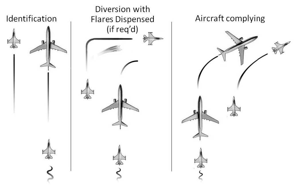
-
Helicopter Intercept phases (see FIG 5-6-2).
- Approach Phase. Aircraft intercepted by helicopter may be approached from any direction, although the helicopter should close for identification and signaling from behind. Generally, the helicopter will approach off the left side of the intercepted aircraft. Safe separation between the helicopter and the unidentified aircraft will be maintained at all times.
- Identification Phase. The helicopter will initiate a controlled closure toward the aircraft of interest, holding at a distance no closer than deemed necessary to establish positive identification and gather the necessary information. The intercepted pilot should expect the interceptor helicopter to take a position off his left wing slightly forward of abeam.
-
Post Intercept Phase. Visual signaling devices may be used in an attempt to communicate with the intercepted aircraft. Visual signaling devices may include, but are not limited to, LED scrolling signboards or blue flashing lights. If compliance is not attained through the use of radios or signaling devices, standard ICAO intercept signals (TBL 5-6-1) may be employed. In order to maintain safe aircraft separation, it is incumbent upon the pilot of the intercepted aircraft not to fall into a trail position (directly behind the helicopter) if instructed to follow the helicopter. This is because the helicopter pilot may lose visual contact with the intercepted aircraft.
NOTE-
Intercepted aircraft must not follow directly behind the helicopter thereby allowing the helicopter pilot to maintain visual contact with the intercepted aircraft and ensuring safe separation is maintained.
FIG 5-6-2
Helicopter Intercept Procedures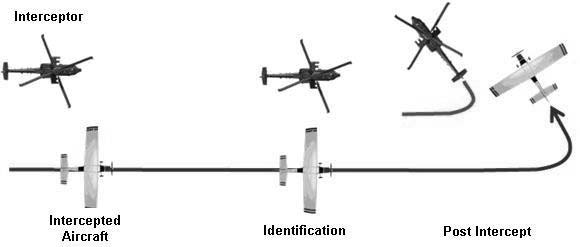
-
Summary of Intercepted Aircraft Actions. An intercepted aircraft must, without delay:
- Adhere to instructions relayed through the use of visual devices, visual signals, and radio communications from the intercepting aircraft.
- Attempt to establish radio communications with the intercepting aircraft or with the appropriate air traffic control facility by making a general call on guard frequencies (121.5 or 243.0 MHz), giving the identity, position, and nature of the flight.
-
If transponder equipped, select Mode 3/A Code 7700 unless otherwise instructed by air traffic control.
NOTE-
If instruction received from any agency conflicts with that given by the intercepting aircraft through visual or radio communications, the intercepted aircraft must seek immediate clarification.
- The crew of the intercepted aircraft must continue to comply with interceptor aircraft signals and instructions until positively released.
-
General.
-
Interception Signals
TBL 5-6-1
Intercepting SignalsINTERCEPTING SIGNALS
Signals initiated by intercepting aircraft and responses by intercepted aircraft
(as set forth in ICAO Annex 2‐Appendix 1, 2.1)Series
INTERCEPTING Aircraft Signals
Meaning
INTERCEPTED Aircraft Responds
Meaning
1
DAY-Rocking wings from a position slightly above and ahead of, and normally to the left of, the intercepted aircraft and, after acknowledgement, a slow level turn, normally to the left, on to the desired heading.
NIGHT‐Same and, in addition, flashing navigational lights at irregular intervals.
NOTE 1-Meteorological conditions or terrain may require the intercepting aircraft to take up a position slightly above and ahead of, and to the right of, the intercepted aircraft and to make the subsequent turn to the right.
NOTE 2-If the intercepted aircraft is not able to keep pace with the intercepting aircraft, the latter is expected to fly a series of race-track patterns and to rock its wings each time it passes the intercepted aircraft.You have been intercepted. Follow me.
AEROPLANES:
DAY-Rocking wings and following.
NIGHT-Same and, in addition, flashing
navigational lights at irregular intervals.
HELICOPTERS:
DAY or NIGHT-Rocking aircraft, flashing navigational lights at irregular intervals and following.Understood, will comply.
2
DAY or NIGHT-An abrupt break-away maneuver from the intercepted aircraft consisting of a climbing turn of 90 degrees or more without crossing the line of flight of the intercepted aircraft.
You may
proceed.AEROPLANES:
DAY or NIGHT‐Rocking wings.
HELICOPTERS:
DAY or NIGHT-Rocking aircraft.Understood, will comply.
3
DAY-Circling aerodrome, lowering landing gear and overflying runway in direction of landing or, if the intercepted aircraft is a helicopter, overflying the helicopter landing area.
NIGHT-Same and, in addition, showing steady landing lights.Land at this aerodrome.
AEROPLANES:
DAY-Lowering landing gear, following the intercepting aircraft and, if after overflying the runway landing is considered safe, proceeding to land.
NIGHT-Same and, in addition, showing steady landing lights (if carried).
HELICOPTERS:
DAY or NIGHT‐Following the intercepting aircraft and proceeding to land, showing a steady landing light (if carried).Understood, will comply.
TBL 5-6-2
Intercepting SignalsINTERCEPTING SIGNALS
Signals and Responses During Aircraft Intercept
Signals initiated by intercepted aircraft and responses by intercepting aircraft
(as set forth in ICAO Annex 2‐Appendix 1, 2.2)Series
INTERCEPTED Aircraft Signals
Meaning
INTERCEPTING Aircraft Responds
Meaning
4
DAY or NIGHT-Raising landing gear (if fitted) and flashing landing lights while passing over runway in use or helicopter landing area at a height exceeding 300m (1,000 ft) but not exceeding 600m (2,000 ft) (in the case of a helicopter, at a height exceeding 50m (170 ft) but not exceeding 100m (330 ft) above the aerodrome level, and continuing to circle runway in use or helicopter landing area. If unable to flash landing lights, flash any other lights available.
Aerodrome you have designated is inadequate.
DAY or NIGHT-If it is desired that the intercepted aircraft follow the intercepting aircraft to an alternate aerodrome, the intercepting aircraft raises its landing gear (if fitted) and uses the Series 1 signals prescribed for intercepting aircraft.
If it is decided to release the intercepted aircraft, the intercepting aircraft uses the Series 2 signals prescribed for intercepting aircraft.Understood, follow me.
Understood, you may
proceed.5
DAY or NIGHT-Regular switching on and off of all available lights but in such a manner as to be distinct from flashing lights.
Cannot comply.
DAY or NIGHT‐Use Series 2 signals prescribed for intercepting aircraft.
Understood.
6
DAY or NIGHT-Irregular flashing of all available lights.
In distress.
DAY or NIGHT‐Use Series 2 signals prescribed for intercepting aircraft.
Understood.
-
ADIZ Boundaries and Designated Mountainous Areas (See FIG 5-6-3.)
FIG 5-6-3
Air Defense Identification Zone Boundaries Designated Mountainous Areas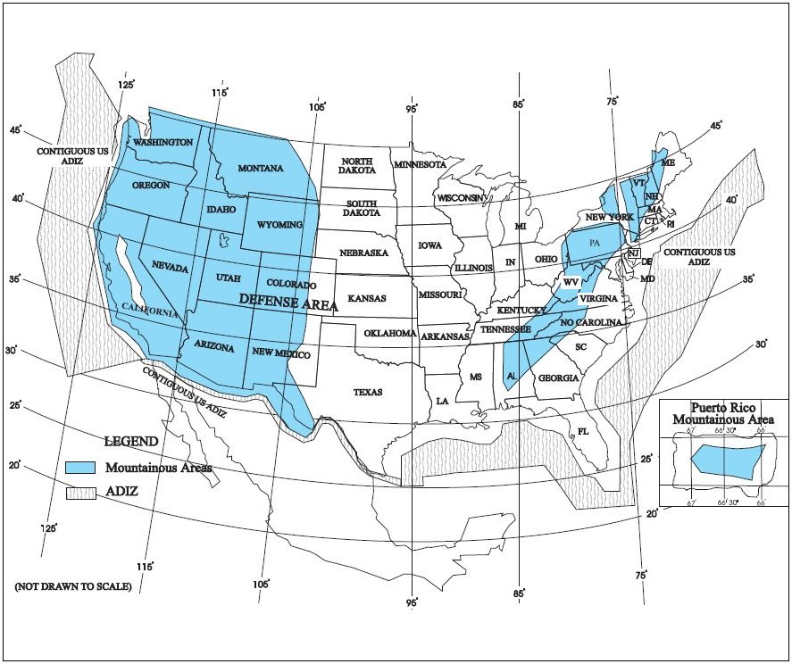
-
Visual Warning System (VWS)
The VWS signal consists of highly-focused red and green colored laser lights designed to illuminate in an alternating red and green signal pattern. These lasers may be directed at specific aircraft suspected of making unauthorized entry into the Washington, DC Special Flight Rules Area (DC SFRA) proceeding on a heading or flight path that may be interpreted as a threat or that operate contrary to the operating rules for the DC SFRA. The beam is neither hazardous to the eyes of pilots/aircrew or passengers, regardless of altitude or distance from the source nor will the beam affect aircraft systems.
- If you are communicating with ATC, and this signal is directed at your aircraft, you are required to contact ATC and advise that you are being illuminated by a visual warning system.
- If this signal is directed at you, and you are not communicating with ATC, you are advised to turn to the most direct heading away from the center of the DC SFRA as soon as possible. Immediately contact ATC on an appropriate frequency, VHF Guard 121.5 or UHF Guard 243.0, and provide your aircraft identification, position, and nature of the flight. Failure to follow these procedures may result in interception by military aircraft. Further noncompliance with interceptor aircraft or ATC may result in the use of force.
-
Pilots planning to operate aircraft in or near the DC SFRA are to familiarize themselves with aircraft intercept procedures. This information applies to all aircraft operating within the DC SFRA including DoD, Law Enforcement, and aircraft engaged in aeromedical operations and does not change procedures established for reporting unauthorized laser illumination as published in FAA Advisory Circulars and Notices.
REFERENCE-
CFR 91.161.
- More details including a video demonstration of the VWS are available from the following FAA website: https://www.faasafety.gov/VisualWarningSystem/VisualWarning.htm.