You have 0 items in your cart

FAR/AIM
>
Aeronautical Information Manual
>
Chapter 5. Air Traffic Procedures
>
Section 3. En Route Procedures
Section 3. En Route Procedures
-
ARTCC Communications
-
Direct Communications, Controllers and Pilots.
- ARTCCs are capable of direct communications with IFR air traffic on certain frequencies. Maximum communications coverage is possible through the use of Remote Center Air/Ground (RCAG) sites comprised of both VHF and UHF transmitters and receivers. These sites are located throughout the U.S. Although they may be several hundred miles away from the ARTCC, they are remoted to the various ARTCCs by land lines or microwave links. Since IFR operations are expedited through the use of direct communications, pilots are requested to use these frequencies strictly for communications pertinent to the control of IFR aircraft. Flight plan filing, en route weather, weather forecasts, and similar data should be requested through FSSs, company radio, or appropriate military facilities capable of performing these services.
- An ARTCC is divided into sectors. Each sector is handled by one or a team of controllers and has its own sector discrete frequency. As a flight progresses from one sector to another, the pilot is requested to change to the appropriate sector discrete frequency.
-
Controller Pilot Data Link Communications (CPDLC) is a system that supplements air/ground voice communications. The CPDLC's principal operating criteria are:
- Voice remains the primary and controlling air/ground communications means.
- Participating aircraft will need to have the appropriate CPDLC avionics equipment in order to receive uplink or transmit downlink messages.
-
En Route CPDLC Initial Services offer the following services: Altimeter Setting (AS), Transfer of Communications (TOC), Initial Contact (IC), and limited route assignments, including airborne reroutes (ABRR), limited altitude assignments, and emergency messages.
-
Altimeter settings will be uplinked automatically when appropriate after a Monitor TOC. Altimeter settings will also be uplinked automatically when an aircraft receives an uplinked altitude assignment below FL 180. A controller may also manually send an altimeter setting message.
NOTE-
When conducting instrument approach procedures, pilots are responsible to obtain and use the appropriate altimeter setting in accordance with 14 CFR section 97.20. CPDLC issued altimeter settings are excluded for this purpose.
- Initial contact is a safety validation transaction that compares a pilot's initiated altitude downlink message with an aircraft's stored altitude in the ATC automation system. When an IC mismatch or Confirm Assigned Altitude (CAA) downlink time-out indicator is displayed in the Full Data Block (FDB) and Aircraft List (ACL), the controller who has track control of the aircraft must use voice communication to verify the assigned altitude of the aircraft, and acknowledge the IC mismatch/time-out indicator.
- Transfer of communications automatically establishes data link contact with a succeeding sector.
- Menu text transmissions are scripted nontrajectory altering uplink messages.
-
The CPDLC Message Elements for the Initial Capabilities rollout are contained in TBL 5-3-1 through TBL 5-3-19, CPDLC Message Elements, below.
NOTE-
The FAA is not implementing ATN B1; the ATN B1 column in the tables is there for informational purposes only
TBL 5-3-1
Route Uplink Message Elements (RTEU)CPDLC Message Sets
Operational Definition in PANS-ATM (Doc 4444)
FANS 1/A
ATN B1
Response
Message Element Identifier
Message Element Intended Use
Format for Message Element Display
UM74 PROCEED DIRECT TO (position)
UM74 PROCEED DIRECT TO (position)
W/U
RTEU-2
Instruction to proceed directly to the specified position.
PROCEED DIRECT TO (position)
UM79 CLEARED TO (position) via (route clearance)
UM79 CLEARED TO (position) via (route clearance)
W/U
RTEU-6
Instruction to proceed to the specified position via the specified route.
CLEARED TO (position) VIA (departure data[O]) (en-route data)
UM80 CLEARED (route clearance)
UM80 CLEARED (route clearance)
W/U
RTEU-7
Instruction to proceed via the specified route.
CLEARED (departure data[O]) (en-route data) (arrival approach data)
UM83 AT (position) CLEARED (route clearance)
N/A
W/U
RTEU-9
Instruction to proceed from the specified position via the specified route.
AT (position) CLEARED (en-route data) (arrival approach data)
TBL 5-3-2
Route Downlink Message Elements (RTED)CPDLC Message Sets
Operational Definition in PANS-ATM (Doc 4444)
FANS 1/A
ATN B1
Response
Message Element Identifier
Message Element Intended Use
Format for Message Element Display
DM22 REQUEST DIRECT TO (position)
DM22 REQUEST DIRECT TO (position)
Y
RTED-1
Request for a direct clearance to the specified position.
REQUEST DIRECT TO (position)
TBL 5-3-3
Lateral Downlink Message Elements (LATD)CPDLC Message Sets
Operational Definition in PANS-ATM (Doc 4444)
FANS 1/A
ATN B1
Response
Message Element Identifier
Message Element Intended Use
Format for Message Element Display
DM59 DIVERTING TO (position) VIA (route clearance)
Note 1. - H alert attribute
Note 2. - N
response attributeN/A
N1
LATD-5
Report indicating diverting to the specified position via the specified route, which may be sent without any previous coordination done with ATC.
DIVERTING TO (position) VIA (en-route data) (arrival approach data[O])
DM60
OFFSETTING (distance offset) (direction) OF ROUTE
Note 1. - H alert attribute
Note 2. - N
response attributeN/A
N1
LATD-6
Report indicating that the aircraft is offsetting to a parallel track at the specified distance in the specified direction off from the cleared route.
OFFSETTING (specified distance) (direction) OF ROUTE
DM80 DEVIATING (deviation offset) (direction) OF ROUTE
Note 1. - H alert attribute
Note 2. - N response attributeN/A
N1
LATD-7
Report indicating deviating specified distance or degrees in the specified direction from the cleared route.
DEVIATING (specifiedDeviation) (direction) OF ROUTE
1 ICAO Document 10037, Global Operational Data Link (GOLD) Manual has these values set to Y in their table.
TBL 5-3-4
Level Uplink Message Elements (LVLU)CPDLC Message Sets
Operational Definition in PANS-ATM (Doc 4444)
FANS 1/A
ATN B1
Response
Message Element Identifier
Message Element Intended Use
Format for Message Element Display
UM19 MAINTAIN (altitude)
Note - Used for a single levelUM19 MAINTAIN (level)
W/U
LVLU-5
Instruction to maintain the specified level or vertical range.
MAINTAIN (level)
UM20 CLIMB TO AND MAINTAIN
(altitude)
Note - Used for a single levelUM20 CLIMB TO (level)
W/U
LVLU-6
Instruction that a climb to the specified level or vertical range is to commence and once reached is to be maintained.
CLIMB TO (level)
UM23 DESCEND TO AND MAINTAIN (altitude)
Note - Used for a single levelUM23 DESCEND TO (level)
W/U
LVLU-9
Instruction that a descent to the specified level or vertical range is to commence and once reached is to be maintained.
DESCEND TO (level)
UM36 EXPEDITE CLIMB TO (altitude)
Note - This message element is equivalent to SUPU-3 plus LVLU-6 in Doc 4444.N/A
W/U
LVLU-6
Instruction that a climb to the specified level or vertical range is to commence and once reached is to be maintained.
CLIMB TO (level)
UM37 EXPEDITE DESCEND TO (altitude)
N/A
W/U
LVLU-9
Instruction that a descent to the specified level or vertical range is to commence and once reached is to be maintained.
DESCEND TO (level)
UM38 IMMEDIATELY CLIMB TO (altitude)
Note - This message element is equivalent to EMGU-2 plus LVLU-6 in Doc 4444.N/A
W/U
LVLU-6
Instruction that a climb to the specified level or vertical range is to commence and once reached is to be maintained.
CLIMB TO (level)
UM39 IMMEDIATELY DESCEND TO (altitude)
Note - This message element is equivalent to EMGU-2 plus LVLU-9 in Doc 4444.N/A
W/U
LVLU-9
Instruction that a descent to the specified level or vertical range is to commence and once reached is to be maintained.
DESCEND TO (level)
UM135 CONFIRM ASSIGNED ALTITUDE
Note - NE response attributeN/A
Y
LVLU-27
Request to confirm the assigned level.
CONFIRM ASSIGNED LEVEL
UM177 AT PILOTS DISCRETION
N/A
NE
See Note
Request to confirm the assigned level.
NOTE-
ICAO Document 10037, Global Operational Data Link (GOLD) Manual does not include this in its tables.
TBL 5-3-5
Level Downlink Message Elements (LVLD)CPDLC Message Sets
Operational Definition in PANS-ATM (Doc 4444)
FANS 1/A
ATN B1
Response
Message Element Identifier
Message Element Intended Use
Format for Message Element Display
DM6 REQUEST (altitude)
Note - Used for a single levelDM6 REQUEST (level)
Y
LVLD-1
Request to fly at the specified level or vertical range.
REQUEST (level)
DM9 REQUEST CLIMB TO (altitude)
DM9 REQUEST CLIMB TO (level)
Y
LVLD-2
Request for a climb to the specified level or vertical range.
REQUEST CLIMB TO (level)
DM10 REQUEST DESCENT TO (altitude)
DM10 REQUEST DESCENT TO (level)
Y
LVLD-3
Request for a descent to the specified level or vertical range.
REQUEST DESCENT TO (level)
DM38 ASSIGNED LEVEL (altitude)
Note - Used for a single levelDM38 ASSIGNED LEVEL (level)
N
LVLD-11
Confirmation that the assigned level or vertical range is the specified level or vertical range.
ASSIGNED LEVEL (level)
DM61 DESCENDING TO (altitude)
Note - urgent alert attributeN/A
N
LVLD-14
Report indicating descending to the specified level.
DESCENDING TO (level single)
TBL 5-3-6
Crossing Constraint Message Elements (CSTU)CPDLC Message Sets
Operational Definition in PANS-ATM (Doc 4444)
FANS 1/A
ATN B1
Response
Message Element Identifier
Message Element Intended Use
Format for Message Element Display
UM49 CROSS (position) AT AND MAINTAIN (altitude)
Note 1. - A vertical range cannot be provided.
Note 2. - This message element is equivalent to CSTU-1 plus LVLU-5 in Doc 4444.N/A
W/U
CSTU-1
Instruction that the specified position is to be crossed at the specified level or within the specified vertical range.
CROSS (position) AT (level)
UM61 CROSS (position) AT AND MAINTAIN (altitude) AT (speed)
Note 1. - A vertical range cannot be provided.
Note 2. - This message element is equivalent to CSTU-14 plus LVLU-5 in Doc 4444.UM61 CROSS (position) AT AND MAINTAIN (level) AT (speed)
W/U
CSTU-14
Instruction that the specified position is to be crossed at the level or within the vertical range, as specified, and at the specified speed.
CROSS (position) AT (level) AT (speed)
TBL 5-3-7
Air Traffic Advisory Uplink Message ElementsCPDLC Message Sets
Operational Definition in PANS-ATM (Doc 4444)
FANS 1/A
ATN B1
Response
Message Element Identifier
Message Element Intended Use
Format for Message Element Display
UM154 RADAR SERVICES TERMINATED
N/A
R
ADVU-2
Advisory that the ATS surveillance service is terminated.
SURVEILLANCE SERVICE TERMINATED
TBL 5-3-8
Voice Communications Uplink Message Elements (COMU)CPDLC Message Sets
Operational Definition in PANS-ATM (Doc 4444)
FANS 1/A
ATN B1
Response
Message Element Identifier
Message Element Intended Use
Format for Message Element Display
UM117 CONTACT (ICAO unit name) (frequency)
UM117 CONTACT (unit name) (frequency)
W/U
COMU-1
Instruction to establish voice contact with the specified ATS unit on the specified frequency.
CONTACT (unit name) (frequency)
UM120 MONITOR (ICAO unit name) (frequency)
UM120 MONITOR (unit name) (frequency)
W/U
COMU-5
Instruction to monitor the specified ATS unit on the specified frequency. The flight crew is not required to establish voice contact on the frequency.
MONITOR (unit name) (frequency)
TBL 5-3-9
Voice Communications Downlink Message Elements (COMD)CPDLC Message Sets
Operational Definition in PANS-ATM (Doc 4444)
FANS 1/A
ATN B1
Response
Message Element Identifier
Message Element Intended Use
Format for Message Element Display
DM20 REQUEST VOICE CONTACT
Note - Used when a frequency is not required.N/A
Y
COMD-1
Request for voice contact on the specified frequency.
REQUEST VOICE CONTACT (frequency)
TBL 5-3-10
Emergency/Urgency Uplink Message Elements (EMGU)CPDLC Message Sets
Operational Definition in PANS-ATM (Doc 4444)
FANS 1/A
ATN B1
Response
Message Element Identifier
Message Element Intended Use
Format for Message Element Display
Used in combination with LVLU-6 and LVLU-9, which is implemented in
FANS 1/A as:
UM38 IMMEDIATELY CLIMB TO (altitude)
UM39 IMMEDIATELY DESCEND TO (altitude)N/A
N
EMGU-2
Instruction to immediately comply with the associated instruction to avoid imminent situation.
Immediately
TBL 5-3-11
Emergency/Urgency Downlink Message Elements (EMGD)CPDLC Message Sets
Operational Definition in PANS-ATM (Doc 4444)
FANS 1/A
ATN B1
Response
Message Element Identifier
Message Element Intended Use
Format for Message Element Display
DM55 PAN PAN PAN Note - N response attribute
N/A
Y
EMGD-1
Indication of an urgent situation.
PAN PAN PAN
DM56 MAYDAY MAYDAY MAYDAY
Note - N response attributeN/A
Y
EMGD-2
Indication of an emergency situation.
MAYDAY
MAYDAY
MAYDAYDM57 (remaining fuel) OF FUEL REMAINING AND (remaining souls) SOULS ON BOARD
Note - N response attributeN/A
Y
EMGD-3
Report indicating fuel remaining (time) and number of persons on board.
(remaining fuel) ENDURANCE AND (persons on board) PERSONS ON BOARD
DM58 CANCEL EMERGENCY
Note - N response attributeN/A
Y
EMGD-4
Indication that the emergency situation is canceled.
CANCEL EMERGENCY
TBL 5-3-12
Standard Response Uplink Message Elements (RSPU)CPDLC Message Sets
Operational Definition in PANS-ATM (Doc 4444)
FANS 1/A
ATN B1
Response
Message Element Identifier
Message Element Intended Use
Format for Message Element Display
UM0 UNABLE
UM0 UNABLE
N
RSPU-1
Indication that the message cannot be complied with.
UNABLE
UM1 STANDBY
UM1 STANDBY
N
RSPU-2
Indication that the message will be responded to shortly.
STANDBY
UM3 ROGER
UM3 ROGER
N
RSPU-4
Indication that the message is received.
ROGER
TBL 5-3-13
Standard Response Downlink Message Elements (RSPD)CPDLC Message Sets
Operational Definition in PANS-ATM (Doc 4444)
FANS 1/A
ATN B1
Response
Message Element Identifier
Message Element Intended Use
Format for Message Element Display
DM0 WILCO
DM0 WILCO
N
RSPD-1
Indication that the instruction is understood and will be complied with.
WILCO
DM1 UNABLE
DM1 UNABLE
N
RSPD-2
Indication that the message cannot be complied with.
UNABLE
DM2 STANDBY
DM2 STANDBY
N
RSPD-3
Indication that the message will be responded to shortly.
STANDBY
DM3 ROGER
Note - ROGER is the only correct response to an uplink free text message.DM3 ROGER
N
RSPD-4
Indication that the message is received.
ROGER
TBL 5-3-14
Supplemental Uplink Message Elements (SUPU)CPDLC Message Sets
Operational Definition in PANS-ATM (Doc 4444)
FANS 1/A
ATN B1
Response
Message Element Identifier
Message Element Intended Use
Format for Message Element Display
UM166 DUE TO TRAFFIC
N/A
N
SUPU-2
Indication that the associated message is issued due to the specified reason.
DUE TO (specified reason uplink)
UM167 DUE TO AIRSPACE RESTRICTION
TBL 5-3-15
Supplemental Downlink Message Elements (SUPD)CPDLC Message Sets
Operational Definition in PANS-ATM (Doc 4444)
FANS 1/A
ATN B1
Response
Message Element Identifier
Message Element Intended Use
Format for Message Element Display
DM65 DUE TO WEATHER
DM65 DUE TO WEATHER
N
SUPD-1
Indication that the associated message is issued due to the specified reason.
DUE TO (specified reason downlink)
DM66 DUE TO AIRCRAFT PERFORMANCE
DM66 DUE TO AIRCRAFT PERFORMANCE
TBL 5-3-16
Free Text Uplink Message Elements (TXTU)CPDLC Message Sets
Operational Definition in PANS-ATM (Doc 4444)
FANS 1/A
ATN B1
Response
Message Element Identifier
Message Element Intended Use
Format for Message Element Display
UM169 (free text)
UM203 (free text)
R
TXTU-1
(free text)
Note-M alert attribute.
UM169 (free text) CPDLC NOT IN USE UNTIL FURTHER NOTIFICATION
N/A
R
See Note
(free text)
UM169 (free text)
“[facility designation]”
LOCAL ALTIMETER (for Altimeter Reporting Station)N/A
R
See Note
(free text)
UM169 (free text)
“[facility designation] LOCAL ALTIMETER MORE THAN ONE HOUR” OLDN/A
R
See Note
(free text)
UM169 (free text)
DUE TO WEATHERN/A
R
See Note
(free text)
UM169 (free text)
REST OF ROUTE UNCHANGEDN/A
R
See Note
(free text)
UM169 (free text)
TRAFFIC FLOW MANAGEMENT REROUTEN/A
R
See Note
(free text)
NOTE-
These are FAA scripted free text messages with no GOLD equivalent.
TBL 5-3-17
Free Text Downlink Message Elements (TXTD)CPDLC Message Sets
Operational Definition in PANS-ATM (Doc 4444)
FANS 1/A
ATN B1
Response
Message Element Identifier
Message Element Intended Use
Format for Message Element Display
DM68 (free text)
Note 1. - Urgency or Distress Alr (M)
Note 2. - Selecting any of the emergency message elements will result in this message element being enabled for the flight crew to include in the emergency message at their discretion.N/A
Y
TXTD-1
(free text)
Note - M alert attribute.TBL 5-3-18
System Management Uplink Message Elements (SYSU)CPDLC Message Sets
Operational Definition in PANS-ATM (Doc 4444)
FANS 1/A
ATN B1
Response
Message Element Identifier
Message Element Intended Use
Format for Message Element Display
UM159 ERROR (error information)
UM159 ERROR (error information)
N
SYSU-1
System-generated notification of an error.
ERROR (error information)
UM160 NEXT DATA AUTHORITY (ICAO facility designation)
Note - The facility designation is required.UM160 NEXT DATA AUTHORITY (facility)
Note - Facility parameter can specify a facility designation or no facility.N
SYSU-2
System-generated notification of the next data authority or the cancellation thereof.
NEXT DATA AUTHORITY (facility designation [O])
TBL 5-3-19
System Management Downlink Message Elements (SYSD)CPDLC Message Sets
Operational Definition in PANS-ATM (Doc 4444)
FANS 1/A
ATN B1
Response
Message Element Identifier
Message Element Intended Use
Format for Message Element Display
DM62 ERROR (error information)
DM62 ERROR (error information)
N
SYSD-1
System-generated notification of an error.
SYSD-1
DM63 NOT CURRENT DATA AUTHORITY
DM63 NOT CURRENT DATA AUTHORITY
N
SYSD-3
System-generated rejection of any CPDLC message sent from a ground facility that is not the current data authority.
SYSD-3
DM64 (ICAO facility designation)
Note - Use by FANS 1/A aircraft in B1 environments.DM107 NOT AUTHORIZED NEXT DATA AUTHORITY
Note - CDA and NDA cannot be provided.N
SYSD-5
System-generated notification that the ground system is not designated as the next data authority (NDA), indicating the identity of the current data authority (CDA). Identity of the NDA, if any, is also reported.
SYSD-5
-
Altimeter settings will be uplinked automatically when appropriate after a Monitor TOC. Altimeter settings will also be uplinked automatically when an aircraft receives an uplinked altitude assignment below FL 180. A controller may also manually send an altimeter setting message.
-
ATC Frequency Change Procedures.
-
The following phraseology will be used by controllers to effect a frequency change:
EXAMPLE-
(Aircraft identification) contact (facility name or location name and terminal function) (frequency) at (time, fix, or altitude).
NOTE-
Pilots are expected to maintain a listening watch on the transferring controller's frequency until the time, fix, or altitude specified. ATC will omit frequency change restrictions whenever pilot compliance is expected upon receipt.
-
The following phraseology should be utilized by pilots for establishing contact with the designated facility:
-
When operating in a radar environment: On initial contact, the pilot should inform the controller of the aircraft's assigned altitude preceded by the words “level,” or “climbing to,” or “descending to,” as appropriate; and the aircraft's present vacating altitude, if applicable.
EXAMPLE-
- (Name) CENTER, (aircraft identification), LEVEL (altitude or flight level).
- (Name) CENTER, (aircraft identification), LEAVING (exact altitude or flight level), CLIMBING TO OR DESCENDING TO (altitude of flight level).
NOTE-
Exact altitude or flight level means to the nearest 100 foot increment. Exact altitude or flight level reports on initial contact provide ATC with information required prior to using Mode C altitude information for separation purposes.
-
When operating in a nonradar environment:
-
On initial contact, the pilot should inform the controller of the aircraft's present position, altitude and time estimate for the next reporting point.
EXAMPLE-
(Name) CENTER, (aircraft identification), (position), (altitude), ESTIMATING (reporting point) AT (time).
-
After initial contact, when a position report will be made, the pilot should give the controller a complete position report.
EXAMPLE-
(Name) CENTER, (aircraft identification), (position), (time), (altitude), (type of flight plan), (ETA and name of next reporting point), (the name of the next succeeding reporting point), AND (remarks).
REFERENCE-
AIM, Para 5-3-2, Position Reporting.
-
On initial contact, the pilot should inform the controller of the aircraft's present position, altitude and time estimate for the next reporting point.
-
When operating in a radar environment: On initial contact, the pilot should inform the controller of the aircraft's assigned altitude preceded by the words “level,” or “climbing to,” or “descending to,” as appropriate; and the aircraft's present vacating altitude, if applicable.
-
At times controllers will ask pilots to verify that they are at a particular altitude. The phraseology used will be: “VERIFY AT (altitude).” In climbing or descending situations, controllers may ask pilots to “VERIFY ASSIGNED ALTITUDE AS (altitude).” Pilots should confirm that they are at the altitude stated by the controller or that the assigned altitude is correct as stated. If this is not the case, they should inform the controller of the actual altitude being maintained or the different assigned altitude.
CAUTION-
Pilots should not take action to change their actual altitude or different assigned altitude to the altitude stated in the controllers verification request unless the controller specifically authorizes a change.
-
The following phraseology will be used by controllers to effect a frequency change:
-
ARTCC Radio Frequency Outage. ARTCCs normally have at least one back‐up radio receiver and transmitter system for each frequency, which can usually be placed into service quickly with little or no disruption of ATC service. Occasionally, technical problems may cause a delay but switchover seldom takes more than 60 seconds. When it appears that the outage will not be quickly remedied, the ARTCC will usually request a nearby aircraft, if there is one, to switch to the affected frequency to broadcast communications instructions. It is important, therefore, that the pilot wait at least 1 minute before deciding that the ARTCC has actually experienced a radio frequency failure. When such an outage does occur, the pilot should, if workload and equipment capability permit, maintain a listening watch on the affected frequency while attempting to comply with the following recommended communications procedures:
- If two‐way communications cannot be established with the ARTCC after changing frequencies, a pilot should attempt to recontact the transferring controller for the assignment of an alternative frequency or other instructions.
-
When an ARTCC radio frequency failure occurs after two‐way communications have been established, the pilot should attempt to reestablish contact with the center on any other known ARTCC frequency, preferably that of the next responsible sector when practicable, and ask for instructions. However, when the next normal frequency change along the route is known to involve another ATC facility, the pilot should contact that facility, if feasible, for instructions. If communications cannot be reestablished by either method, the pilot is expected to request communications instructions from the FSS appropriate to the route of flight.
NOTE-
The exchange of information between an aircraft and an ARTCC through an FSS is quicker than relay via company radio because the FSS has direct interphone lines to the responsible ARTCC sector. Accordingly, when circumstances dictate a choice between the two, during an ARTCC frequency outage, relay via FSS radio is recommended.
- Oakland Oceanic FIR. The use of CPDLC and ADS-C in the Oakland Oceanic FIR (KZAK) is only permitted by Inmarsat and Iridium customers. All other forms of data link connectivity are not authorized. Users must ensure that the proper data link code is filed in Item 10a of the ICAO FPL in order to indicate which satellite medium(s) the aircraft is equipped with. The identifier for Inmarsat is J5 and the identifier for Iridium is J7. If J5 or J7 is not included in the ICAO FPL, then the LOGON will be rejected by KZAK and the aircraft will not be able to connect.
- New York Oceanic FIR. The use of CPDLC and ADS-C in the New York Oceanic FIR (KZWY) is only permitted by Inmarsat and Iridium customers. All other forms of data link connectivity are not authorized. Users must ensure that the proper data link code is filed in Item 10a of the ICAO FPL in order to indicate which satellite medium(s) the aircraft is equipped with. The identifier for Inmarsat is J5 and the identifier for Iridium is J7. If J5 or J7 is not included in the ICAO FPL, then the LOGON will be rejected by KZWY and the aircraft will not be able to connect.
-
Direct Communications, Controllers and Pilots.
-
Position Reporting
The safety and effectiveness of traffic control depends to a large extent on accurate position reporting. In order to provide the proper separation and expedite aircraft movements, ATC must be able to make accurate estimates of the progress of every aircraft operating on an IFR flight plan.
-
Position Identification.
- When a position report is to be made passing a VOR radio facility, the time reported should be the time at which the first complete reversal of the “to/from” indicator is accomplished.
- When a position report is made passing a facility by means of an airborne ADF, the time reported should be the time at which the indicator makes a complete reversal.
- When an aural or a light panel indication is used to determine the time passing a reporting point, such as a fan marker, Z marker, cone of silence or intersection of range courses, the time should be noted when the signal is first received and again when it ceases. The mean of these two times should then be taken as the actual time over the fix.
- If a position is given with respect to distance and direction from a reporting point, the distance and direction should be computed as accurately as possible.
- Except for terminal area transition purposes, position reports or navigation with reference to aids not established for use in the structure in which flight is being conducted will not normally be required by ATC.
-
Position Reporting Points. CFRs require pilots to maintain a listening watch on the appropriate frequency and, unless operating under the provisions of subparagraph c, to furnish position reports passing certain reporting points. Reporting points are indicated by symbols on en route charts. The designated compulsory reporting point symbol is a solid triangle
 and the “on request” reporting point symbol is the open triangle
  . Reports passing an “on request” reporting point are only necessary when requested by ATC.
-
Position Reporting Requirements.
- Flights Along Airways or Routes. A position report is required by all flights regardless of altitude, including those operating in accordance with an ATC clearance specifying “VFR-on-top,” over each designated compulsory reporting point along the route being flown.
- Flights Along a Direct Route. Regardless of the altitude or flight level being flown, including flights operating in accordance with an ATC clearance specifying “VFR-on-top,” pilots must report over each reporting point used in the flight plan to define the route of flight.
- Flights in a Radar Environment. When informed by ATC that their aircraft are in “Radar Contact,” pilots should discontinue position reports over designated reporting points. They should resume normal position reporting when ATC advises “RADAR CONTACT LOST” or “RADAR SERVICE TERMINATED.”
-
Flights in an Oceanic (Nonradar) Environment. Pilots must report over each point used in the flight plan to define the route of flight, even if the point is depicted on aeronautical charts as an “on request" (non-compulsory) reporting point. For aircraft providing automatic position reporting via an Automatic Dependent Surveillance-Contract (ADS-C) logon, pilots should discontinue voice position reports.
NOTE-
ATC will inform pilots that they are in “radar contact”:
- when their aircraft is initially identified in the ATC system; and
- when radar identification is reestablished after radar service has been terminated or radar contact lost.
Subsequent to being advised that the controller has established radar contact, this fact will not be repeated to the pilot when handed off to another controller. At times, the aircraft identity will be confirmed by the receiving controller; however, this should not be construed to mean that radar contact has been lost. The identity of transponder equipped aircraft will be confirmed by asking the pilot to “ident,” “squawk standby,” or to change codes. Aircraft without transponders will be advised of their position to confirm identity. In this case, the pilot is expected to advise the controller if in disagreement with the position given. Any pilot who cannot confirm the accuracy of the position given because of not being tuned to the NAVAID referenced by the controller, should ask for another radar position relative to the tuned in NAVAID.
-
Position Report Items:
-
Position reports should include the following items:
- Identification;
- Position;
- Time;
- Altitude or flight level (include actual altitude or flight level when operating on a clearance specifying VFR-on-top);
- Type of flight plan (not required in IFR position reports made directly to ARTCCs or approach control);
- ETA and name of next reporting point;
- The name only of the next succeeding reporting point along the route of flight; and
- Pertinent remarks.
-
Position reports should include the following items:
-
Position Identification.
-
Additional Reports
-
The following reports should be made to ATC or FSS facilities without a specific ATC request:
-
At all times.
- When vacating any previously assigned altitude or flight level for a newly assigned altitude or flight level.
- When an altitude change will be made if operating on a clearance specifying VFR-on-top.
- When unable to climb/descend at a rate of a least 500 feet per minute.
- When approach has been missed. (Request clearance for specific action; i.e., to alternative airport, another approach, etc.)
- Change in the average true airspeed (at cruising altitude) when it varies by 5 percent or 10 knots (whichever is greater) from that filed in the flight plan.
- The time and altitude or flight level upon reaching a holding fix or point to which cleared.
-
When leaving any assigned holding fix or point.
NOTE-
The reports in subparagraphs (f) and (g) may be omitted by pilots of aircraft involved in instrument training at military terminal area facilities when radar service is being provided.
-
Any loss, in controlled airspace, of VOR, TACAN, ADF, low frequency navigation receiver capability, GPS anomalies while using installed IFR-certified GPS/GNSS receivers, complete or partial loss of ILS receiver capability or impairment of air/ground communications capability. Reports should include aircraft identification, equipment affected, degree to which the capability to operate under IFR in the ATC system is impaired, and the nature and extent of assistance desired from ATC.
NOTE-
- Other equipment installed in an aircraft may effectively impair safety and/or the ability to operate under IFR. If such equipment (e.g., airborne weather radar) malfunctions and in the pilot's judgment either safety or IFR capabilities are affected, reports should be made as above.
- When reporting GPS anomalies, include the location and altitude of the anomaly. Be specific when describing the location and include duration of the anomaly if necessary.
- Any information relating to the safety of flight.
-
When not in radar contact.
- When leaving final approach fix inbound on final approach (nonprecision approach) or when leaving the outer marker or fix used in lieu of the outer marker inbound on final approach (precision approach).
- A corrected estimate at anytime it becomes apparent that an estimate as previously submitted is in error in excess of 2 minutes. For flights in the North Atlantic (NAT), a revised estimate is required if the error is 3 minutes or more.
-
At all times.
-
Pilots encountering weather conditions which have not been forecast, or hazardous conditions which have been forecast, are expected to forward a report of such weather to ATC.
REFERENCE-
AIM, Para 7-1-18, Pilot Weather Reports (PIREPs).
14 CFR Section 91.183(B) and (C).
-
The following reports should be made to ATC or FSS facilities without a specific ATC request:
-
Airways and Route Systems
-
Three fixed route systems are established for air navigation purposes. They are the Federal airway system (consisting of VOR and L/MF routes), the jet route system, and the RNAV route system. To the extent possible, these route systems are aligned in an overlying manner to facilitate transition between each.
-
The VOR and L/MF (nondirectional radio beacons) Airway System consists of airways designated from 1,200 feet above the surface (or in some instances higher) up to but not including 18,000 feet MSL. These airways are depicted on IFR Enroute Low Altitude Charts.
NOTE-
The altitude limits of a victor airway should not be exceeded except to effect transition within or between route structures.
-
Except in Alaska, the VOR airways are: predicated solely on VOR or VORTAC navigation aids; depicted in black on aeronautical charts; and identified by a “V” (Victor) followed by the airway number (for example, V12).
NOTE-
Segments of VOR airways in Alaska are based on L/MF navigation aids and charted in brown instead of black on en route charts.
-
A segment of an airway which is common to two or more routes carries the numbers of all the airways which coincide for that segment. When such is the case, pilots filing a flight plan need to indicate only that airway number for the route filed.
NOTE-
A pilot who intends to make an airway flight, using VOR facilities, will simply specify the appropriate “victor” airway(s) in the flight plan. For example, if a flight is to be made from Chicago to New Orleans at 8,000 feet, using omniranges only, the route may be indicated as “departing from Chicago-Midway, cruising 8,000 feet via Victor 9 to Moisant International.” If flight is to be conducted in part by means of L/MF navigation aids and in part on omniranges, specifications of the appropriate airways in the flight plan will indicate which types of facilities will be used along the described routes, and, for IFR flight, permit ATC to issue a traffic clearance accordingly. A route may also be described by specifying the station over which the flight will pass, but in this case since many VORs and L/MF aids have the same name, the pilot must be careful to indicate which aid will be used at a particular location. This will be indicated in the route of flight portion of the flight plan by specifying the type of facility to be used after the location name in the following manner: Newark L/MF, Allentown VOR.
- With respect to position reporting, reporting points are designated for VOR Airway Systems. Flights using Victor Airways will report over these points unless advised otherwise by ATC.
-
A segment of an airway which is common to two or more routes carries the numbers of all the airways which coincide for that segment. When such is the case, pilots filing a flight plan need to indicate only that airway number for the route filed.
- The L/MF airways (colored airways) are predicated solely on L/MF navigation aids and are depicted in brown on aeronautical charts and are identified by color name and number (e.g., Amber One). Green and Red airways are plotted east and west. Amber and Blue airways are plotted north and south.
- The use of TSO-C145 (as revised) or TSO-C146 (as revised) GPS/WAAS navigation systems is allowed in Alaska as the only means of navigation on published air traffic service (ATS) routes, including those Victor, T-Routes, and colored airway segments designated with a second minimum en route altitude (MEA) depicted in blue and followed by the letter G at those lower altitudes. The altitudes so depicted are below the minimum reception altitude (MRA) of the land-based navigation facility defining the route segment, and guarantee standard en route obstacle clearance and two-way communications. Air carrier operators requiring operations specifications are authorized to conduct operations on those routes in accordance with FAA operations specifications.
-
Except in Alaska, the VOR airways are: predicated solely on VOR or VORTAC navigation aids; depicted in black on aeronautical charts; and identified by a “V” (Victor) followed by the airway number (for example, V12).
-
The jet route system consists of jet routes established from 18,000 feet MSL to FL 450 inclusive.
-
These routes are depicted on Enroute High Altitude Charts. Jet routes are depicted in black on aeronautical charts and are identified by a “J” (Jet) followed by the airway number (e.g., J12). Jet routes, as VOR airways, are predicated solely on VOR or VORTAC navigation facilities (except in Alaska).
NOTE-
Segments of jet routes in Alaska are based on L/MF navigation aids and are charted in brown color instead of black on en route charts.
- With respect to position reporting, reporting points are designated for jet route systems. Flights using jet routes will report over these points unless otherwise advised by ATC.
-
These routes are depicted on Enroute High Altitude Charts. Jet routes are depicted in black on aeronautical charts and are identified by a “J” (Jet) followed by the airway number (e.g., J12). Jet routes, as VOR airways, are predicated solely on VOR or VORTAC navigation facilities (except in Alaska).
-
Area Navigation (RNAV) Routes.
-
Published RNAV routes, including Q-routes, T-routes, and Y-routes, can be flight planned for use by aircraft with RNAV capability, subject to any limitations or requirements noted on en route charts, in applicable Advisory Circulars, NOTAMs, etc. RNAV routes are normally depicted in blue on aeronautical charts and are identified by the letter “Q,” “T,” or “Y” followed by the airway number (for example, Q13, T205, and Y280). Published RNAV routes are RNAV 2 except when specifically charted as RNAV 1. Unless otherwise specified, these routes require system performance currently met by GPS, GPS/WAAS, or DME/DME/IRU RNAV systems that satisfy the criteria discussed in AC 90-100A, U.S. Terminal and En Route Area Navigation (RNAV) Operations.
-
Q-routes are available for use by RNAV equipped aircraft between 18,000 feet MSL and FL 450 inclusive. Q-routes are depicted on Enroute High Altitude Charts.
NOTE-
Aircraft in Alaska may only operate on GNSS Q-routes with GPS (TSO-C129 (as revised) or TSO-C196 (as revised)) equipment while the aircraft remains in Air Traffic Control (ATC) radar surveillance or with GPS/WAAS which does not require ATC radar surveillance.
-
T-routes are available for use by GPS or GPS/WAAS equipped aircraft from 1,200 feet above the surface (or in some instances higher) up to but not including 18,000 feet MSL. T-routes are depicted on Enroute Low Altitude Charts.
NOTE-
Aircraft in Alaska may only operate on GNSS T-routes with GPS/WAAS (TSO-C145 (as revised) or TSO-C146 (as revised)) equipment.
- Y-routes generally run in U.S. offshore airspace, however operators can find some Y-routes over southern Florida. Pilots must use GPS for navigation and meet RNAV 2 performance requirements for all flights on Y-routes. Operators can find additional Y-route requirements in the U.S. Aeronautical Information Publication (AIP), ENR 7.10, available on the FAA website.
-
Q-routes are available for use by RNAV equipped aircraft between 18,000 feet MSL and FL 450 inclusive. Q-routes are depicted on Enroute High Altitude Charts.
- Unpublished RNAV routes are direct routes, based on area navigation capability, between waypoints defined in terms of latitude/longitude coordinates, degree-distance fixes, or offsets from established routes/airways at a specified distance and direction. Radar monitoring by ATC is required on all unpublished RNAV routes, except for GNSS-equipped aircraft cleared via filed published waypoints recallable from the aircraft's navigation database.
- Magnetic Reference Bearing (MRB) is the published bearing between two waypoints on an RNAV/GPS/GNSS route. The MRB is calculated by applying magnetic variation at the waypoint to the calculated true course between two waypoints. The MRB enhances situational awareness by indicating a reference bearing (no-wind heading) that a pilot should see on the compass/HSI/RMI, etc., when turning prior to/over a waypoint en route to another waypoint. Pilots should use this bearing as a reference only, because their RNAV/GPS/GNSS navigation system will fly the true course between the waypoints.
-
Published RNAV routes, including Q-routes, T-routes, and Y-routes, can be flight planned for use by aircraft with RNAV capability, subject to any limitations or requirements noted on en route charts, in applicable Advisory Circulars, NOTAMs, etc. RNAV routes are normally depicted in blue on aeronautical charts and are identified by the letter “Q,” “T,” or “Y” followed by the airway number (for example, Q13, T205, and Y280). Published RNAV routes are RNAV 2 except when specifically charted as RNAV 1. Unless otherwise specified, these routes require system performance currently met by GPS, GPS/WAAS, or DME/DME/IRU RNAV systems that satisfy the criteria discussed in AC 90-100A, U.S. Terminal and En Route Area Navigation (RNAV) Operations.
-
The VOR and L/MF (nondirectional radio beacons) Airway System consists of airways designated from 1,200 feet above the surface (or in some instances higher) up to but not including 18,000 feet MSL. These airways are depicted on IFR Enroute Low Altitude Charts.
- Operation above FL 450 may be conducted on a point‐to‐point basis. Navigational guidance is provided on an area basis utilizing those facilities depicted on the enroute high altitude charts.
- Radar Vectors. Controllers may vector aircraft within controlled airspace for separation purposes, noise abatement considerations, when an operational advantage will be realized by the pilot or the controller, or when requested by the pilot. Vectors outside of controlled airspace will be provided only on pilot request. Pilots will be advised as to what the vector is to achieve when the vector is controller initiated and will take the aircraft off a previously assigned nonradar route. To the extent possible, aircraft operating on RNAV routes will be allowed to remain on their own navigation.
-
When flying in Canadian airspace, pilots are cautioned to review Canadian Air Regulations.
-
Special attention should be given to the parts which differ from U.S. CFRs.
- The Canadian Airways Class B airspace restriction is an example. Class B airspace is all controlled low level airspace above 12,500 feet MSL or the MEA, whichever is higher, within which only IFR and controlled VFR flights are permitted. (Low level airspace means an airspace designated and defined as such in the Designated Airspace Handbook.)
- Unless issued a VFR flight clearance by ATC, regardless of the weather conditions or the height of the terrain, no person may operate an aircraft under VMC within Class B airspace.
- The requirement for entry into Class B airspace is a student pilot permit (under the guidance or control of a flight instructor).
- VFR flight requires visual contact with the ground or water at all times.
-
Segments of VOR airways and high level routes in Canada are based on L/MF navigation aids and are charted in brown color instead of blue on en route charts.
FIG 5-3-1
Adhering to Airways or Routes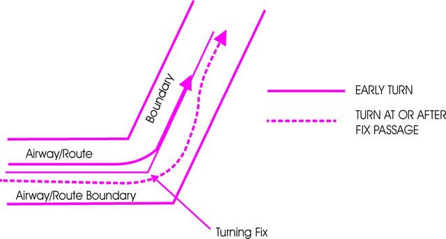
-
Special attention should be given to the parts which differ from U.S. CFRs.
-
Three fixed route systems are established for air navigation purposes. They are the Federal airway system (consisting of VOR and L/MF routes), the jet route system, and the RNAV route system. To the extent possible, these route systems are aligned in an overlying manner to facilitate transition between each.
-
Airway or Route Course Changes
- Pilots of aircraft are required to adhere to airways or routes being flown. Special attention must be given to this requirement during course changes. Each course change consists of variables that make the technique applicable in each case a matter only the pilot can resolve. Some variables which must be considered are turn radius, wind effect, airspeed, degree of turn, and cockpit instrumentation. An early turn, as illustrated below, is one method of adhering to airways or routes. The use of any available cockpit instrumentation, such as Distance Measuring Equipment, may be used by the pilot to lead the turn when making course changes. This is consistent with the intent of 14 CFR section 91.181, which requires pilots to operate along the centerline of an airway and along the direct course between navigational aids or fixes.
- Turns which begin at or after fix passage may exceed airway or route boundaries. FIG 5-3-1 contains an example flight track depicting this, together with an example of an early turn.
- Without such actions as leading a turn, aircraft operating in excess of 290 knots true air speed (TAS) can exceed the normal airway or route boundaries depending on the amount of course change required, wind direction and velocity, the character of the turn fix (DME, overhead navigation aid, or intersection), and the pilot's technique in making a course change. For example, a flight operating at 17,000 feet MSL with a TAS of 400 knots, a 25 degree bank, and a course change of more than 40 degrees would exceed the width of the airway or route; i.e., 4 nautical miles each side of centerline. However, in the airspace below 18,000 feet MSL, operations in excess of 290 knots TAS are not prevalent and the provision of additional IFR separation in all course change situations for the occasional aircraft making a turn in excess of 290 knots TAS creates an unacceptable waste of airspace and imposes a penalty upon the preponderance of traffic which operate at low speeds. Consequently, the FAA expects pilots to lead turns and take other actions they consider necessary during course changes to adhere as closely as possible to the airways or route being flown.
-
Changeover Points (COPs)
- COPs are prescribed for Federal airways, jet routes, area navigation routes, or other direct routes for which an MEA is designated under 14 CFR part 95. The COP is a point along the route or airway segment between two adjacent navigation facilities or waypoints where changeover in navigation guidance should occur. At this point, the pilot should change navigation receiver frequency from the station behind the aircraft to the station ahead.
- The COP is normally located midway between the navigation facilities for straight route segments, or at the intersection of radials or courses forming a dogleg in the case of dogleg route segments. When the COP is NOT located at the midway point, aeronautical charts will depict the COP location and give the mileage to the radio aids.
- COPs are established for the purpose of preventing loss of navigation guidance, to prevent frequency interference from other facilities, and to prevent use of different facilities by different aircraft in the same airspace. Pilots are urged to observe COPs to the fullest extent.
-
Minimum Turning Altitude (MTA)
Due to increased airspeeds at 10,000 ft MSL or above, the published minimum enroute altitude (MEA) may not be sufficient for obstacle clearance when a turn is required over a fix, NAVAID, or waypoint. In these instances, an expanded area in the vicinity of the turn point is examined to determine whether the published MEA is sufficient for obstacle clearance. In some locations (normally mountainous), terrain/obstacles in the expanded search area may necessitate a higher minimum altitude while conducting the turning maneuver. Turning fixes requiring a higher minimum turning altitude (MTA) will be denoted on government charts by the minimum crossing altitude (MCA) icon (“x" flag) and an accompanying note describing the MTA restriction. An MTA restriction will normally consist of the air traffic service (ATS) route leading to the turn point, the ATS route leading from the turn point, and the required altitude; e.g., MTA V330 E TO V520 W 16000. When an MTA is applicable for the intended route of flight, pilots must ensure they are at or above the charted MTA not later than the turn point and maintain at or above the MTA until joining the centerline of the ATS route following the turn point. Once established on the centerline following the turning fix, the MEA/MOCA determines the minimum altitude available for assignment. An MTA may also preclude the use of a specific altitude or a range of altitudes during a turn. For example, the MTA may restrict the use of 10,000 through 11,000 ft MSL. In this case, any altitude greater than 11,000 ft MSL is unrestricted, as are altitudes less than 10,000 ft MSL provided MEA/MOCA requirements are satisfied.
-
Holding
-
Whenever an aircraft is cleared to a fix other than the destination airport and delay is expected, it is the responsibility of ATC to issue complete holding instructions (unless the pattern is charted), an EFC time and best estimate of any additional en route/terminal delay.
NOTE-
Only those holding patterns depicted on U.S. government or commercially produced (meeting FAA requirements) low/high altitude en route, and area or STAR charts should be used.
- If the holding pattern is charted and the controller doesn't issue complete holding instructions, the pilot is expected to hold as depicted on the appropriate chart. When the pattern is charted on the assigned procedure or route being flown, ATC may omit all holding instructions except the charted holding direction and the statement AS PUBLISHED; for example, HOLD EAST AS PUBLISHED. ATC must always issue complete holding instructions when pilots request them.
- If no holding pattern is charted and holding instructions have not been issued, the pilot should ask ATC for holding instructions prior to reaching the fix. This procedure will eliminate the possibility of an aircraft entering a holding pattern other than that desired by ATC. If unable to obtain holding instructions prior to reaching the fix (due to frequency congestion, stuck microphone, etc.), then enter a standard pattern on the course on which the aircraft approached the fix and request further clearance as soon as possible. In this event, the altitude/flight level of the aircraft at the clearance limit will be protected so that separation will be provided as required.
- When an aircraft is 3 minutes or less from a clearance limit and a clearance beyond the fix has not been received, the pilot is expected to start a speed reduction so that the aircraft will cross the fix, initially, at or below the maximum holding airspeed.
- When no delay is expected, the controller should issue a clearance beyond the fix as soon as possible and, whenever possible, at least 5 minutes before the aircraft reaches the clearance limit.
-
Pilots should report to ATC the time and altitude/flight level at which the aircraft reaches the clearance limit and report leaving the clearance limit.
NOTE-
In the event of two‐way communications failure, pilots are required to comply with 14 CFR section 91.185.
- When holding at a VOR station, pilots should begin the turn to the outbound leg at the time of the first complete reversal of the to/from indicator.
-
Patterns at the most generally used holding fixes are depicted (charted) on U.S. Government or commercially produced (meeting FAA requirements) Low or High Altitude En Route, Area, Departure Procedure, and STAR Charts. Pilots are expected to hold in the pattern depicted unless specifically advised otherwise by ATC.
NOTE-
Holding patterns that protect for a maximum holding airspeed other than the standard may be depicted by an icon, unless otherwise depicted. The icon is a standard holding pattern symbol (racetrack) with the airspeed restriction shown in the center. In other cases, the airspeed restriction will be depicted next to the standard holding pattern symbol.
REFERENCE-
-
An ATC clearance requiring an aircraft to hold at a fix where the pattern is not charted will include the following information: (See FIG 5-3-2.)
- Direction of holding from the fix in terms of the eight cardinal compass points (i.e., N, NE, E, SE, etc.).
- Holding fix (the fix may be omitted if included at the beginning of the transmission as the clearance limit).
- Radial, course, bearing, airway or route on which the aircraft is to hold.
- Leg length in miles if DME or RNAV is to be used (leg length will be specified in minutes on pilot request or if the controller considers it necessary).
- Direction of turn if left turns are to be made, the pilot requests, or the controller considers it necessary.
-
Time to expect further clearance and any pertinent additional delay information.
FIG 5-3-2
Holding Patterns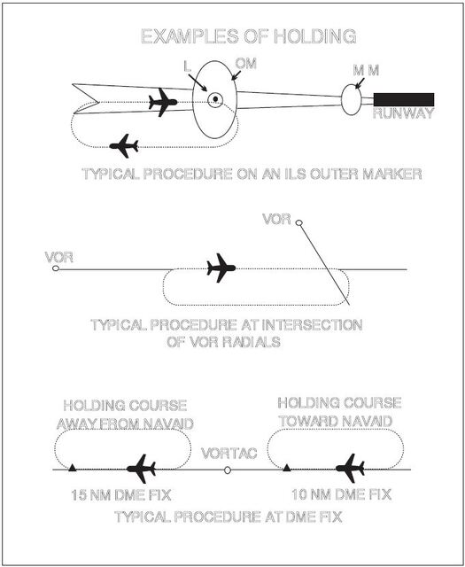
FIG 5-3-3
Holding Pattern Descriptive Terms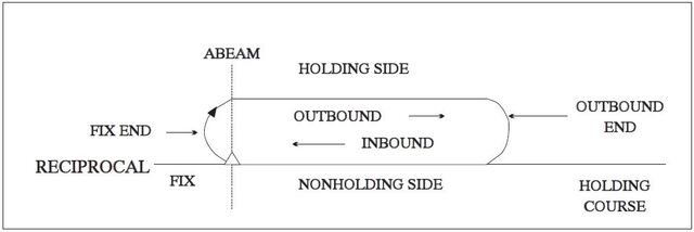
-
Holding pattern airspace protection is based on the following procedures.
-
Descriptive Terms.
- Standard Pattern. Right turns (See FIG 5-3-3.)
- Nonstandard Pattern. Left turns
-
Airspeeds.
-
All aircraft may hold at the following altitudes and maximum holding airspeeds:
TBL 5-3-20
Altitude (MSL)
Airspeed (KIAS)
MHA - 6,000'
200
6,001' - 14,000'
230
14,001' and above
265
NOTE-
These are the maximum indicated air speeds applicable to all holding.
-
The following are exceptions to the maximum holding airspeeds:
- Holding patterns from 6,001' to 14,000' may be restricted to a maximum airspeed of 210 KIAS. This nonstandard pattern will be depicted by an icon.
- Holding patterns may be restricted to a maximum speed. The speed restriction is depicted in parenthesis inside the holding pattern on the chart: e.g., (175). The aircraft should be at or below the maximum speed prior to initially crossing the holding fix to avoid exiting the protected airspace. Pilots unable to comply with the maximum airspeed restriction should notify ATC.
- Holding patterns at USAF airfields only - 310 KIAS maximum, unless otherwise depicted.
- Holding patterns at Navy fields only - 230 KIAS maximum, unless otherwise depicted.
- All helicopter/power lift aircraft holding on a “COPTER” instrument procedure is predicated on a minimum airspeed of 90 KIAS unless charted otherwise.
- When a climb-in hold is specified by a published procedure (for example, “Climb-in holding pattern to depart XYZ VORTAC at or above 10,000.” or “All aircraft climb-in TRUCK holding pattern to cross TRUCK Int at or above 11,500 before proceeding on course.”), additional obstacle protection area has been provided to allow for greater airspeeds in the climb for those aircraft requiring them. A maximum airspeed of 310 KIAS is permitted in Climb-in-holding, unless a maximum holding airspeed is published, in which case that maximum airspeed is applicable. The airspeed limitations in 14 CFR section 91.117, Aircraft Speed, still apply.
-
The following phraseology may be used by an ATCS to advise a pilot of the maximum holding airspeed for a holding pattern airspace area.
PHRASEOLOGY-
(AIRCRAFT IDENTIFICATION) (holding instructions, when needed) MAXIMUM HOLDING AIRSPEED IS (speed in knots).
FIG 5-3-4
Holding Pattern Entry Procedures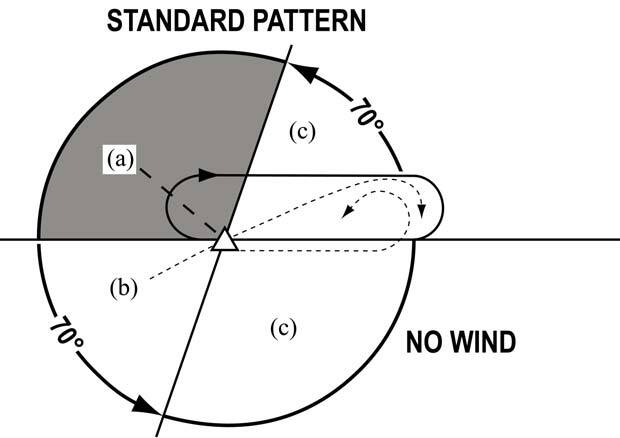
-
All aircraft may hold at the following altitudes and maximum holding airspeeds:
-
Entry Procedures. Holding protected airspace is designed based in part on pilot compliance with the three recommended holding pattern entry procedures discussed below. Deviations from these recommendations, coupled with excessive airspeed crossing the holding fix, may in some cases result in the aircraft exceeding holding protected airspace. (See FIG 5-3-4.)
- Parallel Procedure. When approaching the holding fix from anywhere in sector (a), the parallel entry procedure would be to turn to a heading to parallel the holding course outbound on the nonholding side for one minute, turn in the direction of the holding pattern through more than 180 degrees, and return to the holding fix or intercept the holding course inbound.
- Teardrop Procedure. When approaching the holding fix from anywhere in sector (b), the teardrop entry procedure would be to fly to the fix, turn outbound to a heading for a 30 degree teardrop entry within the pattern (on the holding side) for a period of one minute, then turn in the direction of the holding pattern to intercept the inbound holding course.
- Direct Entry Procedure. When approaching the holding fix from anywhere in sector (c), the direct entry procedure would be to fly directly to the fix and turn to follow the holding pattern.
- While other entry procedures may enable the aircraft to enter the holding pattern and remain within protected airspace, the parallel, teardrop and direct entries are the procedures for entry and holding recommended by the FAA, and were derived as part of the development of the size and shape of the obstacle protection areas for holding.
- Nonstandard Holding Pattern. Fix end and outbound end turns are made to the left. Entry procedures to a nonstandard pattern are oriented in relation to the 70 degree line on the holding side just as in the standard pattern.
-
Timing.
-
Inbound Leg.
- At or below 14,000 feet MSL: 1 minute.
-
Above 14,000 feet MSL: 11/2 minutes.
NOTE-
The initial outbound leg should be flown for 1 minute or 1 1/2 minutes (appropriate to altitude). Timing for subsequent outbound legs should be adjusted, as necessary, to achieve proper inbound leg time. Pilots may use any navigational means available; i.e., DME, RNAV, etc., to ensure the appropriate inbound leg times.
- Outbound leg timing begins over/abeam the fix, whichever occurs later. If the abeam position cannot be determined, start timing when turn to outbound is completed.
-
Inbound Leg.
-
Distance Measuring Equipment (DME)/ GPS Along-Track Distance (ATD). DME/GPS holding is subject to the same entry and holding procedures except that distances (nautical miles) are used in lieu of time values. The outbound course of the DME/GPS holding pattern is called the outbound leg of the pattern. The controller or the instrument approach procedure chart will specify the length of the outbound leg. The end of the outbound leg is determined by the DME or ATD readout. The holding fix on conventional procedures, or controller defined holding based on a conventional navigation aid with DME, is a specified course or radial and distances are from the DME station for both the inbound and outbound ends of the holding pattern. When flying published GPS overlay or stand alone procedures with distance specified, the holding fix will be a waypoint in the database and the end of the outbound leg will be determined by the ATD. Some GPS overlay and early stand alone procedures may have timing specified. (See FIG 5-3-5, FIG 5-3-6 and FIG 5-3-7.) See paragraph 1-1-17, Global Positioning System (GPS), for requirements and restriction on using GPS for IFR operations.
FIG 5-3-5
Inbound Toward NAVAID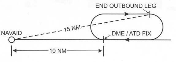
NOTE-
When the inbound course is toward the NAVAID, the fix distance is 10 NM, and the leg length is 5 NM, then the end of the outbound leg will be reached when the DME reads 15 NM.
FIG 5-3-6
Inbound Leg Away from NAVAID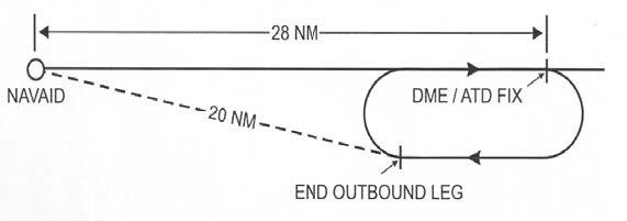
NOTE-
When the inbound course is away from the NAVAID and the fix distance is 28 NM, and the leg length is 8 NM, then the end of the outbound leg will be reached when the DME reads 20 NM.
-
Use of RNAV Distance in lieu of DME Distance. Substitution of RNAV computed distance to or from a NAVAID in place of DME distance is permitted when holding. However, the actual holding location and pattern flown will be further from the NAVAID than designed due to the lack of slant range in the position solution (see FIG 5-3-7). This may result in a slight difference between RNAV distance readout in reference to the NAVAID and the DME readout, especially at higher altitudes. When used solely for DME substitution, the difference between RNAV distance to/from a fix and DME slant range distance can be considered negligible and no pilot action is required.
REFERENCE-
AIM, Para 1-2-3, Use of Suitable Area Navigation (RNAV) Systems on Conventional Procedures and Routes.
FIG 5-3-7
Difference Between DME Distance From NAVAID & RNAV Computed Distance From NAVAID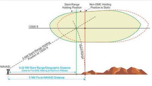
-
Use of RNAV Guidance and Holding. RNAV systems, including multi-sensor Flight Management Systems (FMS) and stand-alone GPS receivers, may be used to furnish lateral guidance when executing a hold. The manner in which holding is implemented in an RNAV system varies widely between aircraft and RNAV system manufacturers. Holding pattern data may be extracted from the RNAV database for published holds or may be manually entered for ad-hoc ATC-assigned holds. Pilots are expected to be familiar with the capabilities and limitations of the specific RNAV system used for holding.
-
All holding, including holding defined on an RNAV or RNP procedure, is based on the conventional NAVAID holding design criteria, including the holding protected airspace construction. There are differences between the holding entry and flight track assumed in conventional holding pattern design and the entry and track that may be flown when RNAV guidance is used to execute holding. Individually, these differences may not affect the ability of the aircraft to remain within holding pattern protected airspace. However, cumulatively, they can result in deviations sufficient to result in excursions up to limits of the holding pattern protected airspace, and in some circumstances beyond protected airspace. The following difference and considerations apply when an RNAV system furnishes the lateral guidance used to fly a holding pattern:
- Many systems use ground track angle instead of heading to select the entry method. While the holding pattern design allows a 5 degree tolerance, this may result in an unexpected entry when the winds induce a large drift angle.
- The holding protected airspace is based on the assumption that the aircraft will fly-over the holding fix upon initial entry. RNAV systems may execute a “fly-by” turn when approaching the holding fix prior to entry. A “fly-by” turn during a direct entry from the holding pattern side of holding course may result in excursions beyond protected airspace, especially as the intercept angle and ground speed increase.
- During holding, RNAV systems furnish lateral steering guidance using either a constant bank or constant radius to achieve the desired inbound and outbound turns. An aircraft's flight guidance system may use reduced bank angles for all turns including turns in holding, especially at higher altitudes, that may result in exceeding holding protected airspace. Use of a shallower bank angle will expand both the width and length of the aircraft track, especially as wind speed increases. If the flight guidance system's bank angle limit feature is pilot-selectable, a minimum 25 degree bank angle should be selected regardless of altitude unless aircraft operating limitations specify otherwise and the pilot advises ATC.
-
Where a holding distance is published, the turn from the outbound leg begins at the published distance from the holding fix, thus establishing the design turn point required to remain within protected airspace. RNAV systems apply a database coded or pilot-entered leg distance as a maximum length of the inbound leg to the holding fix. The RNAV system then calculates a turn point from the outbound leg required to achieve this inbound leg length. This often results in an RNAV-calculated turn point on the outbound leg beyond the design turn point. (See FIG 5-3-8). With a strong headwind against the outbound leg, RNAV systems may fly up to and possibly beyond the limits of protected airspace before turning inbound. (See FIG 5-3-9.) This is especially true at higher altitudes where wind speeds are greater and ground speed results in a wider holding pattern.
FIG 5-3-8
RNAV Lateral Guidance and Holding - No Wind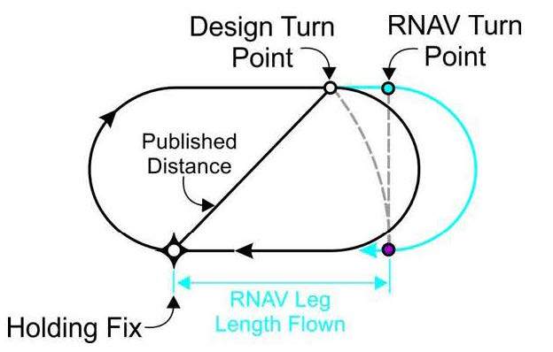
FIG 5-3-9
RNAV Lateral Guidance and Holding - Effect of Wind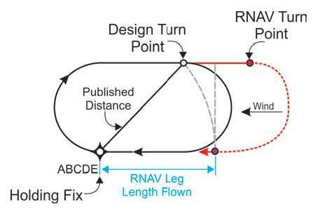
-
Some RNAV systems compute the holding pattern based on the aircraft's altitude and speed at a point prior to entering the hold. If the indicated airspeed is not reduced to comply with the maximum holding speed before this point, the computed pattern may exceed the protected airspace. Loading or executing a holding pattern may result in the speed and time limits applicable to the aircraft's current altitude being used to define the holding pattern for RNAV lateral guidance. This may result in an incorrect hold being flown by the RNAV system. For example, entering or executing the holding pattern above 14,000 feet when intending to hold below 14,000 feet may result in applying 1 ½ minute timing below 14,000 feet.
NOTE-
Some systems permit the pilot to modify leg time of holding patterns defined in the navigation database; for example, a hold-in-lieu of procedure turn. In most RNAV systems, the holding pattern time remains at the pilot-modified time and will not revert back to the coded time if the aircraft descends to a lower altitude where a shorter time interval applies.
- RNAV systems are not able to alert the pilot for excursions outside of holding pattern protected airspace since the dimensions of this airspace are not included in the navigation database. In addition, the dimensions of holding pattern protected airspace vary with altitude for a charted holding pattern, even when the hold is used for the same application. Close adherence to the pilot actions described in this section reduce the likelihood of exceeding the boundary of holding pattern protected airspace when using RNAV lateral guidance to conduct holding.
-
Holding patterns may be stored in the RNAV system's navigation database and include coding with parameters defining how the RNAV system will conduct the hold. For example, coding will determine whether holding is conducted to manual termination (HM), continued holding until the aircraft reaches a specified altitude (HA), or holding is conducted until the holding fix is crossed the first time after entry (HF). Some systems do not store all holding patterns, and may only store patterns associated with missed approaches and hold-in-lieu of procedure turn (HILPT). Some store all holding as standard patterns and require pilot action to conduct non-standard holding (left turns).
- Pilots are cautioned that multiple holding patterns may be established at the same fix. These holding patterns may differ in respect to turn directions and leg lengths depending on their application as an en route holding pattern, a holding pattern charted on a SID or STAR, or when used on an instrument approach procedure. Many RNAV systems limit the database coding at a particular fix to a single holding pattern definition. Pilots extracting the holding pattern from the navigation database are responsible for confirming that the holding pattern conforms to the assigned charted holding pattern in terms of turn direction, speed limit, timing, and distance.
- If ATC assigns holding that is not charted, then the pilot is responsible for programming the RNAV system with the assigned holding course, turn direction, speed limit, leg length, or leg time.
- Changes made after the initial execution may not apply until the next circuit of the holding pattern if the aircraft is in close proximity to the holding fix.
-
All holding, including holding defined on an RNAV or RNP procedure, is based on the conventional NAVAID holding design criteria, including the holding protected airspace construction. There are differences between the holding entry and flight track assumed in conventional holding pattern design and the entry and track that may be flown when RNAV guidance is used to execute holding. Individually, these differences may not affect the ability of the aircraft to remain within holding pattern protected airspace. However, cumulatively, they can result in deviations sufficient to result in excursions up to limits of the holding pattern protected airspace, and in some circumstances beyond protected airspace. The following difference and considerations apply when an RNAV system furnishes the lateral guidance used to fly a holding pattern:
-
Pilot Action. The following actions are recommended to ensure that the aircraft remains within holding protected airspace when holding is performed using either conventional NAVAID guidance or when using RNAV lateral guidance.
-
Speed. When ATC furnishes advance notice of holding, start speed reduction to be at or below the maximum holding speed allowed at least 3 minutes prior to crossing the holding fix. If advance notice by ATC is not provided, begin speed reduction as expeditiously as practical. It is acceptable to allow RNAV systems to determine an appropriate deceleration point prior to the holding fix and to manage the speed reduction to the RNAV computed holding speed. If the pilot does not permit the RNAV system to manage the deceleration from the computed point, the actual hold pattern size at holding entry may differ from the holding pattern size computed by the RNAV system.
-
Aircraft are expected to enter holding at or below the maximum holding speed established in paragraph 5-3-8j2(a) or the charted maximum holding speed.
- All fixed wing aircraft conducting holding should fly at speeds at or above 90 KIAS to minimize the influence of wind drift.
- When RNAV lateral guidance is used in fixed wing airplanes, it is desirable to enter and conduct holding at the lowest practical airspeed consistent with the airplane's recommended holding speed to address the cumulative errors associated with RNAV holding and increase the probability of remaining within protected airspace. It is acceptable to allow RNAV systems to determine a recommended holding speed that is at or below the maximum holding speed.
- Helicopter holding is based on a minimum airspeed of 90 KIAS.
-
Advise ATC immediately if unable to comply with the maximum holding airspeed and request an alternate clearance.
NOTE-
Speeds above the maximum or published holding speed may be necessary due to turbulence, icing, etc. Exceeding maximum holding airspeed may result in aircraft excursions beyond the holding pattern protected airspace. In a non-radar environment, the pilot should advise ATC that they cannot accept the assigned hold.
- Ensure the RNAV system applies the proper time and speed restrictions to a holding pattern. This is especially critical when climbing or descending to a holding pattern altitude where time and speed restrictions are different than at the present aircraft altitude.
-
Aircraft are expected to enter holding at or below the maximum holding speed established in paragraph 5-3-8j2(a) or the charted maximum holding speed.
-
Bank Angle. For holding not involving the use of RNAV lateral guidance, make all turns during entry and while holding at:
- 3 degrees per second, or
- 30 degree bank angle, or
-
25 degree bank angle, provided a flight director system is used.
NOTE-
Use whichever requires the least bank angle.
- When using RNAV lateral guidance to conduct holding, it is acceptable to permit the RNAV system to calculate the appropriate bank angle for the outbound and inbound turns. Do not use flight guidance system bank angle limiting functions of less than 25 degrees unless the feature is not pilot-selectable, required by the aircraft limitations, or its use is necessary to comply with the aircraft's minimum maneuvering speed margins. If the bank angle must be limited to less than 25 degrees, advise ATC that additional area for holding is required.
- Compensate for wind effect primarily by drift correction on the inbound and outbound legs. When outbound, triple the inbound drift correction to avoid major turning adjustments; for example, if correcting left by 8 degrees when inbound, correct right by 24 degrees when outbound.
- Determine entry turn from aircraft heading upon arrival at the holding fix; +/- 5 degrees in heading is considered to be within allowable good operating limits for determining entry. When using RNAV lateral guidance for holding, it is permissible to allow the system to compute the holding entry.
- RNAV lateral guidance may execute a fly-by turn beginning at an excessively large distance from the holding fix. Reducing speed to the maximum holding speed at least 3 minutes prior to reaching the holding fix and using the recommended 25 degree bank angle will reduce potential excursions beyond protected airspace.
- When RNAV guidance is used for holding, pilots should be prepared to intervene if the turn from outbound leg to the inbound leg does not begin within a reasonable distance of the charted leg length, especially when holding is used as a course reversal HILPT. Pilot intervention is not required when holding in an ATC-assigned holding pattern that is not charted. However, notify ATC when the outbound leg length becomes excessive when RNAV guidance is used for holding.
-
Speed. When ATC furnishes advance notice of holding, start speed reduction to be at or below the maximum holding speed allowed at least 3 minutes prior to crossing the holding fix. If advance notice by ATC is not provided, begin speed reduction as expeditiously as practical. It is acceptable to allow RNAV systems to determine an appropriate deceleration point prior to the holding fix and to manage the speed reduction to the RNAV computed holding speed. If the pilot does not permit the RNAV system to manage the deceleration from the computed point, the actual hold pattern size at holding entry may differ from the holding pattern size computed by the RNAV system.
-
Descriptive Terms.
- When holding at a fix and instructions are received specifying the time of departure from the fix, the pilot should adjust the aircraft's flight path within the limits of the established holding pattern in order to leave the fix at the exact time specified. After departing the holding fix, normal speed is to be resumed with respect to other governing speed requirements, such as terminal area speed limits, specific ATC requests, etc. Where the fix is associated with an instrument approach and timed approaches are in effect, a procedure turn must not be executed unless the pilot advises ATC, since aircraft holding are expected to proceed inbound on final approach directly from the holding pattern when approach clearance is received.
-
Radar surveillance of holding pattern airspace areas.
- Whenever aircraft are holding, ATC will usually provide radar surveillance of the holding airspace on the controller's radar display.
-
The controller will attempt to detect any holding aircraft that stray outside the holding airspace and will assist any detected aircraft to return to the assigned airspace.
NOTE-
Many factors could prevent ATC from providing this additional service, such as workload, number of targets, precipitation, ground clutter, and radar system capability. These circumstances may make it unfeasible to maintain radar identification of aircraft to detect aircraft straying from the holding pattern. The provision of this service depends entirely upon whether controllers believe they are in a position to provide it and does not relieve a pilot of their responsibility to adhere to an accepted ATC clearance.
- ATC is responsible for traffic and obstruction separation when they have assigned holding that is not associated with a published (charted) holding pattern. Altitudes assigned will be at or above the minimum vectoring or minimum IFR altitude.
- If an aircraft is established in a published holding pattern at an assigned altitude above the published minimum holding altitude and subsequently cleared for the approach, the pilot may descend to the published minimum holding altitude. The holding pattern would only be a segment of the IAP if it is published on the instrument procedure chart and is used in lieu of a procedure turn.
- For those holding patterns where there are no published minimum holding altitudes, the pilot, upon receiving an approach clearance, must maintain the last assigned altitude until leaving the holding pattern and established on the inbound course. Thereafter, the published minimum altitude of the route segment being flown will apply. It is expected that the pilot will be assigned a holding altitude that will permit a normal descent on the inbound course.
-
Whenever an aircraft is cleared to a fix other than the destination airport and delay is expected, it is the responsibility of ATC to issue complete holding instructions (unless the pattern is charted), an EFC time and best estimate of any additional en route/terminal delay.