You have 0 items in your cart

Section 1. Navigation Aids
-
General
- Various types of air navigation aids are in use today, each serving a special purpose. These aids have varied owners and operators, namely: the Federal Aviation Administration (FAA), the military services, private organizations, individual states and foreign governments. The FAA has the statutory authority to establish, operate, maintain air navigation facilities and to prescribe standards for the operation of any of these aids which are used for instrument flight in federally controlled airspace. These aids are tabulated in the Chart Supplement.
- Pilots should be aware of the possibility of momentary erroneous indications on cockpit displays when the primary signal generator for a ground-based navigational transmitter (for example, a glideslope, VOR, or nondirectional beacon) is inoperative. Pilots should disregard any navigation indication, regardless of its apparent validity, if the particular transmitter was identified by NOTAM or otherwise as unusable or inoperative.
-
Nondirectional Radio Beacon (NDB)
- A low or medium frequency radio beacon transmits nondirectional signals whereby the pilot of an aircraft properly equipped can determine bearings and “home” on the station. These facilities normally operate in a frequency band of 190 to 535 kilohertz (kHz), according to ICAO Annex 10 the frequency range for NDBs is between 190 and 1750 kHz, and transmit a continuous carrier with either 400 or 1020 hertz (Hz) modulation. All radio beacons except the compass locators transmit a continuous three-letter identification in code except during voice transmissions.
- When a radio beacon is used in conjunction with the Instrument Landing System markers, it is called a Compass Locator.
- Voice transmissions are made on radio beacons unless the letter “W” (without voice) is included in the class designator (HW).
- Radio beacons are subject to disturbances that may result in erroneous bearing information. Such disturbances result from such factors as lightning, precipitation static, etc. At night, radio beacons are vulnerable to interference from distant stations. Nearly all disturbances which affect the Automatic Direction Finder (ADF) bearing also affect the facility's identification. Noisy identification usually occurs when the ADF needle is erratic. Voice, music or erroneous identification may be heard when a steady false bearing is being displayed. Since ADF receivers do not have a “flag” to warn the pilot when erroneous bearing information is being displayed, the pilot should continuously monitor the NDB's identification.
-
VHF Omni-directional Range (VOR)
-
VORs operate within the 108.0 to 117.95 MHz frequency band and have a power output necessary to provide coverage within their assigned operational service volume. They are subject to line-of-sight restrictions, and the range varies proportionally to the altitude of the receiving equipment.
NOTE-
Normal service ranges for the various classes of VORs are given in Navigational Aid (NAVAID) Service Volumes, Paragraph 1-1-8.
- Most VORs are equipped for voice transmission on the VOR frequency. VORs without voice capability are indicated by the letter “W” (without voice) included in the class designator (VORW).
- The only positive method of identifying a VOR is by its Morse Code identification or by the recorded automatic voice identification which is always indicated by use of the word “VOR” following the range's name. Reliance on determining the identification of an omnirange should never be placed on listening to voice transmissions by the Flight Service Station (FSS) (or approach control facility) involved. Many FSSs remotely operate several omniranges with different names. In some cases, none of the VORs have the name of the “parent” FSS. During periods of maintenance, the facility may radiate a T-E-S-T code (- ● ●●● -) or the code may be removed. Some VOR equipment decodes the identifier and displays it to the pilot for verification to charts, while other equipment simply displays the expected identifier from a database to aid in verification to the audio tones. You should be familiar with your equipment and use it appropriately. If your equipment automatically decodes the identifier, it is not necessary to listen to the audio identification.
- Voice identification has been added to numerous VORs. The transmission consists of a voice announcement, “AIRVILLE VOR” alternating with the usual Morse Code identification.
-
The effectiveness of the VOR depends upon proper use and adjustment of both ground and airborne equipment.
- Accuracy. The accuracy of course alignment of the VOR is excellent, being generally plus or minus 1 degree.
-
Roughness. On some VORs, minor course roughness may be observed, evidenced by course needle or brief flag alarm activity (some receivers are more susceptible to these irregularities than others). At a few stations, usually in mountainous terrain, the pilot may occasionally observe a brief course needle oscillation, similar to the indication of “approaching station.” Pilots flying over unfamiliar routes are cautioned to be on the alert for these vagaries, and in particular, to use the “to/from” indicator to determine positive station passage.
- Certain propeller revolutions per minute (RPM) settings or helicopter rotor speeds can cause the VOR Course Deviation Indicator to fluctuate as much as plus or minus six degrees. Slight changes to the RPM setting will normally smooth out this roughness. Pilots are urged to check for this modulation phenomenon prior to reporting a VOR station or aircraft equipment for unsatisfactory operation.
-
The VOR Minimum Operational Network (MON). As flight procedures and route structure based on VORs are gradually being replaced with Performance-Based Navigation (PBN) procedures, the FAA is removing selected VORs from service. PBN procedures are primarily enabled by GPS and its augmentation systems, collectively referred to as Global Navigation Satellite System (GNSS). Aircraft that carry DME/DME equipment can also use RNAV which provides a backup to continue flying PBN during a GNSS disruption. For those aircraft that do not carry DME/DME, the FAA is retaining a limited network of VORs, called the VOR MON, to provide a basic conventional navigation service for operators to use if GNSS becomes unavailable. During a GNSS disruption, the MON will enable aircraft to navigate through the affected area or to a safe landing at a MON airport without reliance on GNSS. Navigation using the MON will not be as efficient as the new PBN route structure, but use of the MON will provide nearly continuous VOR signal coverage at 5,000 feet AGL across the NAS, outside of the Western U.S. Mountainous Area (WUSMA).
NOTE-
There is no plan to change the NAVAID and route structure in the WUSMA.
The VOR MON has been retained principally for IFR aircraft that are not equipped with DME/DME avionics. However, VFR aircraft may use the MON as desired. Aircraft equipped with DME/DME navigation systems would, in most cases, use DME/DME to continue flight using RNAV to their destination. However, these aircraft may, of course, use the MON.-
Distance to a MON airport. The VOR MON will ensure that regardless of an aircraft's position in the contiguous United States (CONUS), a MON airport (equipped with legacy ILS or VOR approaches) will be within 100 nautical miles. These airports are referred to as “MON airports” and will have an ILS approach or a VOR approach if an ILS is not available. VORs to support these approaches will be retained in the VOR MON. MON airports are charted on low-altitude en route charts and are contained in the Chart Supplement U.S. and other appropriate publications.
NOTE-
Any suitable airport can be used to land in the event of a VOR outage. For example, an airport with a DME-required ILS approach may be available and could be used by aircraft that are equipped with DME. The intent of the MON airport is to provide an approach that can be used by aircraft without ADF or DME when radar may not be available.
- Navigating to an airport. The VOR MON will retain sufficient VORs and increase VOR service volume to ensure that pilots will have nearly continuous signal reception of a VOR when flying at 5,000 feet AGL. A key concept of the MON is to ensure that an aircraft will always be within 100 NM of anairport with an instrument approach that is not dependent on GPS. (See paragraph 1-1-8.) If the pilot encounters a GPS outage, the pilot will be able to proceed via VOR-to-VOR navigation at 5,000 feet AGL through the GPS outage area or to a safe landing at a MON airport or another suitable airport, as appropriate. Nearly all VORs inside of the WUSMA and outside the CONUS are being retained. In these areas, pilots use the existing (Victor and Jet) route structure and VORs to proceed through a GPS outage or to a landing.
-
Using the VOR MON.
-
In the case of a planned GPS outage (for example, one that is in a published NOTAM), pilots may plan to fly through the outage using the MON as appropriate and as cleared by ATC. Similarly, aircraft not equipped with GPS may plan to fly and land using the MON, as appropriate and as cleared by ATC.
NOTE-
In many cases, flying using the MON may involve a more circuitous route than flying GPS-enabled RNAV.
-
In the case of an unscheduled GPS outage, pilots and ATC will need to coordinate the best outcome for all aircraft. It is possible that a GPS outage could be disruptive, causing high workload and demand for ATC service. Generally, the VOR MON concept will enable pilots to navigate through the GPS outage or land at a MON airport or at another airport that may have an appropriate approach or may be in visual conditions.
- The VOR MON is a reversionary service provided by the FAA for use by aircraft that are unable to continue RNAV during a GPS disruption. The FAA has not mandated that preflight or inflight planning include provisions for GPS- or WAAS-equipped aircraft to carry sufficient fuel to proceed to a MON airport in case of an unforeseen GPS outage. Specifically, flying to a MON airport as a filed alternate will not be explicitly required. Of course, consideration for the possibility of a GPS outage is prudent during flight planning as is maintaining proficiency with VOR navigation.
-
Also, in case of a GPS outage, pilots may coordinate with ATC and elect to continue through the outage or land. The VOR MON is designed to ensure that an aircraft is within 100 NM of an airport, but pilots may decide to proceed to any appropriate airport where a landing can be made. WAAS users flying under part 91 are not required to carry VOR avionics. These users do not have the ability or requirement to use the VOR MON. Prudent flight planning, by these WAAS-only aircraft, should consider the possibility of a GPS outage.
NOTE-
The FAA recognizes that non-GPS-based approaches will be reduced when VORs are eliminated, and that most airports with an instrument approach may only have GPS- or WAAS-based approaches. Pilots flying GPS- or WAAS-equipped aircraft that also have VOR/ILS avionics should be diligent to maintain proficiency in VOR and ILS approaches in the event of a GPS outage.
-
In the case of a planned GPS outage (for example, one that is in a published NOTAM), pilots may plan to fly through the outage using the MON as appropriate and as cleared by ATC. Similarly, aircraft not equipped with GPS may plan to fly and land using the MON, as appropriate and as cleared by ATC.
-
Distance to a MON airport. The VOR MON will ensure that regardless of an aircraft's position in the contiguous United States (CONUS), a MON airport (equipped with legacy ILS or VOR approaches) will be within 100 nautical miles. These airports are referred to as “MON airports” and will have an ILS approach or a VOR approach if an ILS is not available. VORs to support these approaches will be retained in the VOR MON. MON airports are charted on low-altitude en route charts and are contained in the Chart Supplement U.S. and other appropriate publications.
-
VORs operate within the 108.0 to 117.95 MHz frequency band and have a power output necessary to provide coverage within their assigned operational service volume. They are subject to line-of-sight restrictions, and the range varies proportionally to the altitude of the receiving equipment.
-
VOR Receiver Check
- The FAA VOR test facility (VOT) transmits a test signal which provides users a convenient means to determine the operational status and accuracy of a VOR receiver while on the ground where a VOT is located. The airborne use of VOT is permitted; however, its use is strictly limited to those areas/altitudes specifically authorized in the Chart Supplement or appropriate supplement.
- To use the VOT service, tune in the VOT frequency on your VOR receiver. With the Course Deviation Indicator (CDI) centered, the omni-bearing selector should read 0 degrees with the to/from indication showing “from” or the omni-bearing selector should read 180 degrees with the to/from indication showing “to.” Should the VOR receiver operate an RMI (Radio Magnetic Indicator), it will indicate 180 degrees on any omni-bearing selector (OBS) setting. Two means of identification are used. One is a series of dots and the other is a continuous tone. Information concerning an individual test signal can be obtained from the local FSS.
- Periodic VOR receiver calibration is most important. If a receiver's Automatic Gain Control or modulation circuit deteriorates, it is possible for it to display acceptable accuracy and sensitivity close into the VOR or VOT and display out-of-tolerance readings when located at greater distances where weaker signal areas exist. The likelihood of this deterioration varies between receivers, and is generally considered a function of time. The best assurance of having an accurate receiver is periodic calibration. Yearly intervals are recommended at which time an authorized repair facility should recalibrate the receiver to the manufacturer's specifications.
-
Federal Aviation Regulations (14 CFR section 91.171) provides for certain VOR equipment accuracy checks prior to flight under instrument flight rules. To comply with this requirement and to ensure satisfactory operation of the airborne system, the FAA has provided pilots with the following means of checking VOR receiver accuracy:
- VOT or a radiated test signal from an appropriately rated radio repair station.
- Certified airborne checkpoints and airways.
- Certified checkpoints on the airport surface.
- If an airborne checkpoint is not available, select an established VOR airway. Select a prominent ground point, preferably more than 20 NM from the VOR ground facility and maneuver the aircraft directly over the point at a reasonably low altitude above terrain and obstructions.
-
A radiated VOT from an appropriately rated radio repair station serves the same purpose as an FAA VOR signal and the check is made in much the same manner as a VOT with the following differences:
- The frequency normally approved by the Federal Communications Commission is 108.0 MHz.
- Repair stations are not permitted to radiate the VOR test signal continuously; consequently, the owner or operator must make arrangements with the repair station to have the test signal transmitted. This service is not provided by all radio repair stations. The aircraft owner or operator must determine which repair station in the local area provides this service. A representative of the repair station must make an entry into the aircraft logbook or other permanent record certifying to the radial accuracy and the date of transmission. The owner, operator or representative of the repair station may accomplish the necessary checks in the aircraft and make a logbook entry stating the results. It is necessary to verify which test radial is being transmitted and whether you should get a “to” or “from” indication.
-
Airborne and ground check points consist of certified radials that should be received at specific points on the airport surface or over specific landmarks while airborne in the immediate vicinity of the airport.
-
Should an error in excess of plus or minus 4 degrees be indicated through use of a ground check, or plus or minus 6 degrees using the airborne check, Instrument Flight Rules (IFR) flight must not be attempted without first correcting the source of the error.
CAUTION-
No correction other than the correction card figures supplied by the manufacturer should be applied in making these VOR receiver checks.
- Locations of airborne check points, ground check points and VOTs are published in the Chart Supplement.
- If a dual system VOR (units independent of each other except for the antenna) is installed in the aircraft, one system may be checked against the other. Turn both systems to the same VOR ground facility and note the indicated bearing to that station. The maximum permissible variations between the two indicated bearings is 4 degrees.
-
Should an error in excess of plus or minus 4 degrees be indicated through use of a ground check, or plus or minus 6 degrees using the airborne check, Instrument Flight Rules (IFR) flight must not be attempted without first correcting the source of the error.
-
Tactical Air Navigation (TACAN)
- For reasons peculiar to military or naval operations (unusual siting conditions, the pitching and rolling of a naval vessel, etc.) the civil VOR/Distance Measuring Equipment (DME) system of air navigation was considered unsuitable for military or naval use. A new navigational system, TACAN, was therefore developed by the military and naval forces to more readily lend itself to military and naval requirements. As a result, the FAA has integrated TACAN facilities with the civil VOR/DME program. Although the theoretical, or technical principles of operation of TACAN equipment are quite different from those of VOR/DME facilities, the end result, as far as the navigating pilot is concerned, is the same. These integrated facilities are called VORTACs.
- TACAN ground equipment consists of either a fixed or mobile transmitting unit. The airborne unit in conjunction with the ground unit reduces the transmitted signal to a visual presentation of both azimuth and distance information. TACAN is a pulse system and operates in the Ultrahigh Frequency (UHF) band of frequencies. Its use requires TACAN airborne equipment and does not operate through conventional VOR equipment.
-
VHF Omni-directional Range/Tactical Air Navigation (VORTAC)
- A VORTAC is a facility consisting of two components, VOR and TACAN, which provides three individual services: VOR azimuth, TACAN azimuth and TACAN distance (DME) at one site. Although consisting of more than one component, incorporating more than one operating frequency, and using more than one antenna system, a VORTAC is considered to be a unified navigational aid. Both components of a VORTAC are envisioned as operating simultaneously and providing the three services at all times.
- Transmitted signals of VOR and TACAN are each identified by three-letter code transmission and are interlocked so that pilots using VOR azimuth with TACAN distance can be assured that both signals being received are definitely from the same ground station. The frequency channels of the VOR and the TACAN at each VORTAC facility are “paired” in accordance with a national plan to simplify airborne operation.
-
Distance Measuring Equipment (DME)
- In the operation of DME, paired pulses at a specific spacing are sent out from the aircraft (this is the interrogation) and are received at the ground station. The ground station (transponder) then transmits paired pulses back to the aircraft at the same pulse spacing but on a different frequency. The time required for the round trip of this signal exchange is measured in the airborne DME unit and is translated into distance (nautical miles) from the aircraft to the ground station.
- Operating on the line-of-sight principle, DME furnishes distance information with a very high degree of accuracy. Reliable signals may be received at distances up to 199 NM at line-of-sight altitude with an accuracy of better than 1/2 mile or 3 percent of the distance, whichever is greater. Distance information received from DME equipment is SLANT RANGE distance and not actual horizontal distance.
- Operating frequency range of a DME according to ICAO Annex 10 is from 960 MHz to 1215 MHz. Aircraft equipped with TACAN equipment will receive distance information from a VORTAC automatically, while aircraft equipped with VOR must have a separate DME airborne unit.
- VOR/DME, VORTAC, Instrument Landing System (ILS)/DME, and localizer (LOC)/DME navigation facilities established by the FAA provide course and distance information from collocated components under a frequency pairing plan. Aircraft receiving equipment which provides for automatic DME selection assures reception of azimuth and distance information from a common source when designated VOR/DME, VORTAC, ILS/DME, and LOC/DME are selected.
- Due to the limited number of available frequencies, assignment of paired frequencies is required for certain military noncollocated VOR and TACAN facilities which serve the same area but which may be separated by distances up to a few miles.
- VOR/DME, VORTAC, ILS/DME, and LOC/DME facilities are identified by synchronized identifications which are transmitted on a time share basis. The VOR or localizer portion of the facility is identified by a coded tone modulated at 1020 Hz or a combination of code and voice. The TACAN or DME is identified by a coded tone modulated at 1350 Hz. The DME or TACAN coded identification is transmitted one time for each three or four times that the VOR or localizer coded identification is transmitted. When either the VOR or the DME is inoperative, it is important to recognize which identifier is retained for the operative facility. A single coded identification with a repetition interval of approximately 30 seconds indicates that the DME is operative.
- Aircraft equipment which provides for automatic DME selection assures reception of azimuth and distance information from a common source when designated VOR/DME, VORTAC and ILS/DME navigation facilities are selected. Pilots are cautioned to disregard any distance displays from automatically selected DME equipment when VOR or ILS facilities, which do not have the DME feature installed, are being used for position determination.
-
NAVAID Service Volumes
-
The FAA publishes Standard Service Volumes (SSVs) for most NAVAIDs. The SSV is a three-dimensional volume within which the FAA ensures that a signal can be received with adequate signal strength and course quality, and is free from interference from other NAVAIDs on similar frequencies (e.g., co-channel or adjacent-channel interference). However, the SSV signal protection does not include potential blockage from terrain or obstructions. The SSV is principally intended for off-route navigation, such as proceeding direct to or from a VOR when not on a published instrument procedure or route. Navigation on published instrument procedures (e.g., approaches or departures) or routes (e.g., Victor routes) may use NAVAIDs outside of the SSV, when Extended Service Volume (ESV) is approved, since adequate signal strength, course quality, and freedom from interference are verified by the FAA prior to the publishing of the instrument procedure or route.
NOTE-
A conical area directly above the NAVAID is generally not usable for navigation.
- A NAVAID will have service volume restrictions if it does not conform to signal strength and course quality standards throughout the published SSV. Service volume restrictions are first published in Notices to Airmen (NOTAMs) and then with the alphabetical listing of the NAVAIDs in the Chart Supplement. Service volume restrictions do not generally apply to published instrument procedures or routes unless published in NOTAMs for the affected instrument procedure or route.
-
VOR/DME/TACAN Standard Service Volumes (SSV).
-
The three original SSVs are shown in FIG 1-1-1 and are designated with three classes of NAVAIDs: Terminal (T), Low (L), and High (H). The usable distance of the NAVAID depends on the altitude Above the Transmitter Height (ATH) for each class. The lower edge of the usable distance when below 1,000 feet ATH is shown in FIG 1-1-2 for Terminal NAVAIDs and in FIG 1-1-3 for Low and High NAVAIDs.
FIG 1-1-1
Original Standard Service Volumes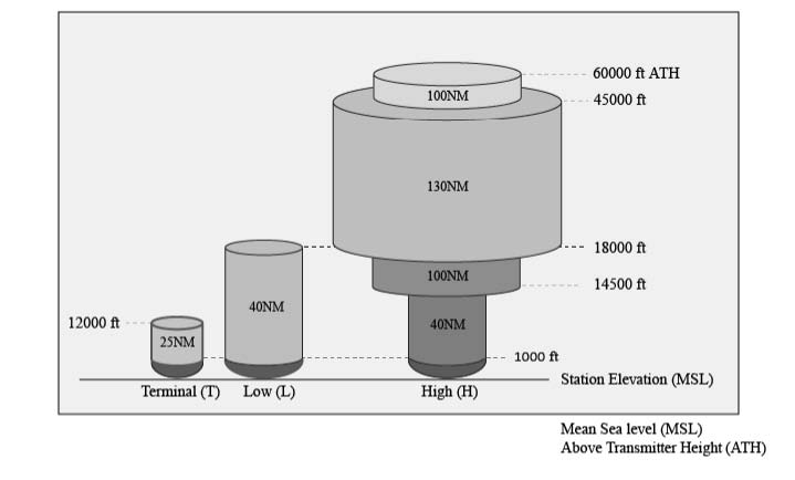
FIG 1-1-2
Lower Edge of the Terminal Service Volume (in altitude ATH)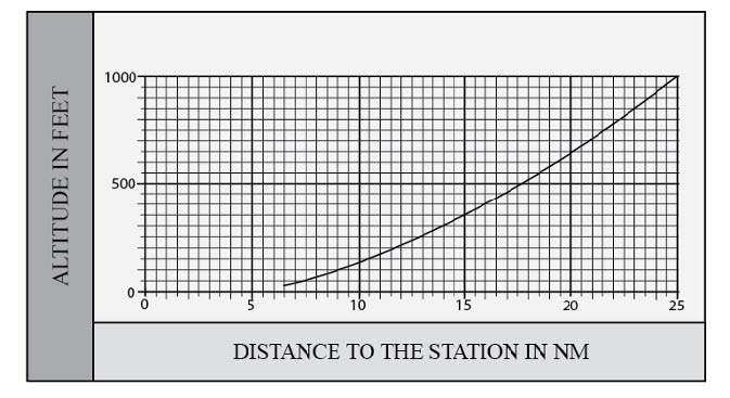
FIG 1-1-3
Lower Edge of Low and High Service Volumes (in altitude ATH)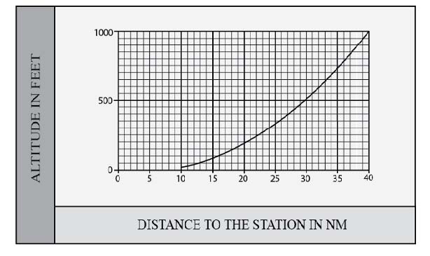
-
With the progression of navigation capabilities to Performance Based Navigation (PBN), additional capabilities for off-route navigation are necessary. For example, the VOR MON (See paragraph 1-1-3 f.) requires the use of VORs at 5,000 feet AGL, which is beyond the original SSV ranges. Additionally, PBN procedures using DME require extended ranges. As a result, the FAA created four additional SSVs. Two of the new SSVs are associated with VORs: VOR Low (VL) and VOR High (VH), as shown in FIG 1-1-4. The other two new SSVs are associated with DME: DME Low (DL) and DME High (DH), as shown in FIG 1-1-5. The SSV at altitudes below 1,000 feet for the VL and VH are the same as FIG 1-1-3. The SSVs at altitudes below 12,900 feet for the DL and DH SSVs correspond to a conservative estimate of the DME radio line of sight (RLOS) coverage at each altitude (not including possible terrain blockage).
FIG 1-1-4
New VOR Service Volumes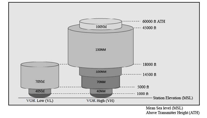
FIG 1-1-5
New DME Service Volumes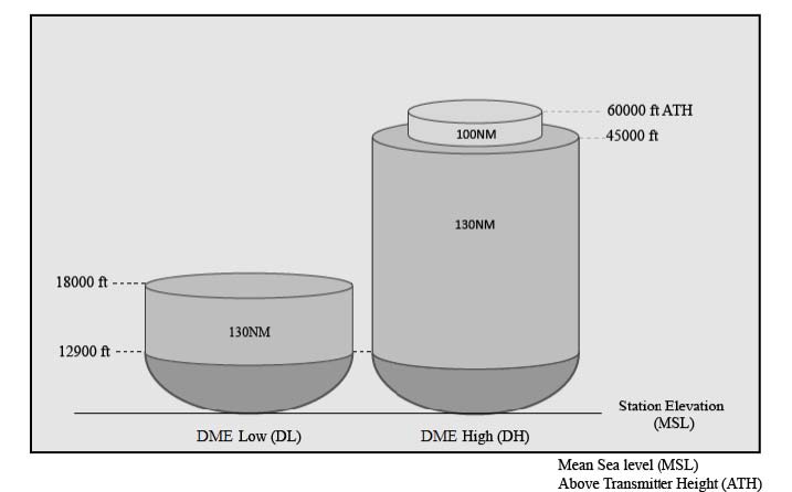
NOTE-
- In the past, NAVAIDs at one location typically all had the same SSV. For example, a VORTAC typically had a High (H) SSV for the VOR, the TACAN azimuth, and the TACAN DME, or a Low (L) or Terminal (T) SSV for all three. A VOR/DME typically had a High (H), Low (L), or Terminal (T) for both the VOR and the DME. A common SSV may no longer be the case at all locations. A VOR/DME, for example, could have an SSV of VL for the VOR and DH for the DME, or other combinations.
- The TACAN azimuth will only be classified as T, L, or H.
-
TBL 1-1-1 is a tabular summary of the VOR, DME, and TACAN NAVAID SSVs, not including altitudes below 1,000 feet ATH for VOR and TACAN Azimuth, and not including ranges for altitudes below 12,900 feet for TACAN and DME.
TBL 1-1-1
VOR/DME/TACAN Standard Service VolumesSSV Designator
Altitude and Range Boundaries
T (Terminal)
From 1,000 feet ATH up to and including 12,000 feet ATH at radial distances out to 25 NM.
L (Low Altitude)
From 1,000 feet ATH up to and including 18,000 feet ATH at radial distances out to 40 NM.
H (High Altitude)
From 1,000 feet ATH up to and including 14,500 feet ATH at radial distances out to 40 NM. From 14,500 ATH up to and including 60,000 feet at radial distances out to 100 NM. From 18,000 feet ATH up to and including 45,000 feet ATH at radial distances out to 130 NM.
VL (VOR Low)
From 1,000 feet ATH up to but not including 5,000 feet ATH at radial distances out to 40 NM. From 5,000 feet ATH up to but not including 18,000 feet ATH at radial distances out to 70 NM.
VH (VOR High)
From 1,000 feet ATH up to but not including 5,000 feet ATH at radial distances out to 40 NM. From 5,000 feet ATH up to but not including 14,500 feet ATH at radial distances out to 70 NM. From 14,500 ATH up to and including 60,000 feet at radial distances out to 100 NM. From 18,000 feet ATH up to and including 45,000 feet ATH at radial distances out to 130 NM.
DL (DME Low)
For altitudes up to 12,900 feet ATH at a radial distance corresponding to the LOS to the NAVAID. From 12,900 feet ATH up to but not including 18,000 feet ATH at radial distances out to 130 NM
DH (DME High)
For altitudes up to 12,900 feet ATH at a radial distance corresponding to the LOS to the NAVAID. From 12,900 ATH up to and including 60,000 feet at radial distances out to 100 NM. From 12,900 feet ATH up to and including 45,000 feet ATH at radial distances out to 130 NM.
-
The three original SSVs are shown in FIG 1-1-1 and are designated with three classes of NAVAIDs: Terminal (T), Low (L), and High (H). The usable distance of the NAVAID depends on the altitude Above the Transmitter Height (ATH) for each class. The lower edge of the usable distance when below 1,000 feet ATH is shown in FIG 1-1-2 for Terminal NAVAIDs and in FIG 1-1-3 for Low and High NAVAIDs.
-
Nondirectional Radio Beacon (NDB) SSVs. NDBs are classified according to their intended use. The ranges of NDB service volumes are shown in TBL 1-1-2. The distance (radius) is the same at all altitudes for each class.
TBL 1-1-2
NDB Service VolumesClass
Distance (Radius) (NM)
Compass Locator
15
MH
25
H
50*
HH
75
*Service ranges of individual facilities may be less than 50 nautical miles (NM). Restrictions to service volumes are first published as a Notice to Airmen and then with the alphabetical listing of the NAVAID in the Chart Supplement.
-
The FAA publishes Standard Service Volumes (SSVs) for most NAVAIDs. The SSV is a three-dimensional volume within which the FAA ensures that a signal can be received with adequate signal strength and course quality, and is free from interference from other NAVAIDs on similar frequencies (e.g., co-channel or adjacent-channel interference). However, the SSV signal protection does not include potential blockage from terrain or obstructions. The SSV is principally intended for off-route navigation, such as proceeding direct to or from a VOR when not on a published instrument procedure or route. Navigation on published instrument procedures (e.g., approaches or departures) or routes (e.g., Victor routes) may use NAVAIDs outside of the SSV, when Extended Service Volume (ESV) is approved, since adequate signal strength, course quality, and freedom from interference are verified by the FAA prior to the publishing of the instrument procedure or route.
-
Instrument Landing System (ILS)
-
General
- The ILS is designed to provide an approach path for exact alignment and descent of an aircraft on final approach to a runway.
- The basic components of an ILS are the localizer, glide slope, and Outer Marker (OM) and, when installed for use with Category II or Category III instrument approach procedures, an Inner Marker (IM).
-
The system may be divided functionally into three parts:
- Guidance information:localizer, glide slope.
- Range information: marker beacon, DME.
- Visual information:approach lights, touchdown and centerline lights, runway lights.
-
The following means may be used to substitute for the OM:
- Compass locator; or
- Precision Approach Radar (PAR); or
- Airport Surveillance Radar (ASR); or
- Distance Measuring Equipment (DME), Very High Frequency Omni-directional Range (VOR), or Nondirectional beacon fixes authorized in the Standard Instrument Approach Procedure; or
- Very High Frequency Omni-directional Radio Range (VOR); or
- Nondirectional beacon fixes authorized in the Standard Instrument Approach Procedure; or
- A suitable RNAV system with Global Positioning System (GPS), capable of fix identification on a Standard Instrument Approach Procedure.
- Where a complete ILS system is installed on each end of a runway; (i.e., the approach end of Runway 4 and the approach end of Runway 22) the ILS systems are not in service simultaneously.
-
Localizer
- The localizer transmitter operates on one of 40 ILS channels within the frequency range of 108.10 to 111.95 MHz. Signals provide the pilot with course guidance to the runway centerline.
- The approach course of the localizer is called the front course and is used with other functional parts, e.g., glide slope, marker beacons, etc. The localizer signal is transmitted at the far end of the runway. It is adjusted for a course width of (full scale fly-left to a full scale fly-right) of 700 feet at the runway threshold.
-
The course line along the extended centerline of a runway, in the opposite direction to the front course is called the back course.
CAUTION-
Unless the aircraft's ILS equipment includes reverse sensing capability, when flying inbound on the back course it is necessary to steer the aircraft in the direction opposite the needle deflection when making corrections from off-course to on-course. This “flying away from the needle” is also required when flying outbound on the front course of the localizer. Do not use back course signals for approach unless a back course approach procedure is published for that particular runway and the approach is authorized by ATC.
-
Identification is in International Morse Code and consists of a three-letter identifier preceded by the letter I (●●) transmitted on the localizer frequency.
EXAMPLE-
I-DIA
-
The localizer provides course guidance throughout the descent path to the runway threshold from a distance of 18 NM from the antenna between an altitude of 1,000 feet above the highest terrain along the course line and 4,500 feet above the elevation of the antenna site. Proper off-course indications are provided throughout the following angular areas of the operational service volume:
- To 10 degrees either side of the course along a radius of 18 NM from the antenna; and
-
From 10 to 35 degrees either side of the course along a radius of 10 NM. (See FIG 1-1-6.)
FIG 1-1-6
Limits of Localizer Coverage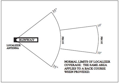
- Unreliable signals may be received outside of these areas. ATC may clear aircraft on procedures beyond the service volume when the controller initiates the action or when the pilot requests, and radar monitoring is provided.
-
The areas described in paragraph 1-1-9 b5 and depicted in FIG 1-1-6 represent a Standard Service Volume (SSV) localizer. All charted procedures with localizer coverage beyond the 18 NM SSV have been through the approval process for Expanded Service Volume (ESV), and have been validated by flight inspection. (See FIG 1-1-7.)
FIG 1-1-7
ILS Expanded Service Volume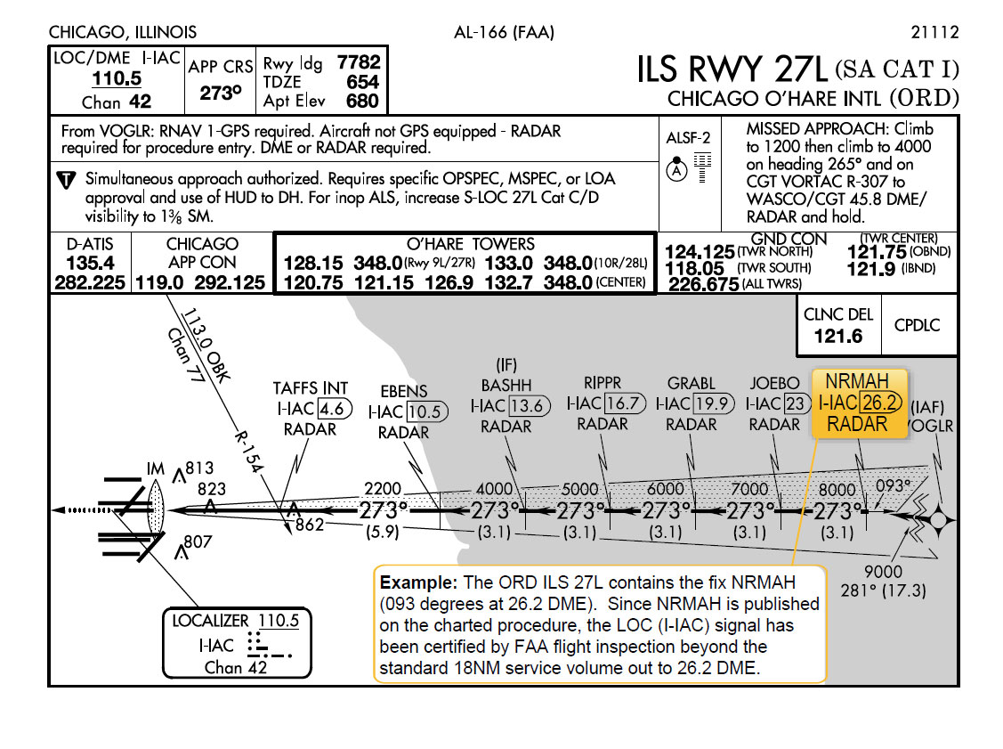
-
Localizer Type Directional Aid (LDA)
- The LDA is of comparable use and accuracy to a localizer but is not part of a complete ILS. The LDA course usually provides a more precise approach course than the similar Simplified Directional Facility (SDF) installation, which may have a course width of 6 or 12 degrees.
- The LDA is not aligned with the runway. Straight-in minimums may be published where alignment does not exceed 30 degrees between the course and runway. Circling minimums only are published where this alignment exceeds 30 degrees.
- A very limited number of LDA approaches also incorporate a glideslope. These are annotated in the plan view of the instrument approach chart with a note, “LDA/Glideslope.” These procedures fall under a newly defined category of approaches called Approach with Vertical Guidance (APV) described in paragraph 5-4-5, Instrument Approach Procedure Charts, subparagraph a7(b), Approach with Vertical Guidance (APV). LDA minima for with and without glideslope is provided and annotated on the minima lines of the approach chart as S-LDA/GS and S-LDA. Because the final approach course is not aligned with the runway centerline, additional maneuvering will be required compared to an ILS approach.
-
Glide Slope/Glide Path
-
The UHF glide slope transmitter, operating on one of the 40 ILS channels within the frequency range 329.15 MHz, to 335.00 MHz radiates its signals in the direction of the localizer front course. The term “glide path” means that portion of the glide slope that intersects the localizer.
CAUTION-
False glide slope signals may exist in the area of the localizer back course approach which can cause the glide slope flag alarm to disappear and present unreliable glide slope information. Disregard all glide slope signal indications when making a localizer back course approach unless a glide slope is specified on the approach and landing chart.
- The glide slope transmitter is located between 750 feet and 1,250 feet from the approach end of the runway (down the runway) and offset 250 to 650 feet from the runway centerline. It transmits a glide path beam 1.4 degrees wide (vertically). The signal provides descent information for navigation down to the lowest authorized decision height (DH) specified in the approved ILS approach procedure. The glidepath may not be suitable for navigation below the lowest authorized DH and any reference to glidepath indications below that height must be supplemented by visual reference to the runway environment. Glidepaths with no published DH are usable to runway threshold.
- The glide path projection angle is normally adjusted to 3 degrees above horizontal so that it intersects the MM at about 200 feet and the OM at about 1,400 feet above the runway elevation. The glide slope is normally usable to the distance of 10 NM. However, at some locations, the glide slope has been certified for an extended service volume which exceeds 10 NM.
- Pilots must be alert when approaching the glidepath interception. False courses and reverse sensing will occur at angles considerably greater than the published path.
-
Make every effort to remain on the indicated glide path.
CAUTION-
Avoid flying below the glide path to assure obstacle/terrain clearance is maintained.
- The published glide slope threshold crossing height (TCH) DOES NOT represent the height of the actual glide path on-course indication above the runway threshold. It is used as a reference for planning purposes which represents the height above the runway threshold that an aircraft's glide slope antenna should be, if that aircraft remains on a trajectory formed by the four-mile-to-middle marker glidepath segment.
-
Pilots must be aware of the vertical height between the aircraft's glide slope antenna and the main gear in the landing configuration and, at the DH, plan to adjust the descent angle accordingly if the published TCH indicates the wheel crossing height over the runway threshold may not be satisfactory. Tests indicate a comfortable wheel crossing height is approximately 20 to 30 feet, depending on the type of aircraft.
NOTE-
The TCH for a runway is established based on several factors including the largest aircraft category that normally uses the runway, how airport layout affects the glide slope antenna placement, and terrain. A higher than optimum TCH, with the same glide path angle, may cause the aircraft to touch down further from the threshold if the trajectory of the approach is maintained until the flare. Pilots should consider the effect of a high TCH on the runway available for stopping the aircraft.
-
The UHF glide slope transmitter, operating on one of the 40 ILS channels within the frequency range 329.15 MHz, to 335.00 MHz radiates its signals in the direction of the localizer front course. The term “glide path” means that portion of the glide slope that intersects the localizer.
- Distance Measuring Equipment (DME)
-
Marker Beacon
- ILS marker beacons have a rated power output of 3 watts or less and an antenna array designed to produce an elliptical pattern with dimensions, at 1,000 feet above the antenna, of approximately 2,400 feet in width and 4,200 feet in length. Airborne marker beacon receivers with a selective sensitivity feature should always be operated in the “low” sensitivity position for proper reception of ILS marker beacons.
-
ILS systems may have an associated OM. An MM is no longer required. Locations with a Category II ILS also have an Inner Marker (IM). Due to advances in both ground navigation equipment and airborne avionics, as well as the numerous means that may be used as a substitute for a marker beacon, the current requirements for the use of marker beacons are:
- An OM or suitable substitute identifies the Final Approach Fix (FAF) for nonprecision approach (NPA) operations (for example, localizer only); and
- The MM indicates a position approximately 3,500 feet from the landing threshold. This is also the position where an aircraft on the glide path will be at an altitude of approximately 200 feet above the elevation of the touchdown zone. A MM is no longer operationally required. There are some MMs still in use, but there are no MMs being installed at new ILS sites by the FAA; and
-
An IM, where installed, indicates the point at which an aircraft is at decision height on the glide path during a Category II ILS approach. An IM is only required for CAT II operations that do not have a published radio altitude (RA) minimum.
TBL 1-1-3
Marker Passage IndicationsMarker
Code
Light
OM
− − −
BLUE
MM
● − ● −
AMBER
IM
● ● ● ●
WHITE
BC
● ● ● ●
WHITE
- A back course marker normally indicates the ILS back course final approach fix where approach descent is commenced.
-
Compass Locator
- Compass locator transmitters are often situated at the MM and OM sites. The transmitters have a power of less than 25 watts, a range of at least 15 miles and operate between 190 and 535 kHz. At some locations, higher powered radio beacons, up to 400 watts, are used as OM compass locators.
- Compass locators transmit two letter identification groups. The outer locator transmits the first two letters of the localizer identification group, and the middle locator transmits the last two letters of the localizer identification group.
-
ILS Frequency (See TBL 1-1-4.)
TBL 1-1-4
Frequency Pairs Allocated for ILSLocalizer MHz
Glide Slope
108.10
334.70
108.15
334.55
108.3
334.10
108.35
333.95
108.5
329.90
108.55
329.75
108.7
330.50
108.75
330.35
108.9
329.30
108.95
329.15
109.1
331.40
109.15
331.25
109.3
332.00
109.35
331.85
109.50
332.60
109.55
332.45
109.70
333.20
109.75
333.05
109.90
333.80
109.95
333.65
110.1
334.40
110.15
334.25
110.3
335.00
110.35
334.85
110.5
329.60
110.55
329.45
110.70
330.20
110.75
330.05
110.90
330.80
110.95
330.65
111.10
331.70
111.15
331.55
111.30
332.30
111.35
332.15
111.50
332.9
111.55
332.75
111.70
333.5
111.75
333.35
111.90
331.1
111.95
330.95
-
ILS Minimums
-
The lowest authorized ILS minimums, with all required ground and airborne systems components operative, are:
- Category I. Decision Height (DH) 200 feet and Runway Visual Range (RVR) 2,400 feet (with touchdown zone and centerline lighting, RVR 1,800 feet), or (with Autopilot or FD or HUD, RVR 1,800 feet);
- Special Authorization Category I. DH 150 feet and Runway Visual Range (RVR) 1,400 feet, HUD to DH;
- Category II. DH 100 feet and RVR 1,200 feet (with autoland or HUD to touchdown and noted on authorization, RVR 1,000 feet);
- Special Authorization Category II with Reduced Lighting. DH 100 feet and RVR 1,200 feet with autoland or HUD to touchdown and noted on authorization (touchdown zone, centerline lighting, and ALSF-2 are not required);
- Category IIIa. No DH or DH below 100 feet and RVR not less than 700 feet;
- Category IIIb. No DH or DH below 50 feet and RVR less than 700 feet but not less than 150 feet; and
-
Category IIIc. No DH and no RVR limitation.
NOTE-
Special authorization and equipment required for Categories II and III.
-
The lowest authorized ILS minimums, with all required ground and airborne systems components operative, are:
-
Inoperative ILS Components
- Inoperative localizer. When the localizer fails, an ILS approach is not authorized.
-
Inoperative glide slope.When the glide slope fails, the ILS reverts to a non-precision localizer approach.
REFERENCE-
See the inoperative component table in the U.S. Government Terminal Procedures Publication (TPP), for adjustments to minimums due to inoperative airborne or ground system equipment.
-
ILS Course and Glideslope Distortion
- All pilots should be aware that ILS installations are subject to signal interference by surface vehicles and aircraft (either on the ground or airborne). ILS CRITICAL AREAS are established near each localizer and glide slope antenna. Pilots should be aware of the level of critical area protection they can expect in various weather conditions and understand that signal disturbances may occur as a result of normal airport operations irrespective of the official weather observation.
-
ATC is not always required to issue control instructions to avoid interfering operations within ILS critical areas at controlled airports during the hours the Airport Traffic Control Tower (ATCT) is in operation. ATC responsibilities vary depending on the official weather observation and are described as follows:
- Weather Conditions.Official weather observation indicates a ceiling of 800 feet or higher and visibility 2 miles or greater, no localizer or glideslope critical area protection is provided by ATC unless specifically requested by the flight crew.
-
Weather Conditions. Official weather observation indicates a ceiling of less than 800 feet or visibility less than 2 miles.
- Holding. Aircraft holding below 5,000 feet between the outer marker and the airport may cause localizer signal variations for aircraft conducting the ILS approach. Accordingly, such holding will not be authorized by ATC.
-
Localizer Critical Area. When an arriving aircraft is inside the outer marker (OM) or the fix used in lieu of the OM, vehicles and aircraft will not be authorized in or over the precision approach critical area except:
- A preceding arriving aircraft on the same or another runway may pass over or through the localizer critical area, and;
- A preceding departing aircraft or missed approach on the same or another runway may pass through or over the localizer critical area.
- Glide Slope Critical Area. ATC will not authorize vehicles or aircraft operations in or over the glideslope critical area when an arriving aircraft is inside the outer marker (OM), or the fix used in lieu of the OM, unless the arriving aircraft has reported the runway in sight and is circling or side‐stepping to land on another runway.
-
Weather Conditions. Official weather observation indicates a ceiling less than 200 feet or runway visual range (RVR) less than 2000 feet.
-
Localizer Critical Area. In addition to the critical area protection described in 1-1-9k2(b) above, when an arriving aircraft is inside the middle marker (MM), or in the absence of a MM, ½ mile final, ATC will not authorize:
- A preceding arriving aircraft on the same or another runway to pass over or through the localizer critical area, or;
- A preceding departing aircraft or missed approach on the same or another runway to pass through or over the localizer critical area.
-
Localizer Critical Area. In addition to the critical area protection described in 1-1-9k2(b) above, when an arriving aircraft is inside the middle marker (MM), or in the absence of a MM, ½ mile final, ATC will not authorize:
-
In order to ensure that pilot and controller expectations match with respect to critical area protection for a given approach and landing operation, a flight crew should advise the tower any time it intends to conduct any autoland operation or use an SA CAT I, any CAT II, or any CAT III line of minima anytime the official weather observation is at or above a ceiling of 800 feet and 2 miles visibility. If ATC is unable to protect the critical area, they will advise the flight crew.
EXAMPLE-
Denver Tower, United 1153, Request Autoland (runway) ATC replies with:
United 1153, Denver Tower, Roger, Critical Areas not protected. - Pilots are cautioned that even when the critical areas are considered to be protected, unless the official weather observation including controller observations indicates a ceiling less than 200 feet or RVR less than 2000 feet, ATC may still authorize a preceding arriving, departing, or missed approach aircraft to pass through or over the localizer critical area and that this may cause signal disturbances that could result in an undesired aircraft state during the final stages of the approach, landing, and rollout.
-
Pilots are cautioned that vehicular traffic not subject to ATC may cause momentary deviation to ILS course or glide slope signals. Also, critical areas are not protected at uncontrolled airports or at airports with an operating control tower when weather or visibility conditions are above those requiring protective measures. Aircraft conducting coupled or autoland operations should be especially alert in monitoring automatic flight control systems and be prepared to intervene as necessary. (See FIG 1-1-8.)
NOTE-
Unless otherwise coordinated through Flight Standards, ILS signals to Category I runways are not flight inspected below the point that is 100 feet less than the decision altitude (DA). Guidance signal anomalies may be encountered below this altitude.
-
General
-
Simplified Directional Facility (SDF)
- The SDF provides a final approach course similar to that of the ILS localizer. It does not provide glide slope information. A clear understanding of the ILS localizer and the additional factors listed below completely describe the operational characteristics and use of the SDF.
- The SDF transmits signals within the range of 108.10 to 111.95 MHz.
- The approach techniques and procedures used in an SDF instrument approach are essentially the same as those employed in executing a standard localizer approach except the SDF course may not be aligned with the runway and the course may be wider, resulting in less precision.
- Usable off-course indications are limited to 35 degrees either side of the course centerline. Instrument indications received beyond 35 degrees should be disregarded.
- The SDF antenna may be offset from the runway centerline. Because of this, the angle of convergence between the final approach course and the runway bearing should be determined by reference to the instrument approach procedure chart. This angle is generally not more than 3 degrees. However, it should be noted that inasmuch as the approach course originates at the antenna site, an approach which is continued beyond the runway threshold will lead the aircraft to the SDF offset position rather than along the runway centerline.
- The SDF signal is fixed at either 6 degrees or 12 degrees as necessary to provide maximum flyability and optimum course quality.
-
Identification consists of a three-letter identifier transmitted in Morse Code on the SDF frequency. The appropriate instrument approach chart will indicate the identifier used at a particular airport.
FIG 1-1-8
FAA Instrument Landing Systems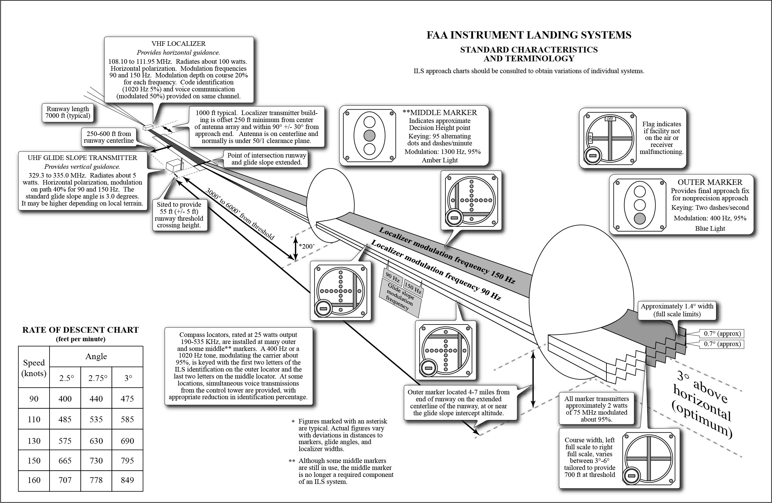
-
NAVAID Identifier Removal During Maintenance
During periods of routine or emergency maintenance, coded identification (or code and voice, where applicable) is removed from certain FAA NAVAIDs. Removal of identification serves as a warning to pilots that the facility is officially off the air for tune-up or repair and may be unreliable even though intermittent or constant signals are received.
NOTE-
During periods of maintenance VHF ranges may radiate a T-E-S-T code (- ● ●●● -).
NOTE-
DO NOT attempt to fly a procedure that is NOTAMed out of service even if the identification is present. In certain cases, the identification may be transmitted for short periods as part of the testing.
-
NAVAIDs with Voice
- Voice equipped en route radio navigational aids are under the operational control of either a Flight Service Station (FSS) or an approach control facility. Facilities with two-way voice communication available are indicated in the Chart Supplement and aeronautical charts.
- Unless otherwise noted on the chart, all radio navigation aids operate continuously except during shutdowns for maintenance. Hours of operation of facilities not operating continuously are annotated on charts and in the Chart Supplement.
-
User Reports Requested on NAVAID Outages
- Users of the National Airspace System (NAS) can render valuable assistance in the early correction of NAVAID malfunctions or GNSS problems and are encouraged to report their observations of undesirable avionics performance. Although NAVAIDs are monitored by electronic detectors, adverse effects of electronic interference, new obstructions, or changes in terrain near the NAVAID can exist without detection by the ground monitors. Some of the characteristics of malfunction or deteriorating performance which should be reported are: erratic course or bearing indications; intermittent, or full, flag alarm; garbled, missing or obviously improper coded identification; poor quality communications reception; or, in the case of frequency interference, an audible hum or tone accompanying radio communications or NAVAID identification. GNSS problems are often characterized by navigation degradation or service loss indications. For instance, pilots conducting operations in areas where there is GNSS interference may be unable to use GPS for navigation, and ADS-B may be unavailable for surveillance. Radio frequency interference may affect both navigation for the pilot and surveillance by the air traffic controller. Depending on the equipment and integration, either an advisory light or message may alert the pilot. Air traffic controllers monitoring ADS-B reports may stop receiving ADS-B position messages and associated aircraft tracks.
- Malfunctioning, faulty, inappropriately installed, operated, or modified GPS re-radiator systems, intended to be used for aircraft maintenance activities, have resulted in unintentional disruption of aviation GPS receivers. This type of disruption could result in unflagged, erroneous position-information output to primary flight displays/indicators and to other aircraft and air traffic control systems. Since Receiver Autonomous Integrity Monitoring (RAIM) is only partially effective against this type of disruption (effectively a “signal spoofing”), the pilot may not be aware of any erroneous navigation indications; ATC may be the only means available to identify these disruptions and detect unexpected aircraft positions while monitoring aircraft for IFR separation.
- Pilots encountering navigation error events should transition to another source of navigation and request amended clearances from ATC as necessary.
-
Pilots are encouraged to submit detailed reports of NAVAID or GPS anomaly as soon as practical. Pilot reports of navigation error events should contain the following information:
- Date and time the anomaly was observed, and NAVAID ID (or GPS).
- Location of the aircraft at the time the anomaly started and ended (e.g., latitude/longitude or bearing/distance from a reference point),
- Heading, altitude, type of aircraft (make/model/call sign),
- Type of avionics/receivers in use (e.g., make/model/software series or version),
- Number of satellites being tracked, if applicable,
- Description of the position/navigation/timing anomaly observed, and duration of the event,
- Consequences/operational impact(s) of the NAVAID or GPS anomaly,
- Actions taken to mitigate the anomaly and/or remedy provided by the ATC facility,
- Post flight pilot/maintenance actions taken.
-
Pilots operating an aircraft in controlled airspace under IFR shall comply with CFR § 91.187 and promptly report as soon as practical to ATC any malfunctions of navigational equipment occurring in flight; pilots should submit initial reports:
- Immediately, by radio to the controlling ATC facility or FSS.
- By telephone to the nearest ATC facility controlling the airspace where the disruption was experienced.
- Additionally, GPS problems should be reported, post flight, byInternet via the GPS Anomaly Reporting Form at http://www.faa.gov/air_traffic/nas/gps_reports/.
- To minimize ATC workload, GPS anomalies associated with known testing NOTAMs should NOT be reported in-flight to ATC in detail; EXCEPT when:
-
LORAN
NOTE-
In accordance with the 2010 DHS Appropriations Act, the U.S. Coast Guard (USCG) terminated the transmission of all U.S. LORAN-C signals on 08 Feb 2010. The USCG also terminated the transmission of the Russian American signals on 01 Aug 2010, and the Canadian LORAN-C signals on 03 Aug 2010. For more information, visit http://www.navcen.uscg.gov. Operators should also note that TSO-C60b, AIRBORNE AREA NAVIGATION EQUIPMENT USING LORAN-C INPUTS, has been canceled by the FAA.
-
Inertial Reference Unit (IRU), Inertial Navigation System (INS), and Attitude Heading Reference System (AHRS)
- IRUs are self-contained systems comprised of gyros and accelerometers that provide aircraft attitude (pitch, roll, and heading), position, and velocity information in response to signals resulting from inertial effects on system components. Once aligned with a known position, IRUs continuously calculate position and velocity. IRU position accuracy decays with time. This degradation is known as “drift.”
- INSs combine the components of an IRU with an internal navigation computer. By programming a series of waypoints, these systems will navigate along a predetermined track.
- AHRSs are electronic devices that provide attitude information to aircraft systems such as weather radar and autopilot, but do not directly compute position information.
- Aircraft equipped with slaved compass systems may be susceptible to heading errors caused by exposure to magnetic field disturbances (flux fields) found in materials that are commonly located on the surface or buried under taxiways and ramps. These materials generate a magnetic flux field that can be sensed by the aircraft's compass system flux detector or “gate,” which can cause the aircraft's system to align with the material's magnetic field rather than the earth's natural magnetic field. The system's erroneous heading may not self-correct. Prior to take off pilots should be aware that a heading misalignment may have occurred during taxi. Pilots are encouraged to follow the manufacturer's or other appropriate procedures to correct possible heading misalignment before take off is commenced.
-
Doppler Radar
Doppler Radar is a semiautomatic self-contained dead reckoning navigation system (radar sensor plus computer) which is not continuously dependent on information derived from ground based or external aids. The system employs radar signals to detect and measure ground speed and drift angle, using the aircraft compass system as its directional reference. Doppler is less accurate than INS, however, and the use of an external reference is required for periodic updates if acceptable position accuracy is to be achieved on long range flights.
-
Global Positioning System (GPS)
-
System Overview
- System Description. The Global Positioning System is a space-based radio navigation system used to determine precise position anywhere in the world. The 24 satellite constellation is designed to ensure at least five satellites are always visible to a user worldwide. A minimum of four satellites is necessary for receivers to establish an accurate three-dimensional position. The receiver uses data from satellites above the mask angle (the lowest angle above the horizon at which a receiver can use a satellite). The Department of Defense (DoD) is responsible for operating the GPS satellite constellation and monitors the GPS satellites to ensure proper operation. Each satellite's orbital parameters (ephemeris data) are sent to each satellite for broadcast as part of the data message embedded in the GPS signal. The GPS coordinate system is the Cartesian earth-centered, earth-fixed coordinates as specified in the World Geodetic System 1984 (WGS-84).
-
System Availability and Reliability.
- The status of GPS satellites is broadcast as part of the data message transmitted by the GPS satellites. GPS status information is also available by means of the U.S. Coast Guard navigation information service: (703) 313-5907, Internet: http://www.navcen.uscg.gov/. Additionally, satellite status is available through the Notice to Airmen (NOTAM) system.
- GNSS operational status depends on the type of equipment being used. For GPS-only equipment TSO-C129 or TSO-C196(), the operational status of non-precision approach capability for flight planning purposes is provided through a prediction program that is embedded in the receiver or provided separately.
-
Receiver Autonomous Integrity Monitoring (RAIM). RAIM is the capability of a GPS receiver to perform integrity monitoring on itself by ensuring available satellite signals meet the integrity requirements for a given phase of flight. Without RAIM, the pilot has no assurance of the GPS position integrity. RAIM provides immediate feedback to the pilot. This fault detection is critical for performance-based navigation (PBN)(see paragraph 1-2-1, Performance-Based Navigation (PBN) and Area Navigation (RNAV), for an introduction to PBN), because delays of up to two hours can occur before an erroneous satellite transmission is detected and corrected by the satellite control segment.
- In order for RAIM to determine if a satellite is providing corrupted information, at least one satellite, in addition to those required for navigation, must be in view for the receiver to perform the RAIM function. RAIM requires a minimum of 5 satellites, or 4 satellites and barometric altimeter input (baro-aiding), to detect an integrity anomaly. Baro-aiding is a method of augmenting the GPS integrity solution by using a non-satellite input source in lieu of the fifth satellite. Some GPS receivers also have a RAIM capability, called fault detection and exclusion (FDE), that excludes a failed satellite from the position solution; GPS receivers capable of FDE require 6 satellites or 5 satellites with baro-aiding. This allows the GPS receiver to isolate the corrupt satellite signal, remove it from the position solution, and still provide an integrity-assured position. To ensure that baro-aiding is available, enter the current altimeter setting into the receiver as described in the operating manual. Do not use the GPS derived altitude due to the large GPS vertical errors that will make the integrity monitoring function invalid.
- There are generally two types of RAIM fault messages. The first type of message indicates that there are not enough satellites available to provide RAIM integrity monitoring. The GPS navigation solution may be acceptable, but the integrity of the solution cannot be determined. The second type indicates that the RAIM integrity monitor has detected a potential error and that there is an inconsistency in the navigation solution for the given phase of flight. Without RAIM capability, the pilot has no assurance of the accuracy of the GPS position.
- Selective Availability. Selective Availability (SA) is a method by which the accuracy of GPS is intentionally degraded. This feature was designed to deny hostile use of precise GPS positioning data. SA was discontinued on May 1, 2000, but many GPS receivers are designed to assume that SA is still active. New receivers may take advantage of the discontinuance of SA based on the performance values in ICAO Annex 10.
-
Operational Use of GPS. U.S. civil operators may use approved GPS equipment in oceanic airspace, certain remote areas, the National Airspace System and other States as authorized (please consult the applicable Aeronautical Information Publication). Equipage other than GPS may be required for the desired operation. GPS navigation is used for both Visual Flight Rules (VFR) and Instrument Flight Rules (IFR) operations.
-
VFR Operations
- GPS navigation has become an asset to VFR pilots by providing increased navigational capabilities and enhanced situational awareness. Although GPS has provided many benefits to the VFR pilot, care must be exercised to ensure that system capabilities are not exceeded. VFR pilots should integrate GPS navigation with electronic navigation (when possible), as well as pilotage and dead reckoning.
- GPS receivers used for VFR navigation vary from fully integrated IFR/VFR installation used to support VFR operations to hand-held devices. Pilots must understand the limitations of the receivers prior to using in flight to avoid misusing navigation information. (See TBL 1-1-6.) Most receivers are not intuitive. The pilot must learn the various keystrokes, knob functions, and displays that are used in the operation of the receiver. Some manufacturers provide computer-based tutorials or simulations of their receivers that pilots can use to become familiar with operating the equipment.
-
When using GPS for VFR operations, RAIM capability, database currency, and antenna location are critical areas of concern.
- RAIM Capability. VFR GPS panel mount receivers and hand-held units have no RAIM alerting capability. This prevents the pilot from being alerted to the loss of the required number of satellites in view, or the detection of a position error. Pilots should use a systematic cross-check with other navigation techniques to verify position. Be suspicious of the GPS position if a disagreement exists between the two positions.
- Database Currency. Check the currency of the database. Databases must be updated for IFR operations and should be updated for all other operations. However, there is no requirement for databases to be updated for VFR navigation. It is not recommended to use a moving map with an outdated database in and around critical airspace. Pilots using an outdated database should verify waypoints using current aeronautical products; for example, Chart Supplement, Sectional Chart, or En Route Chart.
- Antenna Location. The antenna location for GPS receivers used for IFR and VFR operations may differ. VFR antennae are typically placed for convenience more than performance, while IFR installations ensure a clear view is provided with the satellites. Antennae not providing a clear view have a greater opportunity to lose the satellite navigational signal. This is especially true in the case of hand-held GPS receivers. Typically, suction cups are used to place the GPS antennas on the inside of cockpit windows. While this method has great utility, the antenna location is limited to the cockpit or cabin which rarely provides a clear view of all available satellites. Consequently, signal losses may occur due to aircraft structure blocking satellite signals, causing a loss of navigation capability. These losses, coupled with a lack of RAIM capability, could present erroneous position and navigation information with no warning to the pilot. While the use of a hand-held GPS for VFR operations is not limited by regulation, modification of the aircraft, such as installing a panel- or yoke-mounted holder, is governed by 14 CFR part 43. Consult with your mechanic to ensure compliance with the regulation and safe installation.
- Do not solely rely on GPS for VFR navigation. No design standard of accuracy or integrity is used for a VFR GPS receiver. VFR GPS receivers should be used in conjunction with other forms of navigation during VFR operations to ensure a correct route of flight is maintained. Minimize head-down time in the aircraft by being familiar with your GPS receiver's operation and by keeping eyes outside scanning for traffic, terrain, and obstacles.
-
VFR Waypoints
- VFR waypoints provide VFR pilots with a supplementary tool to assist with position awareness while navigating visually in aircraft equipped with area navigation receivers. VFR waypoints should be used as a tool to supplement current navigation procedures. The uses of VFR waypoints include providing navigational aids for pilots unfamiliar with an area, waypoint definition of existing reporting points, enhanced navigation in and around Class B and Class C airspace, enhanced navigation around Special Use Airspace, and entry points for commonly flown mountain passes. VFR pilots should rely on appropriate and current aeronautical charts published specifically for visual navigation. If operating in a terminal area, pilots should take advantage of the Terminal Area Chart available for that area, if published. The use of VFR waypoints does not relieve the pilot of any responsibility to comply with the operational requirements of 14 CFR part 91.
- VFR waypoint names (for computer entry and flight plans) consist of five letters beginning with the letters “VP” and are retrievable from navigation databases. The VFR waypoint names are not intended to be pronounceable, and they are not for use in ATC communications. On VFR charts, stand-alone VFR waypoints will be portrayed using the same four-point star symbol used for IFR waypoints. VFR waypoints collocated with visual check-points on the chart will be identified by small magenta flag symbols. VFR waypoints collocated with visual check-points will be pronounceable based on the name of the visual check-point and may be used for ATC communications. Each VFR waypoint name will appear in parentheses adjacent to the geographic location on the chart. Latitude/longitude data for all established VFR waypoints may be found in FAA Order JO 7350.9, Location Identifiers.
- VFR waypoints may not be used on IFR flight plans. VFR waypoints are not recognized by the IFR system and will be rejected for IFR routing purposes.
- Pilots may use the five-letter identifier as a waypoint in the route of flight section on a VFR flight plan. Pilots may use the VFR waypoints only when operating under VFR conditions. The point may represent an intended course change or describe the planned route of flight. This VFR filing would be similar to how a VOR would be used in a route of flight.
- VFR waypoints intended for use during flight should be loaded into the receiver while on the ground. Once airborne, pilots should avoid programming routes or VFR waypoint chains into their receivers.
- Pilots should be vigilant to see and avoid other traffic when near VFR waypoints. With the increased use of GPS navigation and accuracy, expect increased traffic near VFR waypoints. Regardless of the class of airspace, monitor the available ATC frequency for traffic information on other aircraft operating in the vicinity. See paragraph 7-6-3, VFR in Congested Areas, for more information.
-
Mountain pass entry points are marked for convenience to assist pilots with flight planning and visual navigation. Do not attempt to fly a mountain pass directly from VFR waypoint to VFR waypoint—they do not create a path through the mountain pass. Alternative routes are always available. It is the pilot in command's responsibility to choose a suitable route for the intended flight and known conditions.
REFERENCE-
AIM, Para 7-6-7, Mountain Flying.
-
IFR Use of GPS
-
General Requirements. Authorization to conduct any GPS operation under IFR requires:
- GPS navigation equipment used for IFR operations must be approved in accordance with the requirements specified in Technical Standard Order (TSO) TSO-C129(), TSO-C196(), TSO-C145(), or TSO-C146(), and the installation must be done in accordance with Advisory Circular AC 20-138, Airworthiness Approval of Positioning and Navigation Systems. Equipment approved in accordance with TSO-C115a does not meet the requirements of TSO-C129. Visual flight rules (VFR) and hand-held GPS systems are not authorized for IFR navigation, instrument approaches, or as a principal instrument flight reference.
- Aircraft using un-augmented GPS (TSO-C129() or TSO-C196()) for navigation under IFR must be equipped with an alternate approved and operational means of navigation suitable for navigating the proposed route of flight. (Examples of alternate navigation equipment include VOR or DME/DME/IRU capability). Active monitoring of alternative navigation equipment is not required when RAIM is available for integrity monitoring. Active monitoring of an alternate means of navigation is required when the GPS RAIM capability is lost.
- Procedures must be established for use in the event that the loss of RAIM capability is predicted to occur. In situations where RAIM is predicted to be unavailable, the flight must rely on other approved navigation equipment, re-route to where RAIM is available, delay departure, or cancel the flight.
- The GPS operation must be conducted in accordance with the FAA-approved aircraft flight manual (AFM) or flight manual supplement. Flight crew members must be thoroughly familiar with the particular GPS equipment installed in the aircraft, the receiver operation manual, and the AFM or flight manual supplement. Operation, receiver presentation and capabilities of GPS equipment vary. Due to these differences, operation of GPS receivers of different brands, or even models of the same brand, under IFR should not be attempted without thorough operational knowledge. Most receivers have a built-in simulator mode, which allows the pilot to become familiar with operation prior to attempting operation in the aircraft.
- Aircraft navigating by IFR-approved GPS are considered to be performance-based navigation (PBN) aircraft and have special equipment suffixes. File the appropriate equipment suffix in accordance with Appendix 4, TBL 4-2, on the ATC flight plan. If GPS avionics become inoperative, the pilot should advise ATC and amend the equipment suffix.
- Prior to any GPS IFR operation, the pilot must review appropriate NOTAMs and aeronautical information. (See GPS NOTAMs/Aeronautical Information).
-
Database Requirements. The onboard navigation data must be current and appropriate for the region of intended operation and should include the navigation aids, waypoints, and relevant coded terminal airspace procedures for the departure, arrival, and alternate airfields.
- Further database guidance for terminal and en route requirements may be found in AC 90-100, U.S. Terminal and En Route Area Navigation (RNAV) Operations.
- Further database guidance on Required Navigation Performance (RNP) instrument approach operations, RNP terminal, and RNP en route requirements may be found in AC 90-105, Approval Guidance for RNP Operations and Barometric Vertical Navigation in the U.S. National Airspace System.
- All approach procedures to be flown must be retrievable from the current airborne navigation database supplied by the equipment manufacturer or other FAA-approved source. The system must be able to retrieve the procedure by name from the aircraft navigation database, not just as a manually entered series of waypoints. Manual entry of waypoints using latitude/longitude or place/bearing is not permitted for approach procedures.
-
Prior to using a procedure or waypoint retrieved from the airborne navigation database, the pilot should verify the validity of the database. This verification should include the following preflight and inflight steps:
-
Preflight:
- Determine the date of database issuance, and verify that the date/time of proposed use is before the expiration date/time.
- Verify that the database provider has not published a notice limiting the use of the specific waypoint or procedure.
-
Inflight:
- Determine that the waypoints and transition names coincide with names found on the procedure chart. Do not use waypoints which do not exactly match the spelling shown on published procedure charts.
-
Determine that the waypoints are logical in location, in the correct order, and their orientation to each other is as found on the procedure chart, both laterally and vertically.
NOTE-
There is no specific requirement to check each waypoint latitude and longitude, type of waypoint and/or altitude constraint, only the general relationship of waypoints in the procedure, or the logic of an individual waypoint's location.
- If the cursory check of procedure logic or individual waypoint location, specified in [b] above, indicates a potential error, do not use the retrieved procedure or waypoint until a verification of latitude and longitude, waypoint type, and altitude constraints indicate full conformity with the published data.
-
Preflight:
-
Air carrier and commercial operators must meet the appropriate provisions of their approved operations specifications.
- During domestic operations for commerce or for hire, operators must have a second navigation system capable of reversion or contingency operations.
-
Operators must have two independent navigation systems appropriate to the route to be flown or one system that is suitable and a second, independent backup system that allows the operator to proceed safely to a suitable airport, complete an instrument approach; and the aircraft must have sufficient fuel (reference 14 CFR 121.349, 125.203, 129.17, and 135.165). These rules ensure the safety of the operation by preventing a single point of failure.
NOTE-
An aircraft approved for multi-sensor navigation and equipped with a single navigation system must maintain an ability to navigate or proceed safely in the event that any one component of the navigation system fails, including the flight management system (FMS). Retaining an FMS-independent VOR capability would satisfy this requirement.
- The requirements for a second system apply to the entire set of equipment needed to achieve the navigation capability, not just the individual components of the system such as the radio navigation receiver. For example, to use two RNAV systems (e.g., GPS and DME/DME/IRU) to comply with the requirements, the aircraft must be equipped with two independent radio navigation receivers and two independent navigation computers (e.g., flight management systems (FMS)). Alternatively, to comply with the requirements using a single RNAV system with an installed and operable VOR capability, the VOR capability must be independent of the FMS.
- To satisfy the requirements for two independent navigation systems, if the primary navigation system is GPS-based, the second system must be independent of GPS (for example, VOR or DME/DME/IRU). This allows continued navigation in case of failure of the GPS or WAAS services. Recognizing that GPS interference and test events resulting in the loss of GPS services have become more common, the FAA requires operators conducting IFR operations under 14 CFR 121.349, 125.203, 129.17 and 135.65 to retain a non-GPS navigation capability, for example either DME/DME, IRU, or VOR for en route and terminal operations, and VOR and ILS for final approach. Since this system is to be used as a reversionary capability, single equipage is sufficient.
-
General Requirements. Authorization to conduct any GPS operation under IFR requires:
-
Oceanic, Domestic, En Route, and Terminal Area Operations
- Conduct GPS IFR operations in oceanic areas only when approved avionics systems are installed. TSO-C196() users and TSO-C129() GPS users authorized for Class A1, A2, B1, B2, C1, or C2 operations may use GPS in place of another approved means of long-range navigation, such as dual INS. (See TBL 1-1-5 and TBL 1-1-6.) Aircraft with a single installation GPS, meeting the above specifications, are authorized to operate on short oceanic routes requiring one means of long-range navigation (reference AC 20-138, Appendix 1).
-
Conduct GPS domestic, en route, and terminal IFR operations only when approved avionics systems are installed. Pilots may use GPS via TSO-C129() authorized for Class A1, B1, B3, C1, or C3 operations GPS via TSO-C196(); or GPS/WAAS with either TSO-C145() or TSO-C146(). When using TSO-C129() or TSO-C196() receivers, the avionics necessary to receive all of the ground-based facilities appropriate for the route to the destination airport and any required alternate airport must be installed and operational. Ground-based facilities necessary for these routes must be operational.
-
GPS en route IFR operations may be conducted in Alaska outside the operational service volume of ground-based navigation aids when a TSO-C145() or TSO-C146() GPS/wide area augmentation system (WAAS) system is installed and operating. WAAS is the U.S. version of a satellite-based augmentation system (SBAS).
- In Alaska, aircraft may operate on GNSS Q-routes with GPS (TSO-C129 () or TSO-C196 ()) equipment while the aircraft remains in Air Traffic Control (ATC) radar surveillance or with GPS/WAAS (TSO-C145 () or TSO-C146 ()) which does not require ATC radar surveillance.
- In Alaska, aircraft may only operate on GNSS T-routes with GPS/WAAS (TSO-C145 () or TSO-C146 ()) equipment.
- Ground-based navigation equipment is not required to be installed and operating for en route IFR operations when using GPS/WAAS navigation systems. All operators should ensure that an alternate means of navigation is available in the unlikely event the GPS/WAAS navigation system becomes inoperative.
-
Q-routes and T-routes outside Alaska. Q-routes require system performance currently met by GPS, GPS/WAAS, or DME/DME/IRU RNAV systems that satisfy the criteria discussed in AC 90-100, U.S. Terminal and En Route Area Navigation (RNAV) Operations. T-routes require GPS or GPS/WAAS equipment.
REFERENCE-
AIM, Para 5-3-4, Airways and Route Systems.
-
GPS en route IFR operations may be conducted in Alaska outside the operational service volume of ground-based navigation aids when a TSO-C145() or TSO-C146() GPS/wide area augmentation system (WAAS) system is installed and operating. WAAS is the U.S. version of a satellite-based augmentation system (SBAS).
-
GPS IFR approach/departure operations can be conducted when approved avionics systems are installed and the following requirements are met:
- The aircraft is TSO-C145() or TSO-C146() or TSO-C196() or TSO-C129() in Class A1, B1, B3, C1, or C3; and
- The approach/departure must be retrievable from the current airborne navigation database in the navigation computer. The system must be able to retrieve the procedure by name from the aircraft navigation database. Manual entry of waypoints using latitude/longitude or place/bearing is not permitted for approach procedures.
- The authorization to fly instrument approaches/departures with GPS is limited to U.S. airspace.
- The use of GPS in any other airspace must be expressly authorized by the FAA Administrator.
- GPS instrument approach/departure operations outside the U.S. must be authorized by the appropriate sovereign authority.
-
Departures and Instrument Departure Procedures (DPs)
The GPS receiver must be set to terminal (±1 NM) CDI sensitivity and the navigation routes contained in the database in order to fly published IFR charted departures and DPs. Terminal RAIM should be automatically provided by the receiver. (Terminal RAIM for departure may not be available unless the waypoints are part of the active flight plan rather than proceeding direct to the first destination.) Certain segments of a DP may require some manual intervention by the pilot, especially when radar vectored to a course or required to intercept a specific course to a waypoint. The database may not contain all of the transitions or departures from all runways and some GPS receivers do not contain DPs in the database. It is necessary that helicopter procedures be flown at 70 knots or less since helicopter departure procedures and missed approaches use a 20:1 obstacle clearance surface (OCS), which is double the fixed-wing OCS, and turning areas are based on this speed as well. -
GPS Instrument Approach Procedures
-
GPS overlay approaches are designated non-precision instrument approach procedures that pilots are authorized to fly using GPS avionics. Localizer (LOC), localizer type directional aid (LDA), and simplified directional facility (SDF) procedures are not authorized. Overlay procedures are identified by the “name of the procedure” and “or GPS” (e.g., VOR/DME or GPS RWY 15) in the title. Authorized procedures must be retrievable from a current onboard navigation database. The navigation database may also enhance position orientation by displaying a map containing information on conventional NAVAID approaches. This approach information should not be confused with a GPS overlay approach (see the receiver operating manual, AFM, or AFM Supplement for details on how to identify these approaches in the navigation database).
NOTE-
Overlay approaches do not adhere to the design criteria described in paragraph 5-4-5m, Area Navigation (RNAV) Instrument Approach Charts, for stand-alone GPS approaches. Overlay approach criteria is based on the design criteria used for ground-based NAVAID approaches.
- Stand-alone approach procedures specifically designed for GPS systems have replaced many of the original overlay approaches. All approaches that contain “GPS” in the title (e.g., “VOR or GPS RWY 24,” “GPS RWY 24,” or “RNAV (GPS) RWY 24”) can be flown using GPS. GPS-equipped aircraft do not need underlying ground-based NAVAIDs or associated aircraft avionics to fly the approach. Monitoring the underlying approach with ground-based NAVAIDs is suggested when able. Existing overlay approaches may be requested using the GPS title; for example, the VOR or GPS RWY 24 may be requested as “GPS RWY 24.” Some GPS procedures have a Terminal Arrival Area (TAA) with an underlining RNAV approach.
-
For flight planning purposes, TSO-C129() and TSO-C196()-equipped users (GPS users) whose navigation systems have fault detection and exclusion (FDE) capability, who perform a preflight RAIM prediction for the approach integrity at the airport where the RNAV (GPS) approach will be flown, and have proper knowledge and any required training and/or approval to conduct a GPS-based IAP, may file based on a GPS-based IAP at either the destination or the alternate airport, but not at both locations. At the alternate airport, pilots may plan for:
- Lateral navigation (LNAV) or circling minimum descent altitude (MDA);
- LNAV/vertical navigation (LNAV/VNAV) DA, if equipped with and using approved barometric vertical navigation (baro-VNAV) equipment;
- RNP 0.3 DA on an RNAV (RNP) IAP, if they are specifically authorized users using approved baro-VNAV equipment and the pilot has verified required navigation performance (RNP) availability through an approved prediction program.
- If the above conditions cannot be met, any required alternate airport must have an approved instrument approach procedure other than GPS-based that is anticipated to be operational and available at the estimated time of arrival, and which the aircraft is equipped to fly.
-
Procedures for Accomplishing GPS Approaches
- An RNAV (GPS) procedure may be associated with a Terminal Arrival Area (TAA). The basic design of the RNAV procedure is the “T” design or a modification of the “T” (See Paragraph 5-4-5d, Terminal Arrival Area (TAA), for complete information).
- Pilots cleared by ATC for an RNAV (GPS) approach should fly the full approach from an Initial Approach Waypoint (IAWP) or feeder fix. Randomly joining an approach at an intermediate fix does not assure terrain clearance.
- When an approach has been loaded in the navigation system, GPS receivers will give an “arm” annunciation 30 NM straight line distance from the airport/heliport reference point. Pilots should arm the approach mode at this time if not already armed (some receivers arm automatically). Without arming, the receiver will not change from en route CDI and RAIM sensitivity of ±5 NM either side of centerline to ±1 NM terminal sensitivity. Where the IAWP is inside this 30 mile point, a CDI sensitivity change will occur once the approach mode is armed and the aircraft is inside 30 NM. Where the IAWP is beyond 30 NM from the airport/heliport reference point and the approach is armed, the CDI sensitivity will not change until the aircraft is within 30 miles of the airport/heliport reference point. Feeder route obstacle clearance is predicated on the receiver being in terminal (±1 NM) CDI sensitivity and RAIM within 30 NM of the airport/heliport reference point; therefore, the receiver should always be armed (if required) not later than the 30 NM annunciation.
- The pilot must be aware of what bank angle/turn rate the particular receiver uses to compute turn anticipation, and whether wind and airspeed are included in the receiver's calculations. This information should be in the receiver operating manual. Over or under banking the turn onto the final approach course may significantly delay getting on course and may result in high descent rates to achieve the next segment altitude.
- When within 2 NM of the Final Approach Waypoint (FAWP) with the approach mode armed, the approach mode will switch to active, which results in RAIM and CDI changing to approach sensitivity. Beginning 2 NM prior to the FAWP, the full scale CDI sensitivity will smoothly change from ±1 NM to ±0.3 NM at the FAWP. As sensitivity changes from ±1 NM to ±0.3 NM approaching the FAWP, with the CDI not centered, the corresponding increase in CDI displacement may give the impression that the aircraft is moving further away from the intended course even though it is on an acceptable intercept heading. Referencing the digital track displacement information (cross track error), if it is available in the approach mode, may help the pilot remain position oriented in this situation. Being established on the final approach course prior to the beginning of the sensitivity change at 2 NM will help prevent problems in interpreting the CDI display during ramp down. Therefore, requesting or accepting vectors which will cause the aircraft to intercept the final approach course within 2 NM of the FAWP is not recommended.
- When receiving vectors to final, most receiver operating manuals suggest placing the receiver in the non-sequencing mode on the FAWP and manually setting the course. This provides an extended final approach course in cases where the aircraft is vectored onto the final approach course outside of any existing segment which is aligned with the runway. Assigned altitudes must be maintained until established on a published segment of the approach. Required altitudes at waypoints outside the FAWP or stepdown fixes must be considered. Calculating the distance to the FAWP may be required in order to descend at the proper location.
- Overriding an automatically selected sensitivity during an approach will cancel the approach mode annunciation. If the approach mode is not armed by 2 NM prior to the FAWP, the approach mode will not become active at 2 NM prior to the FAWP, and the equipment will flag. In these conditions, the RAIM and CDI sensitivity will not ramp down, and the pilot should not descend to MDA, but fly to the MAWP and execute a missed approach. The approach active annunciator and/or the receiver should be checked to ensure the approach mode is active prior to the FAWP.
- Do not attempt to fly an approach unless the procedure in the onboard database is current and identified as “GPS” on the approach chart. The navigation database may contain information about non-overlay approach procedures that enhances position orientation generally by providing a map, while flying these approaches using conventional NAVAIDs. This approach information should not be confused with a GPS overlay approach (see the receiver operating manual, AFM, or AFM Supplement for details on how to identify these procedures in the navigation database). Flying point to point on the approach does not assure compliance with the published approach procedure. The proper RAIM sensitivity will not be available and the CDI sensitivity will not automatically change to ±0.3 NM. Manually setting CDI sensitivity does not automatically change the RAIM sensitivity on some receivers. Some existing non-precision approach procedures cannot be coded for use with GPS and will not be available as overlays.
- Pilots should pay particular attention to the exact operation of their GPS receivers for performing holding patterns and in the case of overlay approaches, operations such as procedure turns. These procedures may require manual intervention by the pilot to stop the sequencing of waypoints by the receiver and to resume automatic GPS navigation sequencing once the maneuver is complete. The same waypoint may appear in the route of flight more than once consecutively (for example, IAWP, FAWP, MAHWP on a procedure turn). Care must be exercised to ensure that the receiver is sequenced to the appropriate waypoint for the segment of the procedure being flown, especially if one or more fly-overs are skipped (for example, FAWP rather than IAWP if the procedure turn is not flown). The pilot may have to sequence past one or more fly-overs of the same waypoint in order to start GPS automatic sequencing at the proper place in the sequence of waypoints.
- Incorrect inputs into the GPS receiver are especially critical during approaches. In some cases, an incorrect entry can cause the receiver to leave the approach mode.
- A fix on an overlay approach identified by a DME fix will not be in the waypoint sequence on the GPS receiver unless there is a published name assigned to it. When a name is assigned, the along track distance (ATD) to the waypoint may be zero rather than the DME stated on the approach chart. The pilot should be alert for this on any overlay procedure where the original approach used DME.
- If a visual descent point (VDP) is published, it will not be included in the sequence of waypoints. Pilots are expected to use normal piloting techniques for beginning the visual descent, such as ATD.
- Unnamed stepdown fixes in the final approach segment may or may not be coded in the waypoint sequence of the aircraft's navigation database and must be identified using ATD. Stepdown fixes in the final approach segment of RNAV (GPS) approaches are being named, in addition to being identified by ATD. However, GPS avionics may or may not accommodate waypoints between the FAF and MAP. Pilots must know the capabilities of their GPS equipment and continue to identify stepdown fixes using ATD when necessary.
-
Missed Approach
- A GPS missed approach requires pilot action to sequence the receiver past the MAWP to the missed approach portion of the procedure. The pilot must be thoroughly familiar with the activation procedure for the particular GPS receiver installed in the aircraft and must initiate appropriate action after the MAWP. Activating the missed approach prior to the MAWP will cause CDI sensitivity to immediately change to terminal (±1NM) sensitivity and the receiver will continue to navigate to the MAWP. The receiver will not sequence past the MAWP. Turns should not begin prior to the MAWP. If the missed approach is not activated, the GPS receiver will display an extension of the inbound final approach course and the ATD will increase from the MAWP until it is manually sequenced after crossing the MAWP.
- Missed approach routings in which the first track is via a course rather than direct to the next waypoint require additional action by the pilot to set the course. Being familiar with all of the inputs required is especially critical during this phase of flight.
-
Receiver Autonomous Integrity Monitoring (RAIM)
- RAIM outages may occur due to an insufficient number of satellites or due to unsuitable satellite geometry which causes the error in the position solution to become too large. Loss of satellite reception and RAIM warnings may occur due to aircraft dynamics (changes in pitch or bank angle). Antenna location on the aircraft, satellite position relative to the horizon, and aircraft attitude may affect reception of one or more satellites. Since the relative positions of the satellites are constantly changing, prior experience with the airport does not guarantee reception at all times, and RAIM availability should always be checked.
- Civilian pilots may obtain GPS RAIM availability information for nonprecision approach procedures by using a manufacturer-supplied RAIM prediction tool, or using the Service Availability Prediction Tool (SAPT) on the FAA en route and terminal RAIM prediction website. Pilots can also request GPS RAIM aeronautical information from a flight service station during preflight briefings. GPS RAIM aeronautical information can be obtained for a period of 3 hours (for example, if you are scheduled to arrive at 1215 hours, then the GPS RAIM information is available from 1100 to 1400 hours) or a 24-hour timeframe at a particular airport. FAA briefers will provide RAIM information for a period of 1 hour before to 1 hour after the ETA hour, unless a specific timeframe is requested by the pilot. If flying a published GPS departure, a RAIM prediction should also be requested for the departure airport.
- The military provides airfield specific GPS RAIM NOTAMs for nonprecision approach procedures at military airfields. The RAIM outages are issued as M-series NOTAMs and may be obtained for up to 24 hours from the time of request.
- Receiver manufacturers and/or database suppliers may supply “NOTAM” type information concerning database errors. Pilots should check these sources when available, to ensure that they have the most current information concerning their electronic database.
- If RAIM is not available, use another type of navigation and approach system; select another route or destination; or delay the trip until RAIM is predicted to be available on arrival. On longer flights, pilots should consider rechecking the RAIM prediction for the destination during the flight. This may provide an early indication that an unscheduled satellite outage has occurred since takeoff.
- If a RAIM failure/status annunciation occurs prior to the final approach waypoint (FAWP), the approach should not be completed since GPS no longer provides the required integrity. The receiver performs a RAIM prediction by 2 NM prior to the FAWP to ensure that RAIM is available as a condition for entering the approach mode. The pilot should ensure the receiver has sequenced from “Armed” to “Approach” prior to the FAWP (normally occurs 2 NM prior). Failure to sequence may be an indication of the detection of a satellite anomaly, failure to arm the receiver (if required), or other problems which preclude flying the approach.
- If the receiver does not sequence into the approach mode or a RAIM failure/status annunciation occurs prior to the FAWP, the pilot must not initiate the approach nor descend, but instead, proceed to the missed approach waypoint (MAWP) via the FAWP, perform a missed approach, and contact ATC as soon as practical. The GPS receiver may continue to operate after a RAIM flag/status annunciation appears, but the navigation information should be considered advisory only. Refer to the receiver operating manual for specific indications and instructions associated with loss of RAIM prior to the FAF.
- If the RAIM flag/status annunciation appears after the FAWP, the pilot should initiate a climb and execute the missed approach. The GPS receiver may continue to operate after a RAIM flag/status annunciation appears, but the navigation information should be considered advisory only. Refer to the receiver operating manual for operating mode information during a RAIM annunciation.
-
Waypoints
- GPS receivers navigate from one defined point to another retrieved from the aircraft's onboard navigational database. These points are waypoints (5-letter pronounceable name), existing VHF intersections, DME fixes with 5-letter pronounceable names and 3-letter NAVAID IDs. Each waypoint is a geographical location defined by a latitude/longitude geographic coordinate. These 5-letter waypoints, VHF intersections, 5-letter pronounceable DME fixes and 3-letter NAVAID IDs are published on various FAA aeronautical navigation products (IFR Enroute Charts, VFR Charts, Terminal Procedures Publications, etc.).
- A Computer Navigation Fix (CNF) is also a point defined by a latitude/longitude coordinate and is required to support Performance-Based Navigation (PBN) operations. The GPS receiver uses CNFs in conjunction with waypoints to navigate from point to point. However, CNFs are not recognized by ATC. ATC does not maintain CNFs in their database and they do not use CNFs for any air traffic control purpose. CNFs may or may not be charted on FAA aeronautical navigation products, are listed in the chart legends, and are for advisory purposes only. Pilots are not to use CNFs for point to point navigation (proceed direct), filing a flight plan, or in aircraft/ATC communications. CNFs that do appear on aeronautical charts allow pilots increased situational awareness by identifying points in the aircraft database route of flight with points on the aeronautical chart. CNFs are random five-letter identifiers, not pronounceable like waypoints and placed in parenthesis. Eventually, all CNFs will begin with the letters “CF” followed by three consonants (for example, CFWBG). This five-letter identifier will be found next to an “x” on enroute charts and possibly on an approach chart. On instrument approach procedures (charts) in the terminal procedures publication, CNFs may represent unnamed DME fixes, beginning and ending points of DME arcs, and sensor (ground-based signal i.e., VOR, NDB, ILS) final approach fixes on GPS overlay approaches. These CNFs provide the GPS with points on the procedure that allow the overlay approach to mirror the ground-based sensor approach. These points should only be used by the GPS system for navigation and should not be used by pilots for any other purpose on the approach. The CNF concept has not been adopted or recognized by the International Civil Aviation Organization (ICAO).
- GPS approaches use fly-over and fly-by waypoints to join route segments on an approach. Fly-by waypoints connect the two segments by allowing the aircraft to turn prior to the current waypoint in order to roll out on course to the next waypoint. This is known as turn anticipation and is compensated for in the airspace and terrain clearances. The missed approach waypoint (MAWP) will always be a fly-over waypoint. A holding waypoint will always be designed as a fly-over waypoint in the navigational database but may be charted as a fly-by event unless the holding waypoint is used for another purpose in the procedure and both events require the waypoint to be a fly-over event. Some waypoints may have dual use; for example, as a fly-by waypoint when used as an IF for a NoPT route and as a fly-over waypoint when the same waypoint is also used as an IAF/IF hold-in-lieu of PT. Since the waypoint can only be charted one way, when this situation occurs, the fly-by waypoint symbol will be charted in all uses of the waypoint.
- Unnamed waypoints for each airport will be uniquely identified in the database. Although the identifier may be used at different airports (for example, RW36 will be the identifier at each airport with a runway 36), the actual point, at each airport, is defined by a specific latitude/longitude coordinate.
- The runway threshold waypoint, normally the MAWP, may have a five-letter identifier (for example, SNEEZ) or be coded as RW## (for example, RW36, RW36L). MAWPs located at the runway threshold are being changed to the RW## identifier, while MAWPs not located at the threshold will have a five-letter identifier. This may cause the approach chart to differ from the aircraft database until all changes are complete. The runway threshold waypoint is also used as the center of the Minimum Safe Altitude (MSA) on most GPS approaches.
- Position Orientation. Pilots should pay particular attention to position orientation while using GPS. Distance and track information are provided to the next active waypoint, not to a fixed navigation aid. Receivers may sequence when the pilot is not flying along an active route, such as when being vectored or deviating for weather, due to the proximity to another waypoint in the route. This can be prevented by placing the receiver in the non-sequencing mode. When the receiver is in the non-sequencing mode, bearing and distance are provided to the selected waypoint and the receiver will not sequence to the next waypoint in the route until placed back in the auto sequence mode or the pilot selects a different waypoint. The pilot may have to compute the ATD to stepdown fixes and other points on overlay approaches, due to the receiver showing ATD to the next waypoint rather than DME to the VOR or ILS ground station.
-
Impact of Magnetic Variation on PBN Systems
- Differences may exist between PBN systems and the charted magnetic courses on ground-based NAVAID instrument flight procedures (IFP), enroute charts, approach charts, and Standard Instrument Departure/Standard Terminal Arrival (SID/STAR) charts. These differences are due to the magnetic variance used to calculate the magnetic course. Every leg of an instrument procedure is first computed along a desired ground track with reference to true north. A magnetic variation correction is then applied to the true course in order to calculate a magnetic course for publication. The type of procedure will determine what magnetic variation value is added to the true course. A ground-based NAVAID IFP applies the facility magnetic variation of record to the true course to get the charted magnetic course. Magnetic courses on PBN procedures are calculated two different ways. SID/STAR procedures use the airport magnetic variation of record, while IFR enroute charts use magnetic reference bearing. PBN systems make a correction to true north by adding a magnetic variation calculated with an algorithm based on aircraft position, or by adding the magnetic variation coded in their navigational database. This may result in the PBN system and the procedure designer using a different magnetic variation, which causes the magnetic course displayed by the PBN system and the magnetic course charted on the IFP plate to be different. It is important to understand, however, that PBN systems, (with the exception of VOR/DME RNAV equipment) navigate by reference to true north and display magnetic course only for pilot reference. As such, a properly functioning PBN system, containing a current and accurate navigational database, should fly the correct ground track for any loaded instrument procedure, despite differences in displayed magnetic course that may be attributed to magnetic variation application. Should significant differences between the approach chart and the PBN system avionics' application of the navigation database arise, the published approach chart, supplemented by NOTAMs, holds precedence.
- The course into a waypoint may not always be 180 degrees different from the course leaving the previous waypoint, due to the PBN system avionics' computation of geodesic paths, distance between waypoints, and differences in magnetic variation application. Variations in distances may also occur since PBN system distance-to-waypoint values are ATDs computed to the next waypoint and the DME values published on underlying procedures are slant-range distances measured to the station. This difference increases with aircraft altitude and proximity to the NAVAID.
-
GPS Familiarization
Pilots should practice GPS approaches in visual meteorological conditions (VMC) until thoroughly proficient with all aspects of their equipment (receiver and installation) prior to attempting flight in instrument meteorological conditions (IMC). Pilots should be proficient in the following areas:- Using the receiver autonomous integrity monitoring (RAIM) prediction function;
- Inserting a DP into the flight plan, including setting terminal CDI sensitivity, if required, and the conditions under which terminal RAIM is available for departure;
- Programming the destination airport;
- Programming and flying the approaches (especially procedure turns and arcs);
- Changing to another approach after selecting an approach;
- Programming and flying “direct” missed approaches;
- Programming and flying “routed” missed approaches;
- Entering, flying, and exiting holding patterns, particularly on approaches with a secondwaypoint in the holding pattern;
- Programming and flying a “route” from a holding pattern;
- Programming and flying an approach with radar vectors to the intermediate segment;
- Indication of the actions required for RAIM failure both before and after the FAWP; and
-
Programming a radial and distance from a VOR (often used in departure instructions).
TBL 1-1-5
GPS IFR Equipment Classes/CategoriesTSO-C129
Equipment Class
RAIM
Int. Nav. Sys. to Prov. RAIM Equiv.
Oceanic
En Route
Terminal
Non-precision Approach Capable
Class A - GPS sensor and navigation capability.
A1
yes
yes
yes
yes
yes
A2
yes
yes
yes
yes
no
Class B - GPS sensor data to an integrated navigation system (i.e., FMS, multi-sensor navigation system, etc.).
B1
yes
yes
yes
yes
yes
B2
yes
yes
yes
yes
no
B3
yes
yes
yes
yes
yes
B4
yes
yes
yes
yes
no
Class C - GPS sensor data to an integrated navigation system (as in Class B) which provides enhanced guidance to an autopilot, or flight director, to reduce flight tech. errors. Limited to 14 CFR part 121 or equivalent criteria.
C1
yes
yes
yes
yes
yes
C2
yes
yes
yes
yes
no
C3
yes
yes
yes
yes
yes
C4
yes
yes
yes
yes
no
TBL 1-1-6
GPS Approval Required/Authorized UseEquipment Type1
Installation Approval Required
Operational Approval Required
IFR
En Route2IFR Terminal2
IFR Approach3
Oceanic Remote
In Lieu of ADF and/or DME3
Hand held4
X5
VFR Panel Mount4
X
IFR En Route and Terminal
X
X
X
X
X
IFR Oceanic/
RemoteX
X
X
X
X
X
IFR En Route, Terminal, and Approach
X
X
X
X
X
X
NOTE-
1To determine equipment approvals and limitations, refer to the AFM, AFM supplements, or pilot guides.
2Requires verification of data for correctness if database is expired.
3Requires current database or verification that the procedure has not been amended since the expiration of the database.
4VFR and hand-held GPS systems are not authorized for IFR navigation, instrument approaches, or as a primary instrument flight reference. During IFR operations they may be considered only an aid to situational awareness.
5Hand-held receivers require no approval. However, any aircraft modification to support the hand-held receiver; i.e., installation of an external antenna or a permanent mounting bracket, does require approval.
-
GPS overlay approaches are designated non-precision instrument approach procedures that pilots are authorized to fly using GPS avionics. Localizer (LOC), localizer type directional aid (LDA), and simplified directional facility (SDF) procedures are not authorized. Overlay procedures are identified by the “name of the procedure” and “or GPS” (e.g., VOR/DME or GPS RWY 15) in the title. Authorized procedures must be retrievable from a current onboard navigation database. The navigation database may also enhance position orientation by displaying a map containing information on conventional NAVAID approaches. This approach information should not be confused with a GPS overlay approach (see the receiver operating manual, AFM, or AFM Supplement for details on how to identify these approaches in the navigation database).
-
VFR Operations
-
System Overview
-
Wide Area Augmentation System (WAAS)
-
General
- The FAA developed the WAAS to improve the accuracy, integrity and availability of GPS signals. WAAS will allow GPS to be used, as the aviation navigation system, from takeoff through approach when it is complete. WAAS is a critical component of the FAA's strategic objective for a seamless satellite navigation system for civil aviation, improving capacity and safety.
- The International Civil Aviation Organization (ICAO) has defined Standards and Recommended Practices (SARPs) for satellite-based augmentation systems (SBAS) such as WAAS. India and Europe are building similar systems: EGNOS, the European Geostationary Navigation Overlay System; and India's GPS and Geo-Augmented Navigation (GAGAN) system. The merging of these systems will create an expansive navigation capability similar to GPS, but with greater accuracy, availability, and integrity.
- Unlike traditional ground-based navigation aids, WAAS will cover a more extensive service area. Precisely surveyed wide-area reference stations (WRS) are linked to form the U.S. WAAS network. Signals from the GPS satellites are monitored by these WRSs to determine satellite clock and ephemeris corrections and to model the propagation effects of the ionosphere. Each station in the network relays the data to a wide-area master station (WMS) where the correction information is computed. A correction message is prepared and uplinked to a geostationary earth orbit satellite (GEO) via a GEO uplink subsystem (GUS) which is located at the ground earth station (GES). The message is then broadcast on the same frequency as GPS (L1, 1575.42 MHz) to WAAS receivers within the broadcast coverage area of the WAAS GEO.
- In addition to providing the correction signal, the WAAS GEO provides an additional pseudorange measurement to the aircraft receiver, improving the availability of GPS by providing, in effect, an additional GPS satellite in view. The integrity of GPS is improved through real-time monitoring, and the accuracy is improved by providing differential corrections to reduce errors. The performance improvement is sufficient to enable approach procedures with GPS/WAAS glide paths (vertical guidance).
- The FAA has completed installation of 3 GEO satellite links, 38 WRSs, 3 WMSs, 6 GES, and the required terrestrial communications to support the WAAS network including 2 operational control centers. Prior to the commissioning of the WAAS for public use, the FAA conducted a series of test and validation activities. Future dual frequency operations are planned.
- GNSS navigation, including GPS and WAAS, is referenced to the WGS-84 coordinate system. It should only be used where the Aeronautical Information Publications (including electronic data and aeronautical charts) conform to WGS-84 or equivalent. Other countries' civil aviation authorities may impose additional limitations on the use of their SBAS systems.
-
Instrument Approach Capabilities
- A class of approach procedures which provide vertical guidance, but which do not meet the ICAO Annex 10 requirements for precision approaches has been developed to support satellite navigation use for aviation applications worldwide. These procedures are not precision and are referred to as Approach with Vertical Guidance (APV), are defined in ICAO Annex 6, and include approaches such as the LNAV/VNAV and localizer performance with vertical guidance (LPV). These approaches provide vertical guidance, but do not meet the more stringent standards of a precision approach. Properly certified WAAS receivers will be able to fly to LPV minima and LNAV/VNAV minima, using a WAAS electronic glide path, which eliminates the errors that can be introduced by using Barometric altimetry.
- LPV minima takes advantage of the high accuracy guidance and increased integrity provided by WAAS. This WAAS generated angular guidance allows the use of the same TERPS approach criteria used for ILS approaches. LPV minima may have a decision altitude as low as 200 feet height above touchdown with visibility minimums as low as 1/2 mile, when the terrain and airport infrastructure support the lowest minima. LPV minima is published on the RNAV (GPS) approach charts (see paragraph 5-4-5, Instrument Approach Procedure Charts).
-
A different WAAS-based line of minima, called Localizer Performance (LP) is being added in locations where the terrain or obstructions do not allow publication of vertically guided LPV minima. LP takes advantage of the angular lateral guidance and smaller position errors provided by WAAS to provide a lateral only procedure similar to an ILS Localizer. LP procedures may provide lower minima than a LNAV procedure due to the narrower obstacle clearance surface.
NOTE-
WAAS receivers certified prior to TSO-C145b and TSO-C146b, even if they have LPV capability, do not contain LP capability unless the receiver has been upgraded. Receivers capable of flying LP procedures must contain a statement in the Aircraft Flight Manual (AFM), AFM Supplement, or Approved Supplemental Flight Manual stating that the receiver has LP capability, as well as the capability for the other WAAS and GPS approach procedure types.
- WAAS provides a level of service that supports all phases of flight, including RNAV (GPS) approaches to LNAV, LP, LNAV/VNAV, and LPV lines of minima, within system coverage. Some locations close to the edge of the coverage may have a lower availability of vertical guidance.
-
General Requirements
- WAAS avionics must be certified in accordance with Technical Standard Order (TSO) TSO-C145(), Airborne Navigation Sensors Using the (GPS) Augmented by the Wide Area Augmentation System (WAAS); or TSO-C146(), Stand-Alone Airborne Navigation Equipment Using the Global Positioning System (GPS) Augmented by the Wide Area Augmentation System (WAAS), and installed in accordance with AC 20-138, Airworthiness Approval of Positioning and Navigation Systems.
- GPS/WAAS operation must be conducted in accordance with the FAA-approved aircraft flight manual (AFM) and flight manual supplements. Flight manual supplements will state the level of approach procedure that the receiver supports. IFR approved WAAS receivers support all GPS only operations as long as lateral capability at the appropriate level is functional. WAAS monitors both GPS and WAAS satellites and provides integrity.
- GPS/WAAS equipment is inherently capable of supporting oceanic and remote operations if the operator obtains a fault detection and exclusion (FDE) prediction program.
- Air carrier and commercial operators must meet the appropriate provisions of their approved operations specifications.
-
Prior to GPS/WAAS IFR operation, the pilot must review appropriate Notices to Airmen (NOTAMs) and aeronautical information. This information is available on request from a Flight Service Station. The FAA will provide NOTAMs to advise pilots of the status of the WAAS and level of service available.
-
The term MAY NOT BE AVBL is used in conjunction with WAAS NOTAMs and indicates that due to ionospheric conditions, lateral guidance may still be available when vertical guidance is unavailable. Under certain conditions, both lateral and vertical guidance may be unavailable. This NOTAM language is an advisory to pilots indicating the expected level of WAAS service (LNAV/VNAV, LPV, LP) may not be available.
EXAMPLE-
!FDC FDC NAV WAAS VNAV/LPV/LP MINIMA MAY NOT BE AVBL 1306111330-1306141930EST
WAAS MAY NOT BE AVBL NOTAMs are predictive in nature and published for flight planning purposes. Upon commencing an approach at locations NOTAMed WAAS MAY NOT BE AVBL, if the WAAS avionics indicate LNAV/VNAV or LPV service is available, then vertical guidance may be used to complete the approach using the displayed level of service. Should an outage occur during the approach, reversion to LNAV minima or an alternate instrument approach procedure may be required. When GPS testing NOTAMS are published and testing is actually occurring, Air Traffic Control will advise pilots requesting or cleared for a GPS or RNAV (GPS) approach that GPS may not be available and request intentions. If pilots have reported GPS anomalies, Air Traffic Control will request the pilot's intentions and/or clear the pilot for an alternate approach, if available and operational.
or
!FDC FDC NAV WAAS VNAV/LPV MINIMA NOT AVBL, WAAS LP MINIMA MAY NOT BE AVBL 1306021200-1306031200EST -
WAAS area-wide NOTAMs are originated when WAAS assets are out of service and impact the service area. Area-wide WAAS NOT AVAILABLE (AVBL) NOTAMs indicate loss or malfunction of the WAAS system. In flight, Air Traffic Control will advise pilots requesting a GPS or RNAV (GPS) approach of WAAS NOT AVBL NOTAMs if not contained in the ATIS broadcast.
EXAMPLE-
For unscheduled loss of signal or service, an example NOTAM is: !FDC FDC NAV WAAS NOT AVBL 1311160600- 1311191200EST.
For scheduled loss of signal or service, an example NOTAM is: !FDC FDC NAV WAAS NOT AVBL 1312041015- 1312082000EST. -
Site-specific WAAS MAY NOT BE AVBL NOTAMs indicate an expected level of service; for example, LNAV/VNAV, LP, or LPV may not be available. Pilots must request site-specific WAAS NOTAMs during flight planning. In flight, Air Traffic Control will not advise pilots of WAAS MAY NOT BE AVBL NOTAMs.
NOTE-
Though currently unavailable, the FAA is updating its prediction tool software to provide this site-service in the future.
-
Most of North America has redundant coverage by two or more geostationary satellites. One exception is the northern slope of Alaska. If there is a problem with the satellite providing coverage to this area, a NOTAM similar to the following example will be issued:
EXAMPLE-
!FDC 4/3406 (PAZA A0173/14) ZAN NAV WAAS SIGNAL MAY NOT BE AVBL NORTH OF LINE FROM 7000N150000W TO 6400N16400W. RMK WAAS USERS SHOULD CONFIRM RAIM AVAILABILITY FOR IFR OPERATIONS IN THIS AREA. T-ROUTES IN THIS SECTOR NOT AVBL. ANY REQUIRED ALTERNATE AIRPORT IN THIS AREA MUST HAVE AN APPROVED INSTRUMENT APPROACH PROCEDURE OTHER THAN GPS THAT IS ANTICIPATED TO BE OPERATIONAL AND AVAILABLE AT THE ESTIMATED TIME OF ARRIVAL AND WHICH THE AIRCRAFT IS EQUIPPED TO FLY. 1406030812-1406050812EST .
-
The term MAY NOT BE AVBL is used in conjunction with WAAS NOTAMs and indicates that due to ionospheric conditions, lateral guidance may still be available when vertical guidance is unavailable. Under certain conditions, both lateral and vertical guidance may be unavailable. This NOTAM language is an advisory to pilots indicating the expected level of WAAS service (LNAV/VNAV, LPV, LP) may not be available.
-
When GPS-testing NOTAMS are published and testing is actually occurring, Air Traffic Control will advise pilots requesting or cleared for a GPS or RNAV (GPS) approach that GPS may not be available and request intentions. If pilots have reported GPS anomalies, Air Traffic Control will request the pilot's intentions and/or clear the pilot for an alternate approach, if available and operational.
EXAMPLE-
Here is an example of a GPS testing NOTAM:
!GPS 06/001 ZAB NAV GPS (INCLUDING WAAS, GBAS, AND ADS-B) MAY NOT BE AVAILABLE WITHIN A 468NM RADIUS CENTERED AT 330702N1062540W (TCS 093044) FL400-UNL DECREASING IN AREA WITH A DECREASE IN ALTITUDE DEFINED AS: 425NM RADIUS AT FL250, 360NM RADIUS AT 10000FT, 354NM RADIUS AT 4000FT AGL, 327NM RADIUS AT 50FT AGL. 1406070300-1406071200. -
When the approach chart is annotated with the
 symbol, site-specific WAAS MAY NOT BE AVBL NOTAMs or Air Traffic advisories are not provided for outages in WAAS LNAV/VNAV and LPV vertical service. Vertical outages may occur daily at these locations due to being close to the edge of WAAS system coverage. Use LNAV or circling minima for flight planning at these locations, whether as a destination or alternate. For flight operations at these locations, when the WAAS avionics indicate that LNAV/VNAV or LPV service is available, then the vertical guidance may be used to complete the approach using the displayed level of service. Should an outage occur during the procedure, reversion to LNAV minima may be required.
NOTE-
Area-wide WAAS NOT AVBL NOTAMs apply to all airports in the WAAS NOT AVBL area designated in the NOTAM, including approaches at airports where an approach chart is annotated with the
symbol. - GPS/WAAS was developed to be used within GEO coverage over North America without the need for other radio navigation equipment appropriate to the route of flight to be flown. Outside the WAAS coverage or in the event of a WAAS failure, GPS/WAAS equipment reverts to GPS-only operation and satisfies the requirements for basic GPS equipment. (See paragraph 1-1-17 for these requirements).
-
Unlike TSO-C129 avionics, which were certified as a supplement to other means of navigation, WAAS avionics are evaluated without reliance on other navigation systems. As such, installation of WAAS avionics does not require the aircraft to have other equipment appropriate to the route to be flown. (See paragraph 1-1-17 d for more information on equipment requirements.)
-
Pilots with WAAS receivers may flight plan to use any instrument approach procedure authorized for use with their WAAS avionics as the planned approach at a required alternate, with the following restrictions. When using WAAS at an alternate airport, flight planning must be based on flying the RNAV (GPS) LNAV or circling minima line, or minima on a GPS approach procedure, or conventional approach procedure with “or GPS” in the title. Code of Federal Regulation (CFR) part 91 non-precision weather requirements must be used for planning. Upon arrival at an alternate, when the WAAS navigation system indicates that LNAV/VNAV or LPV service is available, then vertical guidance may be used to complete the approach using the displayed level of service. The FAA has begun removing the
 NA (Alternate Minimums Not Authorized) symbol from select RNAV (GPS) and GPS approach procedures so they may be used by approach approved WAAS receivers at alternate airports. Some approach procedures will still require the NA for other reasons, such as no weather reporting, so it cannot be removed from all procedures. Since every procedure must be individually evaluated, removal of the NA from RNAV (GPS) and GPS procedures will take some time.
NOTE-
Properly trained and approved, as required, TSO-C145() and TSO-C146() equipped users (WAAS users) with and using approved baro-VNAV equipment may plan for LNAV/VNAV DA at an alternate airport. Specifically authorized WAAS users with and using approved baro-VNAV equipment may also plan for RNP 0.3 DA at the alternate airport as long as the pilot has verified RNP availability through an approved prediction program.
-
Pilots with WAAS receivers may flight plan to use any instrument approach procedure authorized for use with their WAAS avionics as the planned approach at a required alternate, with the following restrictions. When using WAAS at an alternate airport, flight planning must be based on flying the RNAV (GPS) LNAV or circling minima line, or minima on a GPS approach procedure, or conventional approach procedure with “or GPS” in the title. Code of Federal Regulation (CFR) part 91 non-precision weather requirements must be used for planning. Upon arrival at an alternate, when the WAAS navigation system indicates that LNAV/VNAV or LPV service is available, then vertical guidance may be used to complete the approach using the displayed level of service. The FAA has begun removing the
-
Flying Procedures with WAAS
- WAAS receivers support all basic GPS approach functions and provide additional capabilities. One of the major improvements is the ability to generate glide path guidance, independent of ground equipment or barometric aiding. This eliminates several problems such as hot and cold temperature effects, incorrect altimeter setting, or lack of a local altimeter source. It also allows approach procedures to be built without the cost of installing ground stations at each airport or runway. Some approach certified receivers may only generate a glide path with performance similar to Baro-VNAV and are only approved to fly the LNAV/VNAV line of minima on the RNAV (GPS) approach charts. Receivers with additional capability (including faster update rates and smaller integrity limits) are approved to fly the LPV line of minima. The lateral integrity changes dramatically from the 0.3 NM (556 meter) limit for GPS, LNAV, and LNAV/VNAV approach mode, to 40 meters for LPV. It also provides vertical integrity monitoring, which bounds the vertical error to 50 meters for LNAV/VNAV and LPVs with minima of 250' or above, and bounds the vertical error to 35 meters for LPVs with minima below 250'.
-
When an approach procedure is selected and active, the receiver will notify the pilot of the most accurate level of service supported by the combination of the WAAS signal, the receiver, and the selected approach, using the naming conventions on the minima lines of the selected approach procedure. For example, if an approach is published with LPV minima and the receiver is only certified for LNAV/VNAV, the equipment would indicate “LNAV/VNAV available,” even though the WAAS signal would support LPV. If flying an existing LNAV/VNAV procedure with no LPV minima, the receiver will notify the pilot “LNAV/VNAV available,” even if the receiver is certified for LPV and the signal supports LPV. If the signal does not support vertical guidance on procedures with LPV and/or LNAV/VNAV minima, the receiver annunciation will read “LNAV available.” On lateral only procedures with LP and LNAV minima the receiver will indicate “LP available” or “LNAV available” based on the level of lateral service available. Once the level of service notification has been given, the receiver will operate in this mode for the duration of the approach procedure, unless that level of service becomes unavailable. The receiver cannot change back to a more accurate level of service until the next time an approach is activated.
NOTE-
Receivers do not “fail down” to lower levels of service once the approach has been activated. If only the vertical off flag appears, the pilot may elect to use the LNAV minima if the rules under which the flight is operating allow changing the type of approach being flown after commencing the procedure. If the lateral integrity limit is exceeded on an LP approach, a missed approach will be necessary since there is no way to reset the lateral alarm limit while the approach is active.
- Another additional feature of WAAS receivers is the ability to exclude a bad GPS signal and continue operating normally. This is normally accomplished by the WAAS correction information. Outside WAAS coverage or when WAAS is not available, it is accomplished through a receiver algorithm called FDE. In most cases this operation will be invisible to the pilot since the receiver will continue to operate with other available satellites after excluding the “bad” signal. This capability increases the reliability of navigation.
- Both lateral and vertical scaling for the LNAV/VNAV and LPV approach procedures are different than the linear scaling of basic GPS. When the complete published procedure is flown, ±1 NM linear scaling is provided until two (2) NM prior to the FAF, where the sensitivity increases to be similar to the angular scaling of an ILS. There are two differences in the WAAS scaling and ILS: 1) on long final approach segments, the initial scaling will be ±0.3 NM to achieve equivalent performance to GPS (and better than ILS, which is less sensitive far from the runway); 2) close to the runway threshold, the scaling changes to linear instead of continuing to become more sensitive. The width of the final approach course is tailored so that the total width is usually 700 feet at the runway threshold. Since the origin point of the lateral splay for the angular portion of the final is not fixed due to antenna placement like localizer, the splay angle can remain fixed, making a consistent width of final for aircraft being vectored onto the final approach course on different length runways. When the complete published procedure is not flown, and instead the aircraft needs to capture the extended final approach course similar to ILS, the vector to final (VTF) mode is used. Under VTF, the scaling is linear at ±1 NM until the point where the ILS angular splay reaches a width of ±1 NM regardless of the distance from the FAWP.
- The WAAS scaling is also different than GPS TSO-C129() in the initial portion of the missed approach. Two differences occur here. First, the scaling abruptly changes from the approach scaling to the missed approach scaling, at approximately the departure end of the runway or when the pilot selects missed approach guidance rather than ramping as GPS does. Second, when the first leg of the missed approach is a Track to Fix (TF) leg aligned within 3 degrees of the inbound course, the receiver will change to 0.3 NM linear sensitivity until the turn initiation point for the first waypoint in the missed approach procedure, at which time it will abruptly change to terminal (±1 NM) sensitivity. This allows the elimination of close in obstacles in the early part of the missed approach that may otherwise cause the DA to be raised.
- There are two ways to select the final approach segment of an instrument approach. Most receivers use menus where the pilot selects the airport, the runway, the specific approach procedure and finally the IAF, there is also a channel number selection method. The pilot enters a unique 5-digit number provided on the approach chart, and the receiver recalls the matching final approach segment from the aircraft database. A list of information including the available IAFs is displayed and the pilot selects the appropriate IAF. The pilot should confirm that the correct final approach segment was loaded by cross checking the Approach ID, which is also provided on the approach chart.
- The Along-Track Distance (ATD) during the final approach segment of an LNAV procedure (with a minimum descent altitude) will be to the MAWP. On LNAV/VNAV and LPV approaches to a decision altitude, there is no missed approach waypoint so the along-track distance is displayed to a point normally located at the runway threshold. In most cases, the MAWP for the LNAV approach is located on the runway threshold at the centerline, so these distances will be the same. This distance will always vary slightly from any ILS DME that may be present, since the ILS DME is located further down the runway. Initiation of the missed approach on the LNAV/VNAV and LPV approaches is still based on reaching the decision altitude without any of the items listed in 14 CFR section 91.175 being visible, and must not be delayed while waiting for the ATD to reach zero. The WAAS receiver, unlike a GPS receiver, will automatically sequence past the MAWP if the missed approach procedure has been designed for RNAV. The pilot may also select missed approach prior to the MAWP; however, navigation will continue to the MAWP prior to waypoint sequencing taking place.
-
General
-
Ground Based Augmentation System (GBAS) Landing System (GLS)
-
A GBAS ground installation at an airport can provide localized, differential augmentation to the Global Positioning System (GPS) signal-in-space enabling an aircraft's GLS precision approach capability. Through the GBAS service and the aircraft's GLS installation a pilot may complete an instrument approach offering three-dimensional angular, lateral, and vertical guidance for exact alignment and descent to a runway. The operational benefits of a GLS approach are similar to the benefits of an ILS or LPV approach operation.
NOTE-
To remain consistent with international terminology, the FAA will use the term GBAS in place of the former term Local Area Augmentation System (LAAS).
- An aircraft's GLS approach capability relies on the broadcast from a GBAS Ground Facility (GGF) installation. The GGF installation includes at least four ground reference stations near the airport's runway(s), a corrections processor, and a VHF Data Broadcast (VDB) uplink antenna. To use the GBAS GGF output and be eligible to conduct a GLS approach, the aircraft requires eligibility to conduct RNP approach (RNP APCH) operations and must meet the additional, specific airworthiness requirements for installation of a GBAS receiver intended to support GLS approach operations. When the aircraft achieves GLS approach eligibility, the aircraft's onboard navigation database may then contain published GLS instrument approach procedures.
- During a GLS instrument approach procedure, the installation of an aircraft's GLS capability provides the pilot three-dimensional (3D) lateral and vertical navigation guidance much like an ILS instrument approach. GBAS corrections augment the GPS signal-in-space by offering position corrections, ensures the availability of enhanced integrity parameters, and then transmits the actual approach path definition over the VDB uplink antenna. A single GBAS ground station can support multiple GLS approaches to one or more runways.
- Through the GBAS ground station, a GLS approach offers a unique operational service volume distinct from the traditional ILS approach service volume (see FIG 1-1-9). However, despite the unique service volume, in the final approach segment, a GLS approach provides precise 3D angular lateral and vertical guidance mimicking the precision guidance of an ILS approach.
- Transitions to and segments of the published GLS instrument approach procedures may rely on use of RNAV 1 or RNP 1 prior to an IAF. Then, during the approach procedure, prior to the aircraft entering the GLS approach mode, a GLS approach procedure design uses the RNP APCH procedure design criteria to construct the procedural path (the criteria used to publish procedures titled “RNAV (GPS)” in the US). Thus, a GLS approach procedure may include paths requiring turns after the aircraft crosses the IAF, prior to the aircraft's flight guidance entering the GLS approach flight guidance mode. Likewise, the missed approach procedure for a GLS approach procedure relies exclusively on the same missed approach criteria supporting an RNP APCH.
-
When maneuvering the aircraft in compliance with an ATC clearance to intercept a GLS approach prior to the final approach segment (e.g. “being vectored”), the pilot should adhere to the clearance and ensure the aircraft intercepts the extended GLS final approach course within the specified service volume. Once on the GLS final approach course, the pilot should ensure the aircraft is in the GLS approach mode prior to reaching the procedure's glidepath intercept point. Once the aircraft is in the GLS flight guidance mode and captures the GLS glidepath, the pilot should fly the GLS final approach segment using the same pilot techniques they use to fly an ILS final approach or the final approach of an RNAV (GPS) approach flown to LPV minimums. See also the Instrument Procedures Handbook for more information on how to conduct a GLS instrument approach procedure.
FIG 1-1-9
GLS Standard Approach Service Volume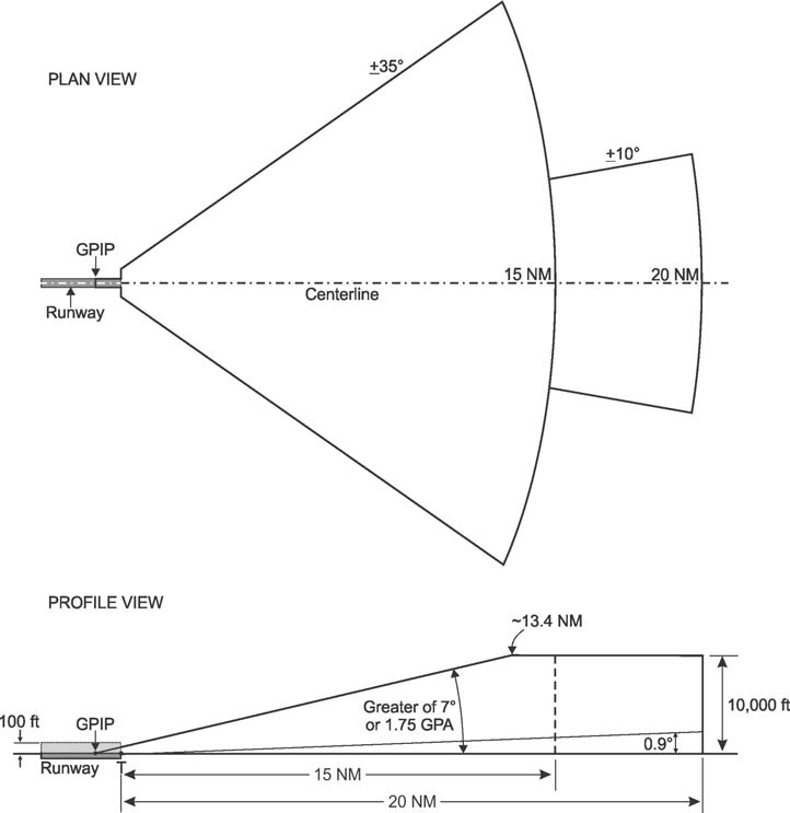
-
A GBAS ground installation at an airport can provide localized, differential augmentation to the Global Positioning System (GPS) signal-in-space enabling an aircraft's GLS precision approach capability. Through the GBAS service and the aircraft's GLS installation a pilot may complete an instrument approach offering three-dimensional angular, lateral, and vertical guidance for exact alignment and descent to a runway. The operational benefits of a GLS approach are similar to the benefits of an ILS or LPV approach operation.
-
Precision Approach Systems other than ILS and GLS
-
General
Approval and use of precision approach systems other than ILS and GLS require the issuance of special instrument approach procedures. -
Special Instrument Approach Procedure
- Special instrument approach procedures must be issued to the aircraft operator if pilot training, aircraft equipment, and/or aircraft performance is different than published procedures. Special instrument approach procedures are not distributed for general public use. These procedures are issued to an aircraft operator when the conditions for operations approval are satisfied.
-
General aviation operators requesting approval for special procedures should contact the local Flight Standards District Office to obtain a letter of authorization. Air carrier operators requesting approval for use of special procedures should contact their Certificate Holding District Office for authorization through their Operations Specification.
REFERENCE-
AIM, Para 5-4-7, Instrument Approach Procedures, Subpara i.
-
General